Download presentation
Presentation is loading. Please wait.

1
computer networks Communication Requirements for a network
Topologie of computer networks ISO / OSI reference modell Variety of cables fiber optic cable Twisted Pair coaxial cable WLAN Wi-Fi transmission methods Ethernet Token Ring TCP / IP

2
Attributes of Communication
Participants Human to human Application system to application system Human to application system Direction Unidirectional versus bidirectional Dialogue

3
Attributes of Communication
Distribution Number of recipient Contextual recipient Nature Oral, written, image Standard of communication Distance (size / performance = time) Trigger Push or pull
 Trigger. Push or pull.")
4
Requirements of a network
The speed must saisfy the partners. The management of the components and the end devices as terminals, printers, ... must be simple The operating expenses must be economically justifiable.

5
Basic elements of a network
Computers and nodes which are connected Infrastructure components which connect the computers wiring

6
Client / Server Netz Offer resources and services sends orders to a
to the public. One server can get orders from several Clients sends orders to a service provider. A Client can address several servers Netz The cooperation is initiated by the client, who sends orders to a service provider. The service provider states its readiness to be available for certain services. During the processing he client can address several servers and a server can server several The server offers only well defined services. It accepts orders only when it is idle. If a server is accepting an order, it must verify the following: Is the client really that one it claims to be? If yes, is the client authorized to perform the intended operation with the desired data?

7
Categories of networks

8
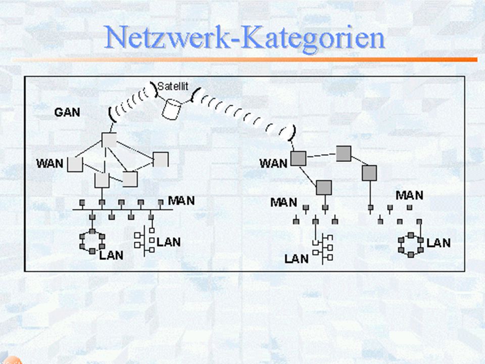
Categories of networks
Private networks Public networks Local Area Network LAN Metropolian Area Network MAN Wide Area Network WAN Dimension Campus ca. 500 m Region ca100 km unlimited Speed Mbits/s 1 Gbits/s Mbits/s bis 64 Kbits/s bis 2,5 Gbits/s Application Data Images Data MM Data Speach Data Images Data, Video Speach Technologie Ethernet Token Ring FDDI DSL Ethernet DSL analog ISDN DSL

10
transmission methods Direct connection between Client and Server
Store and Forward network Broadcast network Direct connection between transmitter and receiver: Both must adapt themselves to a common transmission rate. The data can be transmitted as a continous data stream or as data packets. Store and Forward network: The data are seperated into independent units and are transferred as seperate packets. The packets are transmitted to the next node and stored at this node. Each node calculate the optimal connection to the destination and forwards ist packets. Thus it is possible, that the packets will arrive in a randomly order at the receiver. The receiver has to put the packets in the correct order. Broadcast: The transmitter transmitts the data in a common medium, to which several receivers are connected. The desired receiver filters the packets which are addressed to him.

11
Telephone: direct connection

12
Internet: Store and Forward
Local Network Internet Data packet Local network Jeder Netzwerkrechner (Router) kennt die Verbindungen in seine Umgebung. Er weiß ob und wie gut die Verbindung funktioniert. Ein Router analysiert die eingehenden Datenpakete, erkennt das Ziel eines Datenpaketes und weiß, an welchen Nachbarn er das Paket weitergeben muß. Am Ziel wird die Nachricht aus den einzelnen Paketen in der richtigen Reihenfolge zusammengesetzt und an den Empfänger übergeben. Fehlende oder fehlerhafte Pakete können nachgefordert werden. Im Jahr 1974 wurde ein Protokoll (=die Verarbeitungsvorschrift) zur Übertragung von Datenpaketen definiert, das TCP/IP (Transmission Control Protocol / Internet Protocol). Im Jahre 1984 wurde TCP/IP zusammen mit dem Betriebssystem UNIX kostenlos von SUN vertrieben. Damit setzte sich TCP/IP als Standard für die Datenübertragung in Rechnernetzen durch. Mehrere bestehende Rechnernetze (z.B. APAR-NET,BITNET, CSNET, Earn= European Academic Research Net) konnten zusammengeknüpft werden, das Internet war am Entstehen. Das Prinzip der Übertragung besteht darun, eingehende Pakete aufzusammeln und an den nächsten Empfänger weiterzureichen. Jeder Router hat also die Möglichkeit, die Daten zu lesen und Kopien davon anzufertigen. Prinzipiell können die Daten auch verfälscht werden.
 kennt die Verbindungen in seine Umgebung. Er weiß ob und wie gut die Verbindung funktioniert. Ein Router analysiert die eingehenden Datenpakete, erkennt das Ziel eines Datenpaketes und weiß, an welchen Nachbarn er das Paket weitergeben muß. Am Ziel wird die Nachricht aus den einzelnen Paketen in der richtigen Reihenfolge zusammengesetzt und an den Empfänger übergeben. Fehlende oder fehlerhafte Pakete können nachgefordert werden. Im Jahr 1974 wurde ein Protokoll (=die Verarbeitungsvorschrift) zur Übertragung von Datenpaketen definiert, das TCP/IP (Transmission Control Protocol / Internet Protocol). Im Jahre 1984 wurde TCP/IP zusammen mit dem Betriebssystem UNIX kostenlos von SUN vertrieben. Damit setzte sich TCP/IP als Standard für die Datenübertragung in Rechnernetzen durch. Mehrere bestehende Rechnernetze (z.B. APAR-NET,BITNET, CSNET, Earn= European Academic Research Net) konnten zusammengeknüpft werden, das Internet war am Entstehen. Das Prinzip der Übertragung besteht darun, eingehende Pakete aufzusammeln und an den nächsten Empfänger weiterzureichen. Jeder Router hat also die Möglichkeit, die Daten zu lesen und Kopien davon anzufertigen. Prinzipiell können die Daten auch verfälscht werden.")
13
Radio: Broadcast

14
Topology of the computer connections
Star Ring Bus

15
Topologie Star Ring Bus - Long cables
+ When a cable breaks, only one component fails - Long cables Ring + shortest cables, best transmission characteristic When a cable breaks or one component fails, the whole transmission fails Bus + most simple cabling - Problems with simultaneous transmissions Star: With this design, each computer has ist own connection to a central unit. The amount of cable is much more than with the other designs. But when one connectin fails, only one end device is affected. However, if the central unit fails, this failure can not be ompensated. Ring: Each unit has exasctlx one right and one left neighbor, Messages are forwarded in a well defined way. If only one unit fails, the ring is disconnected and no message can be propagated. The advantages of this design is simple expansion, low amount of cable and optimal transmission characteristics. Bus: The involved units are connected by a central wire. The ends of this wire must be terminated in order to avoid interferences. If the central cable is broken, remain two seperate networks.

16
Verkabelung

17
Heinrich - Braun - Krankenhaus Zwickau
18
Zentralkrankenhaus central - hospital Klinikum Hannover Oststadt
19
Pavillon – Krankenhaus Pavilion - hospital

20
Krankenhausverbund network of hospitals

21
Campus

22
Primärverkabelung primary cables backbone

23
ISO / OSI Referenzmodell
International Standards Organization Open System Interconnect Reference Model consists of 7 layers, which realise the different tasks of the data communication. The ISO/OSI Referenzmodell (International Organisation for Standardisation / Open System Interconnection) is a theoretical model which describes the data exchange between two computers. The tasks are realisied by different tasks, which are arranged in layers. Each layer gets ist order from the layer above and delegates a subtask to the layer directly below.
 is a theoretical model which describes the data exchange between two computers. The tasks are realisied by different tasks, which are arranged in layers. Each layer gets ist order from the layer above and delegates a subtask to the layer directly below.")
24
ISO / OSI layers http://www.interfacebus.com/Design_OSI_Stack.html
Layer 1. Physical: Defines the physical [hardware] implementation and the electrical [signal level] implementation of the bus; network cabling, connector type, pin-out, physical data rates, maximum transmission distances, and data transmission encoding. At this layer information is placed on the physical network medium. RS-232, and RS422 are examples of a physical layer specification. Protocol Data Unit [PDU] is called a Bit at this layer. Other physical layer specifications are listed on the Electronic Bus page. Schicht1: Bitübertragungsschicht. Definition der Übertragungskabel, Definition der elektrischen Darstellung der Bits: Takt, Pulsdauer, Modulation, Codierung. Layer 2. Data Link: Frame format, Transmitting frames over the net [additional bit/byte stuffing, start / stop flags, checksum, and CRC]. CAN bus, ATM, StarLAN, LocalTalk and HDLC are layer 2 protocols. Different network and protocol characteristics are defined by different data link layer specifications. The Data Link layer is subdivided into the Media Access Control (MAC) which controls access and encodes data into a valid signaling format [for the physical layer], and the Logical Link Control (LLC), which provides the link to the network [for the Network layer] Protocol Data Unit [PDU] is called a Frame at this layer. Schicht 2: Leitungsschicht. Erkennen von Übertagungsfehlern, Flußregelung (Sender nicht schneller als der Empfänger). Definition des Leitungszugriffs (Bus, Stern, Ring) Layer 3. Network: Provides address assignment, and Packet's forwarding methods. Protocol Data Unit [PDU] is called a Packet at this layer. Schicht 3: Netzschicht. Auswahl der Übertragungsweges (Routing), Vermittlung, Verkehrssteuerung (bei Überlastung), Multiplexing, Flußregelung bei Multiplexing, Fehlerbehandlung (Reihenfolge der Pakete sicherstellen). Layer 4. Transport: Provides transfer correctness, data recovery, and flow control. TCP is a layer 4 protocol. Protocol Data Unit [PDU] is called a Segment at this layer. Schicht 4: Transportschicht. Verbindung zwischen den Prozessen unterstützen (end to end), Dienstgüte überwachen, Segmentierung von Transportdaten, geregelter Abbau der Verbindung, Datenflußkontrolle Layer 5. Session: Establishing a communication session, Security, Authentication. NetBIOS is a layer 5 protocol. Protocol Data Unit [PDU] is called Data at this layer. Schicht 5: Kommunikationssteuerung. Synchronisation zwischen den Prozessen. Layer 6. Presentation: Determines how computers represent data [ASCII, GIF..]. Protocol Data Unit [PDU] is called Data at this layer. Schicht 6: Darstellung. Gemeinsame Syntax beider Übertragungspartner festlegen (RISC Prozessoren habe das größte Bit links, Intelprozessoren haben es rechts), Verschlüsselung Layer 7. Application: Generates or interprets data, may also provide encryption or decryption. Applications using the network learn how to send a request, how to specify a filename over the net, how to respond to a request. Protocol Data Unit [PDU] is called Data at this layer Schicht 7: Anwendung. Standardisierung der Dienste. Z.B.: FTP, HTTP, EDIFACT The strict hierarchisation of the tasks and the restriction that the programs of one layer are only allowed to communicate with the programs directly above and below, refused broad practical application to this model. Existing transmission protocols use this reference modell to describe their scope of services.
 which controls access and encodes data into a valid signaling format [for the physical layer], and the Logical Link Control (LLC), which provides the link to the network [for the Network layer] Protocol Data Unit [PDU] is called a Frame at this layer. Schicht 2: Leitungsschicht. Erkennen von Übertagungsfehlern, Flußregelung (Sender nicht schneller als der Empfänger). Definition des Leitungszugriffs (Bus, Stern, Ring) Layer 3. Network: Provides address assignment, and Packet s forwarding methods. Protocol Data Unit [PDU] is called a Packet at this layer. Schicht 3: Netzschicht. Auswahl der Übertragungsweges (Routing), Vermittlung, Verkehrssteuerung (bei Überlastung), Multiplexing, Flußregelung bei Multiplexing, Fehlerbehandlung (Reihenfolge der Pakete sicherstellen). Layer 4. Transport: Provides transfer correctness, data recovery, and flow control. TCP is a layer 4 protocol. Protocol Data Unit [PDU] is called a Segment at this layer. Schicht 4: Transportschicht. Verbindung zwischen den Prozessen unterstützen (end to end), Dienstgüte überwachen, Segmentierung von Transportdaten, geregelter Abbau der Verbindung, Datenflußkontrolle. Layer 5. Session: Establishing a communication session, Security, Authentication. NetBIOS is a layer 5 protocol. Protocol Data Unit [PDU] is called Data at this layer. Schicht 5: Kommunikationssteuerung. Synchronisation zwischen den Prozessen. Layer 6. Presentation: Determines how computers represent data [ASCII, GIF..]. Protocol Data Unit [PDU] is called Data at this layer. Schicht 6: Darstellung. Gemeinsame Syntax beider Übertragungspartner festlegen (RISC Prozessoren habe das größte Bit links, Intelprozessoren haben es rechts), Verschlüsselung. Layer 7. Application: Generates or interprets data, may also provide encryption or decryption. Applications using the network learn how to send a request, how to specify a filename over the net, how to respond to a request. Protocol Data Unit [PDU] is called Data at this layer. Schicht 7: Anwendung. Standardisierung der Dienste. Z.B.: FTP, HTTP, EDIFACT. The strict hierarchisation of the tasks and the restriction that the programs of one layer are only allowed to communicate with the programs directly above and below, refused broad practical application to this model. Existing transmission protocols use this reference modell to describe their scope of services.")
25
ISO / OSI layers Anwendung - Application Darstellung - Presentation
Sicherung - Data Link Physikalisch - Physical Netzwerk - Network Transport - Transport Anwendung - Application Darstellung - Presentation Sitzung - Session

26
Cabling Primary cabling: between buildings
Fiber optics Coaxial cable Radio relay system Secundary cabling: main cable in building Tertiary cabling: within a floor (often a star) WLAN (radio network)
 WLAN (radio network)")
27
Fiber optics Sender or Source Analog / Digital Converter Driver unit
LED Fiber Photo transistor Digital / Analog Converter Driver unit Receiver transfer rate: 200 Mbit/s to 1 Gbit/s

28
Twisted Pair transfer rate : 1 Mbit/s bis 300 Mbit/s
Abschirmung: shielding Kupfergeflecht: copper netting Aluminumfolie: aluminium foil Kunstoffmantel: plastic coat The twisted pair cable consists of two wires which are turned around each other. Contrary to asymmetrical cables, as coaxial cables they do not need a grounding. The advantage of this kind of cable is the little sensitiveness against electromagnetic interferences.

29
Coaxial cable http://en.wikipedia.org/wiki/Coaxial_cable
transfer rate : 1 Mbit/s bis 600 Mbit/s

30
transmission capacity

31
WLAN Wireless local area network Wi-Fi Wi-Fi Alliance WECA (Wireless Ethernet Compatibility Alliance) Accesspoint

32
Range of WLAN Up to 100 m outdoor, Limited by Walls
Ferroconcrete, Metal Water Humide walls Road-leaved trees Interferences with other equipment

33
Security of WLAN Without any precaution everybody in the range of communication can use the network an can put a trace on teh communication. Precaution: MAC-Address: only dedicated equipment can use the network WEP Wired Equivalent Privacy: 128 Bit Key, no more safe WPA2 Wi-Fi Protected Access: 256 Bit Key

34
ISO / OSI layers Anwendung - Application Darstellung - Presentation
Sicherung - Data Link Physikalisch - Physical Netzwerk - Network Transport - Transport Anwendung - Application Darstellung - Presentation Sitzung - Session

35
Ethernet Bus with 10Mbit/s and 100Mbit/s Segments up to 500 m
Connection of segments with repeaters Bridges Router (Weiterleiter) Hub (Zentrum, Nabe)
 Hub (Zentrum, Nabe)")
36
Ethernet CSMA/CD Carrier Sense Multiple Access with Collision Detect
The transmitter sends whenever it gets the order from the calling programm. Accidently it may happen that two transmitter will send at the same time and will intetfere with eachother. To avoid such collisiens, each transmitter listens to the receiving date. If the transmitter receives something different from ist own data, it suspects a collision and interrupts the transmission as the other sending device is doing. After a random time intervall the transmitter starts again. When many active devices are are connected to one segment, it happens more often that two devices will send at the same time. Oth will wait for an randonm time and will try again and again will hav the cahnce to interfere with some other device and very soon the segment will break down. CSMA/CD Carrier Sense Multiple Access with Collision Detect Carrier Sense: Prüfen des Übertragungsmediums, ob zur Zeit gesendet wird. Wenn das Medium frei ist, darf gesendet werden. Multiple Access: Es darf von mehreren gleichzeitig gesendet werden. Collision Detect: Der Sender überprüft die gesendete Information mit der empfangenen, wenn die Information verfälscht ist, besteht der Verdacht, daß ein weiterer Sender gleichzeitig angefangen hat zu senden. Beide Sender unterbrechen ihre Aktionen und starten nach einer durch einen Zufallsgenerator erzeugten Zeitspanne erneut. Dieses Verfahren führt dazu, daß bei einer hohen Netzauslastung die Wahrscheinlichkeit der Kollision zunimmt und das Netz durch weitere Versuche, die gleichen Daten erneut zu senden, stärker überlastet wird. Bei einer Auslastung von 40% der maximalen Übertragungsrate steigt die Anzahl der Kollisionen überdurchschnittlich an und läßt den Netzwerkverkehr zum Erliegen kommen.

37
Token Ring Before starting to transmit, the sender has to wait for a permission (Token). All devices forward foreign packets. When the data arrive at the receiver it will remove the data and forwards the empty token.

38
Token Ring

39
Connection elements Repeater
A Repeater works at the physical layer. It repeats and apmlifies signals into a second segment.

40
Connection elements Hub
A hub works at the physical layer. It is the center of a star topology which builds a logical bus.Like a bus, all connected devices get all transmitted information. Hubs can be cascaded.

41
Connection elements Bridge
A bridge works at the second level, the data link level. A bridge connects two segments. The bridge knows the addresses of both segments and forwards only those messages which are addressed to a device on the other side.

42
Connection elements Router
A router is a device with connections to at least two networks. It works at the third level, the network layer. A router can connect networks with different technologies.

43
ISO / OSI Schichten Anwendung - Application Darstellung - Presentation
Sicherung - Data Link Physikalisch - Physical Netzwerk - Network Transport - Transport Anwendung - Application Darstellung - Presentation Sitzung - Session

44
TCP/IP Objectivs Independent of the network technologie and the server technologie All-purpose transmission End – to – end connection Standardised protocols These objectivs were formulated 1974 by V. Cerf and R. Kahn. The first two objectivs, independence and universality were unusual at the time. At that time normally computer systems consists of devices of only one company. The communication protocolls were normally secret and connection between computers of different companies were difficult to impossible. The university of california Berkley has developed the TCP/IP protocols for their UNIX system and made them in 1983 available as public domaine software. That contributed substantially to the success of TCP/PI.

45
ISO / OSI layers Anwendung - Application Darstellung - Presentation
Sicherung - Data Link Physikalisch - Physical Netzwerk - Network Transport - Transport Anwendung - Application Darstellung - Presentation Sitzung - Session

46
TCP/IP IP-Protokoll Selection of the route
Converting the global address to a local address Buffer of messages Assemble fragmented messages Avoiding infinite loops On the basis a cost table IP can determine the most favorable next node for the transmission of a message Normally exist several possibilities. It is possible that the local area network is larger than the network as it is senn from outside and the local adresses are different from the adresses senn from outside Messages are stored and forwarded. The message is divided into fragments which can take different routes through the network. They can reach the destination in an random order. Each involved node can determine the route to the destination. So it is possible that a message can fall into an infinite loop. A lifetime parameter in the header is decreased at each node. When the parameter gets the value 0 the message will be destroysed.

47
ISO / OSI Schichten Anwendung - Application Darstellung - Presentation
Sicherung - Data Link Physikalisch - Physical Netzwerk - Network Transport - Transport Anwendung - Application Darstellung - Presentation Sitzung - Session

48
TCP/IP TCP-Protokoll Main objective: safe transportation of data through the network full-duplex virtual connection Transmission as a stream Sequenznumbers sliding-Window-function Controlled connection termination

49
ISO / OSI Schichten Anwendung - Application Darstellung - Presentation
Sicherung - Data Link Physikalisch - Physical Netzwerk - Network Transport - Transport Anwendung - Application Darstellung - Presentation Sitzung - Session

50
Anwendungen HTTP : transmission of HTML FTP : Filetransfer
electronical mail telnet : Terminalemulation NFS : Networkdata

51
Formats for data exchange
XML EDIFACT HL 7 (Helth Level 7) ADT (Abrechnungsdatentypen) BDT (Behandlungsdatentypen)
 ADT (Abrechnungsdatentypen) BDT (Behandlungsdatentypen)")
Similar presentations


 High-Speed LANs. 2 Introduction Fast Ethernet and Gigabit Ethernet Fast Ethernet and Gigabit Ethernet Fibre Channel Fibre Channel High-speed.>")


>")


