Download presentation
Presentation is loading. Please wait.

1
ESP (Electrostatic precipitator)
")
2
Operating Principles Step 1 is the electrical charging and migration of particles toward a vertical collection surface. Step 2 involves the gravity settling (or draining in the case of liquids) of the collected material from the vertical collection surfaces. Step 3 is the removal of the accumulated solids or liquids from the hopper or sump below the electrically energized zone.
 of the collected material from the vertical collection surfaces. Step 3 is the removal of the accumulated solids or liquids from the hopper or sump below the electrically energized zone.")
3
Particle Charging

9
Types of Electrostatic Precipitators
The structural design and operation of the discharge electrodes (rigid-frame, wires or plate) and collection electrodes (tubular or plate) The method of charging (single-stage or two-stage) The temperature of operation (cold-side or hot-side) The method of particle removal from collection surfaces (wet or dry)
 and collection electrodes (tubular or plate) The method of charging (single-stage or two-stage) The temperature of operation (cold-side or hot-side) The method of particle removal from collection surfaces (wet or dry)")
11
Tubular precipitators consist of cylindrical collection electrodes (tubes) with discharge electrodes (wires) located in the center of the cylinder. Dirty gas flows into the tubes, where the particles are charged. The charged particles are then collected on the inside walls of the tubes. Collected dust and/or liquid is removed by washing the tubes with water sprays located directly above the tubes. The tubes may be formed as a circular, square, or hexagonal honeycomb with gas flowing upward or downward. A tubular ESP is tightly sealed to minimize leaks of collected material. Tube diameters typically vary from 0.15 to 0.31 m (0.5 to 1 ft), with lengths usually varying from 1.85 to 4.0m (6 to 15 ft). Tubular precipitators are generally used for collecting mists or fogs, and are most commonly used when collecting particles that are wet or sticky. Tubular ESPs have been used to control particulate emissions from sulfuric acid plants, coke oven byproduct gas cleaning (tar removal), and iron and steel sinter plants.
, and iron and steel sinter plants.")
12
Plate electrostatic precipitators primarily collect dry particles and are used more often
than tubular precipitators. Plate ESPs can have wire, rigid-frame, or occasionally, plate discharge electrodes. Figure 1-11 shows a plate ESP with wire discharge electrodes. Dirty gas flows into a chamber consisting of a series of discharge electrodes that are equally spaced along the center line between adjacent collection plates. Charged particles are collected on the plates as dust, which is periodically removed by rapping or water sprays. Discharge wire electrodes are approximately 0.13 to 0.38 cm (0.05 to 0.15 in.) in diameter. Collection plates are usually between 6 and 12 m (20 and 40 ft) high. For ESPs with wire discharge electrodes, the plates are usually spaced from 15 to 30 cm (6 to 12 in.) apart. For ESPs with rigid-frame or plate discharge electrodes, plates are typically spaced 30 to 38 cm(12 to 15 in.) apart and 8 to 12 m (30 to 40 ft) in height. Plate ESPs are typically used for collecting fly ash from industrial and utility boilers as well as in many other industries including cement kilns, glass plants and pulp and paper mills.
 in diameter. Collection plates are usually between 6 and 12 m (20. and 40 ft) high. For ESPs with wire discharge electrodes, the plates are usually spaced. from 15 to 30 cm (6 to 12 in.) apart. For ESPs with rigid-frame or plate discharge electrodes, plates are typically spaced 30 to 38 cm(12 to 15 in.) apart and 8 to 12 m (30 to. 40 ft) in height. Plate ESPs are typically used for collecting fly ash from industrial and utility boilers. as well as in many other industries including cement kilns, glass plants and pulp and. paper mills.")
13
A single-stage precipitator uses high voltage to charge the
particles, which are then collected within the same chamber on collection surfaces of opposite charge. In a two-stage precipitator, particles are charged by low voltage in one chamber, and then collected by oppositely charged surfaces in a second chamber.

14
Single Stage Most ESPs that reduce particulate emissions from boilers and other industrial processes are single-stage ESPs (these units will be emphasized in this course). Singlestage ESPs use very high voltage (50 to 70 kV) to charge particles. After being charged, particles move in a direction perpendicular to the gas flow through the ESP, and migrate to an oppositely charged collection surface, usually a plate or tube. Particle charging and collection occurs in the same stage, or field; thus, the precipitators are called single-stage ESPs. The term field is used interchangeably with the term stage and is described in more detail later in this course. Figure 1-10 shows a singlestage tubular precipitator. A single-stage plate precipitator is shown in Figure 1-11.
. Singlestage. ESPs use very high voltage (50 to 70 kV) to charge particles. After being. charged, particles move in a direction perpendicular to the gas flow through the ESP, and migrate to an oppositely charged collection surface, usually a plate or tube. Particle. charging and collection occurs in the same stage, or field; thus, the precipitators. are called single-stage ESPs. The term field is used interchangeably with the term. stage and is described in more detail later in this course. Figure 1-10 shows a singlestage. tubular precipitator. A single-stage plate precipitator is shown in Figure")
15
Representation of gas flow in a two-stage precipitator

16
The two-stage ESP has separate particle charging and collection
stages (Figure 1-12). The ionizing stage consists of a series of small, positively charged wires equally spaced 2.5 to 5.1 cm (1 to 2 in.) from parallel grounded tubes or rods. A corona discharge between each wire and a corresponding tube charges the particles suspended in the air flow as they pass through the ionizer. The direct-current potential applied to the wires is approximately 12 to 13 kV. The second stage consists of parallel metal plates less than 2.5 cm (1 in.) apart. The particles receive a positive charge in the ionizer stage and are collected at the negative plates in the second stage. Collected smoke or liquids drain by gravity to a pan located below the plates, or are sprayed with water mists or solvents that remove the particles and cause them to fall into the bottom pan. Two-stage precipitators were originally designed for air purification in conjunction with air conditioning systems. (They are also referred to as electronic air filters). Twostage ESPs are used primarily for the control of finely divided liquid particles. Controlling solid or sticky materials is usually difficult, and the collector becomes ineffective for dust loadings greater than 7.35 x 10⁻³g/m3 (0.4 gr/dscf). Therefore, two-stage precipitators have limited use for particulate-emission control. They are used almost exclusively to collect liquid aerosols discharged from sources such as meat smokehouses, pipe-coating machines, asphalt paper saturators, high speed grinding machines, welding machines, and metal-coating operations.
. The ionizing stage consists of a series of small, positively. charged wires equally spaced 2.5 to 5.1 cm (1 to 2 in.) from parallel grounded tubes or. rods. A corona discharge between each wire and a corresponding tube charges the particles. suspended in the air flow as they pass through the ionizer. The direct-current. potential applied to the wires is approximately 12 to 13 kV. The second stage consists of parallel metal plates less than 2.5 cm (1 in.) apart. The. particles receive a positive charge in the ionizer stage and are collected at the negative. plates in the second stage. Collected smoke or liquids drain by gravity to a pan located. below the plates, or are sprayed with water mists or solvents that remove the particles. and cause them to fall into the bottom pan. Two-stage precipitators were originally designed for air purification in conjunction. with air conditioning systems. (They are also referred to as electronic air filters). Twostage. ESPs are used primarily for the control of finely divided liquid particles. Controlling. solid or sticky materials is usually difficult, and the collector becomes ineffective. for dust loadings greater than 7.35 x 10⁻³g/m3 (0.4 gr/dscf). Therefore, two-stage. precipitators have limited use for particulate-emission control. They are used almost. exclusively to collect liquid aerosols discharged from sources such as meat smokehouses, pipe-coating machines, asphalt paper saturators, high speed grinding. machines, welding machines, and metal-coating operations.")
17
Electrostatic precipitators are also grouped according to the temperature of the flue gas that enters the ESP: cold-side ESPs are used for flue gas having temperatures of approximately 204°C (400°F) or less; hot-side ESPs are used for flue gas having temperatures greater than 300°C (572°F). cold side and hot side also refer to the placement of the ESP in relation to the combustion air preheater. A cold-side ESP is located behind the air preheater, whereas a hot-side ESP is located in front of the air preheater. The air preheater is a tube section that preheats the combustion air used for burning fuel in a boiler.
 or less; hot-side ESPs are used for flue gas having temperatures. greater than 300°C (572°F). cold side and hot side also refer to the placement of the ESP in relation to the combustion air preheater. A cold-side ESP is located behind the air preheater, whereas a hot-side ESP is located in front of the air preheater. The air preheater is a tube section that preheats the combustion air used for burning fuel in a boiler.")
18
Cold-side ESPs have been used for over 50 years with industrial and
utility boilers, where the flue gas temperature is relatively low (less than 204°C or 400°F). Cold-side ESPs generally use plates to collect charged particles. Because these ESPs are operated at lower temperatures than hot-side ESPs, the volume of flue gas that is handled is less. Therefore, the overall size of the unit is smaller, making it less costly. Cold-side ESPs can be used to remove fly ash from boilers that burn high sulfur coal. As explained in later lessons, cold-side ESPs can effectively remove fly ash from boilers burning low-sulfur coal with the addition of conditioning agents.
. Cold-side ESPs generally use plates to collect charged particles. Because these ESPs are operated at lower temperatures than hot-side ESPs, the volume of flue gas that is handled is less. Therefore, the overall size of the unit is smaller, making it less costly. Cold-side ESPs can be used to remove fly ash from boilers that burn high sulfur coal. As explained in later lessons, cold-side ESPs can effectively remove fly ash from boilers burning low-sulfur coal with the addition of conditioning agents.")
19
A hot-side precipitator is located before the combustion air preheater in a boiler. The flue gas temperature for hot-side precipitators is in the range of 320 to 420°C (608 to 790°F). The use of hot-side precipitators help reduce corrosion and hopper plugging. However, these units (mainly used on coal-fired boilers) have some disadvantages. Because the temperature of the flue gas is higher, the gas volume treated in the ESP is larger. Consequently, the overall size of the precipitator is larger making it more costly. Other major disadvantages include structural and mechanical problems that occur in the precipitator shell and support structure as a result of differences in thermal expansion.
. The use of hot-side precipitators help reduce corrosion and hopper plugging. However, these units (mainly used on coal-fired boilers) have some disadvantages. Because the temperature of the flue gas is higher, the gas volume treated in the ESP is larger. Consequently, the overall size of the precipitator is larger making it more costly. Other major disadvantages include structural and mechanical problems that occur in the precipitator shell and support structure as a result of differences in thermal expansion..")
20
For years, cold-side ESPs were used successfully on boilers burning high-sulfur coal. However, during the 1970s when utilities switched to burning low-sulfur coal, coldside ESPs were no longer effective at collecting the fly ash. Fly ash produced from low sulfur coal-fired boilers has high making it difficult to collect. As you will learn later, high temperatures can lower resistivity. Consequently, hot-side ESPs became very popular during the 1970s for removing ash from coal-fired boilers burning low sulfur coal. However, many of these units did not operate reliably, and therefore, since the 1980s, operators have generally decided to use cold-side ESPs along with conditioning agents when burning low sulfur coal. Hot-side ESPs are also used in industrial applications such as cement kilns and steel refining furnaces. In these cases, combustion air preheaters are generally not used and hot side just refers to the high flue gas temperature prior to entering the ESP.

21
Wet ESPs Any of the previously described ESPs can be operated with a wet spray to remove collected particles. Wet ESPs are used for industrial applications where the potential for explosion is high (such as collecting dust from a closed-hood Basic Oxygen Furnace in the steel industry), or when dust is very sticky, corrosive, or has very high resistivity. The water flow may be applied continuously or intermittently to wash the collected particles from the collection electrodes into a sump (a basin used to collect liquid). The advantage of using a wet ESP is that it does not have problems with rapping reentrainment or with back corona.
, or when dust is very sticky, corrosive, or has very high resistivity. The water flow may be applied continuously or intermittently to wash the collected particles from the collection electrodes into a sump (a basin used to collect liquid). The advantage of using a wet ESP is that it does not have problems with rapping reentrainment or with back corona.")
22
Dry ESPs Most electrostatic precipitators are operated dry and use rappers to remove the collected particulate matter. The term dry is used because particles are charged and collected in a dry state and are removed by rapping as opposed to water washing which is used with wet ESPs. The major portion of this course covers dry ESPs that are used for collecting dust from many industries including steel furnaces, cement kilns and fossil-fuel-fired boilers.

23
Precipitator Components
Discharge electrodes Collection electrodes High voltage electrical systems Rappers Hoppers Shell

24
Guide frames and shrouds for
discharge wires Typical wire dischare electrodes

25
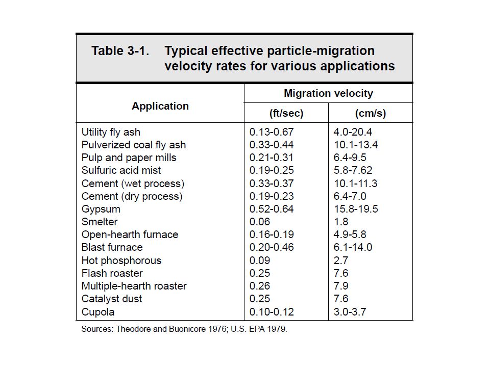
Particle-migration velocity, or drift Velocity
The migration-velocity parameter represents the collectability of the particle within the confines of a specific ESP. The migration velocity is expressed as: Where: dp = diameter of the particle, μm Eo = strength of field in which particles are charged (represented by peak voltage), V/m (V/ft) Ep = strength of field in which particles are collected (normally the field close to the collecting plates), V/m (V/ft) μ = gas viscosity, Pa • s (cp) π = 3.14
, V/m (V/ft) Ep = strength of field in which particles are collected (normally the field close to the collecting plates), V/m (V/ft) μ = gas viscosity, Pa • s (cp) π =")
26
Particle-migration velocity can also be determined by:
Where: q = particle charge(s) Ep = strength of field in which particles are collected, V/m (V/ft) μ = gas viscosity, Pa • s (cp) r = radius of the particle, μm π = 3.14 The particle-migration velocity can be calculated using either Equations 3-1 or 3-2, depending on the information available on the particle size and electric field strength. However, most ESPs are designed using a particle-migration velocity based on field experience rather than theory.
 Ep = strength of field in which particles are collected, V/m (V/ft) μ = gas viscosity, Pa • s (cp) r = radius of the particle, μm. π = The particle-migration velocity can be calculated using either Equations 3-1 or 3-2, depending on the information available on the particle size and electric field strength. However, most ESPs are designed using a particle-migration velocity based on field experience rather than theory.")
28
Deutsch-Anderson Equation
Probably the best way to gain insight into the process of electrostatic precipitation is to study the relationship known as the Deutsch-Anderson equation. This equation is used to determine the collection efficiency of the precipitator under ideal conditions. The simplest form of the equation is given below. Where: η = collection efficiency of the precipitator e = base of natural logarithm = 2.718 w = migration velocity, cm/s (ft/sec) A = the effective collecting plate area of the precipitator, m2 (ft2) Q = gas flow through the precipitator, m3/s (ft3/sec)
 A = the effective collecting plate area of the precipitator, m2 (ft2) Q = gas flow through the precipitator, m3/s (ft3/sec)")
29
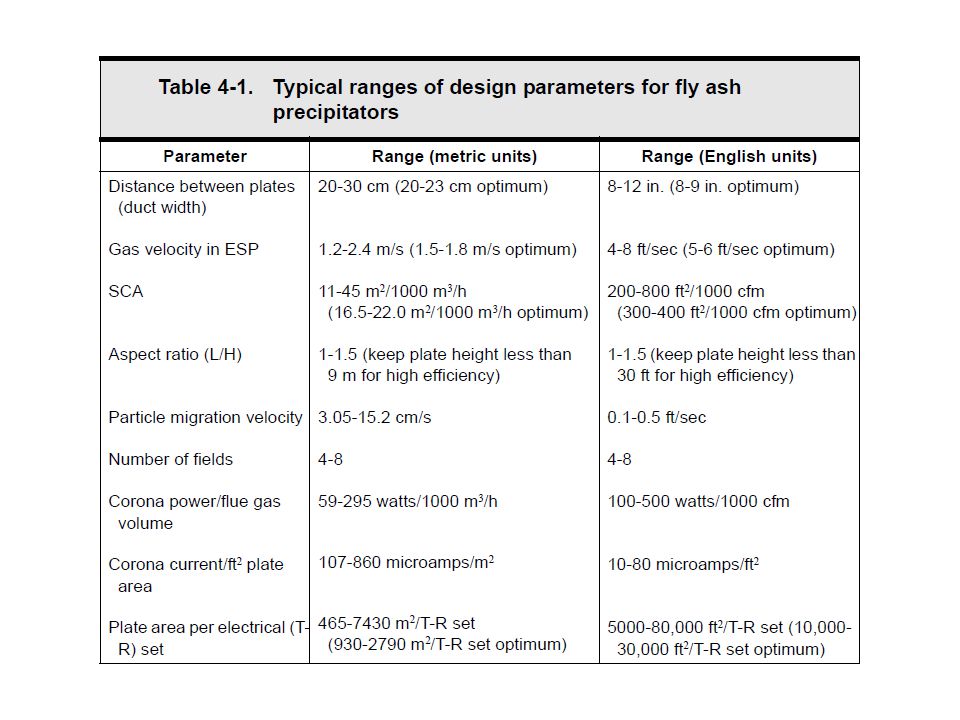
ESP Design • Specific collection area • Collection plate area
• Collection height and length • Gas velocity • Number of fields in series • Number of discharge electrodes • Type of discharge electrodes • Discharge electrode-to-collection plate spacing

30
Particulate Matter and Gas Stream Data
• Resistivity • Particle size mass median diameter • Particle size distribution standard deviation • Gas flow rate distribution standard deviation • Actual gas flow rate • Gas stream temperature • Gas stream pressure • Gas stream composition

31
High Resistivity If the voltage drop across the dust layer becomes too high, several adverse effects can occur. First, the high voltage drop reduces the voltage difference between the discharge electrode and collection electrode, and thereby reduces the electrostatic field strength used to drive the gas ion - charged particles over to the collected dust layer. As the dust layer builds up, and the electrical charges accumulate on the surface of the dust layer, the voltage difference between the discharge and collection electrodes decreases. The migration velocities of small particles are especially affected by the reduced electric field strength. Another problem that occurs with high resistivity dust layers is called back corona. This occurs when the potential drop across the dust layer is so great that corona discharges begin to appear in the gas that is trapped within the dust layer. The dust layer breaks down electrically, producing small holes or craters from which back corona discharges occur. Positive gas ions are generated within the dust layer and are accelerated toward the "negatively charged" discharge electrode. The positive ions reduce some of the negative charges on the dust layer and neutralize some of the negative ions on the "charged particles" heading toward the collection electrode. Disruptions of the normal corona process greatly reduce the ESP's collection efficiency, which in severe cases, may fall below 50% (White 1974). The third, and generally most common problem with high resistivity dust is increased electrical sparking. When the sparking rate exceeds the "set spark rate limit," the automatic controllers limit the operating voltage of the field. This causes reduced particle charging and reduced migration velocities toward the collection electrode.
. The third, and generally most common problem with high resistivity dust is increased electrical sparking. When the sparking rate exceeds the set spark rate limit, the automatic controllers limit the operating voltage of the field. This causes reduced particle charging and reduced migration velocities toward the collection electrode.")
32
High resistivity can generally be reduced by doing the following:
• Adjusting the temperature • Increasing moisture content • Adding conditioning agents to the gas stream • Increasing the collection surface area • Using hot-side precipitators (occasionally) Resistivity of six different dusts at various temperatures Source: U.S. EPA 1985.
 Resistivity of six different dusts at various temperatures. Source: U.S. EPA")
33
Each field has individual transformer-rectifier sets, voltage-stabilization controls, and high-voltage conductors that energize the discharge electrodes within the field. This design feature, called field electrical sectionalization, allows greater flexibility for energizing individual fields to accommodate different conditions within the precipitator. This is an important factor in promoting higher precipitator collection efficiency. Most ESP vendors recommend that there be at least three or more fields in the precipitator. However, to attain a collection efficiency of more than 99%, some ESPs have been designed with as many as seven or more fields. Previous experience with a particular industry is the best factor for determining how many fields are necessary to meet the required emission limits.

Similar presentations