Download presentation
Presentation is loading. Please wait.

1
Macromechanics of a Laminate
Textbook: Mechanics of Composite Materials Author: Autar Kaw

2
Figure 4.1

3
CHAPTER OBJECTIVES Understand the code for laminate stacking sequence
Develop relationships of mechanical and hygrothermal loads applied to a laminate to strains and stresses in each lamina Find the elastic stiffnesses of laminate based on the elastic moduli of individual laminas and the stacking sequence Find the coefficients of thermal and moisture expansion of a laminate based on elastic moduli, coefficients of thermal and moisture expansion of individual laminas, and stacking sequence

4
Laminate Behavior elastic moduli the stacking position thickness
angles of orientation coefficients of thermal expansion coefficients of moisture expansion

5
Figure 4.2

6
Figure 4.3

7
Classical Lamination Theory

8
Figure 4.4

9
Global Strains in a Laminate

10
Figure 4.5

11
Figure 4.6

12
Stresses in a Lamina in a Laminate

13
Forces and Stresses

14
Forces and Strains

15
Forces and Strains

16
Integrating terms

17
Forces and Strains

18
Moments and Strains

19
Forces, Moments, Strains, Curvatures

20
Steps

21
Steps 6. Solve the six simultaneous Equations (4.29) to find the midplane strains and curvatures. 7. Knowing the location of each ply, find the global strains in each ply using Equation (4.16). 8. For finding the global stresses, use the stress-strain Equation (2.103). 9. For finding the local strains, use the transformation Equation (2.99). 10. For finding the local stresses, use the transformation Equation (2.94).
. 8. For finding the global stresses, use the stress-strain Equation (2.103). 9. For finding the local strains, use the transformation Equation (2.99). 10. For finding the local stresses, use the transformation Equation (2.94).")
22
Figure 4.7

23
Problem A [0/30/-45] Graphite/Epoxy laminate is subjected to a load of Nx = Ny = 1000 N/m. Use the unidirectional properties from Table 2.1 of Graphite/Epoxy. Assume each lamina has a thickness of 5 mm. Find the three stiffness matrices [A], [B] and [D] for a three ply [0/30/-45] Graphite/Epoxy laminate. mid-plane strains and curvatures. global and local stresses on top surface of 300 ply. percentage of load Nx taken by each ply.

24
Solution A) From Example 2.4, the reduced stiffness matrix for the 00 Graphite/Epoxy ply is
 From Example 2.4, the reduced stiffness matrix for the 00 Graphite/Epoxy ply is")
25
From Equation (2.99), the transformed reduced stiffness matrix for each of the three plies are
, the transformed reduced stiffness matrix for each of the three plies are")
26
The total thickness of the laminate is
h = (0.005)(3) = m. The mid plane is m from the top and bottom of the laminate. Hence using Equation (4.20), the location of the ply surfaces are h0 = m h1 = m h2 = m h3 = m
(3) = m. The mid plane is m from the top and bottom of the laminate. Hence using Equation (4.20), the location of the ply surfaces are. h0 = m. h1 = m. h2 = m. h3 = m.")
27
From Equation (4.28a), the extensional stiffness matrix [A] is
![From Equation (4.28a), the extensional stiffness matrix [A] is](http://slideplayer.com/slide/1554320/5/images/27/From+Equation+%284.28a%29%2C+the+extensional+stiffness+matrix+%5BA%5D+is.jpg "From Equation (4.28a), the extensional stiffness matrix [A] is")
28
The [A] matrix
![The [A] matrix](http://slideplayer.com/slide/1554320/5/images/28/The+%5BA%5D+matrix.jpg "The [A] matrix")
29
From Equation (4.28b), the coupling stiffness matrix [B] is
![From Equation (4.28b), the coupling stiffness matrix [B] is](http://slideplayer.com/slide/1554320/5/images/29/From+Equation+%284.28b%29%2C+the+coupling+stiffness+matrix+%5BB%5D+is.jpg "From Equation (4.28b), the coupling stiffness matrix [B] is")
30
The B Matrix

31
From Equation (4.28c), the bending stiffness matrix [D] is
![From Equation (4.28c), the bending stiffness matrix [D] is](http://slideplayer.com/slide/1554320/5/images/31/From+Equation+%284.28c%29%2C+the+bending+stiffness+matrix+%5BD%5D+is.jpg "From Equation (4.28c), the bending stiffness matrix [D] is")
32
The [D] matrix
![The [D] matrix](http://slideplayer.com/slide/1554320/5/images/32/The+%5BD%5D+matrix.jpg "The [D] matrix")
33
B) Since the applied load is Nx = Ny = 1000N/m, the mid-plane strains and curvatures can be found by solving the following set of simultaneous linear equations (Equation 4.29).
 Since the applied load is Nx = Ny = 1000N/m, the mid-plane strains and curvatures can be found by solving the following set of simultaneous linear equations (Equation 4.29).")
34
Mid-plane strains and curvatures

35
C) The strains and stresses at the top surface of the 300 ply are found as follows. First, the top surface of the 300 ply is located at z = h1 = m. From Equation (4.16),
,.")
36
Table 4.1 Global strains (m/m) in Example 4.3
Ply # Position εx εy 1 (00) Top Middle Bottom 8.944 (10-8) 1.637 (10-7) 2.380 (10-7) 5.955 (10-6) 5.134 (10-6) 4.313 (10-6) (10-6) (10-6) (10-6) 2 (300) 3.123 (10-7) 3.866 (10-7) 3.492 (10-6) 2.670 (10-6) (10-7) 2.655 (10-7) 3(-450) 4.609 (10-7) 5.352 (10-7) 1.849 (10-6) 1.028 (10-6) 1.291 (10-6) 2.316 (10-6)
 Top. Middle. Bottom (10-8) (10-7) (10-7) (10-6) (10-6) (10-6) (10-6) (10-6) (10-6) 2 (300) (10-7) (10-7) (10-6) (10-6) (10-7) (10-7) 3(-450) (10-7) (10-7) (10-6) (10-6) (10-6) (10-6)")
37
Using the stress-strain Equations (2.98) for an angle ply,
 for an angle ply,")
38
Table 4.2 Global stresses (Pa) in Example 4.3
Ply # Position σx σy τxy 1 (00) Top Middle Bottom 3.351 (104) 4.464 (104) 5.577 (104) 6.188 (104) 5.359 (104) 4.531 (104) (104) (104) (104) 2 (300) 6.930 (104) 1.063 (105) 1.434 (105) 7.391 (104) 7.747 (104) 8.102 (104) 3.381 (104) 5.903 (104) 8.426 (104) 3 (-450) 1.235 (105) 4.903 (104) (104) 1.563 (105) 6.894 (104) (104) (105) (104) 4.091 (104)
 Top. Middle. Bottom (104) (104) (104) (104) (104) (104) (104) (104) (104) 2 (300) (104) (105) (105) (104) (104) (104) (104) (104) (104) 3 (-450) (105) (104) (104) (105) (104) (104) (105) (104) (104)")
39
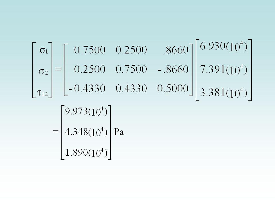
The local strains and local stress as in the 300 ply at the top surface are found using transformation Equation (2.94) as
 as")
40
Table 4.3 Local strains (m/m) in Example 4.3
Ply # Position ε1 ε2 γ12 1 (00) Top Middle Bottom 8.944 (10-8) 1.637 (10-7) 2.380 (10-7) 5.955(10-6) 5.134(10-6) 4.313(10-6) -3.836(10-6) -2.811(10-6) -1.785(10-6) 2 (300) 4.837(10-7) 7.781(10-7) 1.073(10-6) 4.067(10-6) 3.026(10-6) 1.985(10-6) 2.636(10-6) 2.374(10-6) 2.111(10-6) 3 (-450) 1.396(10-6) 5.096(10-7) -3.766(10-7) 1.661(10-6) 1.800(10-6) 1.940(10-6) -2.284(10-6) -1.388(10-6) -4.928(10-7)
 Top. Middle. Bottom (10-8) (10-7) (10-7) 5.955(10-6) 5.134(10-6) 4.313(10-6) (10-6) (10-6) (10-6) 2 (300) 4.837(10-7) 7.781(10-7) 1.073(10-6) 4.067(10-6) 3.026(10-6) 1.985(10-6) 2.636(10-6) 2.374(10-6) 2.111(10-6) 3 (-450) 1.396(10-6) 5.096(10-7) (10-7) 1.661(10-6) 1.800(10-6) 1.940(10-6) (10-6) (10-6) (10-7)")
42
Table 4.4 Local stresses (Pa) in Example 4.3
Ply # Position σ1 σ2 τ12 1 (00) Top Middle Bottom 3.351 (104) 4.464 (104) 5.577 (104) 6.188 (104) 5.359(104) 4.531 (104) (104) (104) (104) 2 (300) 9.973 (104) 1.502 (105) 2.007 (105) 4.348 (104) 3.356 (104) 2.364 (104) 1.890 (104) 1.702 (104) 1.513 (104) 3 (-450) 2.586 (105) 9.786 (104) (104) 2.123 (104) 2.010 (104) 1.898 (104) (104) (103) (103)
 Top. Middle. Bottom (104) (104) (104) (104) 5.359(104) (104) (104) (104) (104) 2 (300) (104) (105) (105) (104) (104) (104) (104) (104) (104) 3 (-450) (105) (104) (104) (104) (104) (104) (104) (103) (103)")
43
D) The portion of the load Nx taken by each ply can be calculated by integrating the stress through the thickness of each ply. However, since the stress varies linearly through each ply, the portion of the load Nx taken is simply the product of the stress at the middle of each ply (See Table 4.2) and the thickness of the ply. Portion of load Nx taken by 00 ply = 4.464(104)(5)(10-3) = N/m Portion of load Nx taken by 300 ply = 1.063(105)(5)(10-3) = N/m Portion of load Nx taken by -450 ply = 4.903(104)(5)(10-3) = N/m The sum total of the loads shared by each ply is 1000 N/m, ( ) which is the applied load in the x-direction, Nx.
(5)(10-3) = N/m. Portion of load Nx taken by 300 ply = 1.063(105)(5)(10-3) = N/m. Portion of load Nx taken by -450 ply = 4.903(104)(5)(10-3) = N/m. The sum total of the loads shared by each ply is 1000 N/m, ( ) which is the applied load in the x-direction, Nx.")
44
Percentage of load Nx taken by 00 ply

45
Figure 4.8

Similar presentations