Download presentation
Presentation is loading. Please wait.

1
11.3 - RISC Instruction Pipelines and Register Windows
By: Andy Le CS147 – Dr. Sin-Min Lee San Jose State University, Fall 2003

2
Outline Quick Review of RISC Instruction Pipelines
Register Windowing and Renaming Practical Perspective

3
What is RISC? RISC is an acronym for Reduced Instruction Set Computers
An opponent of the RISC processor is CISC which is Complex Instruction Set Computers. Goals of these 2 are to improve system performance.

4
What is RISC? (continued)
CISC and RISC differ in complexities of their instruction sets where CISC is more complex than RISC. The reduced number and complexity of instructions of the instruction sets of RISC processors are the basis for the improved performance. For example, the smaller instruction set allows a designer to implement a hardwired control unit which runs at a higher clock rate than its equivalent micro sequenced control unit.

5
Instruction Pipeline A pipeline is like an assembly line in which many products are being worked on simultaneously each at different station. With a RISC processor, 1 instruction is executed while the next is being decoded and its operands are being loaded while the following instruction is being fetched all at the same time.

6
Instruction Pipeline (continued)
By overlapping these operations, the CPU executes 1 instruction per clock cycle even though each instruction requires 3 cycles for fetch, decode, and execute.

7
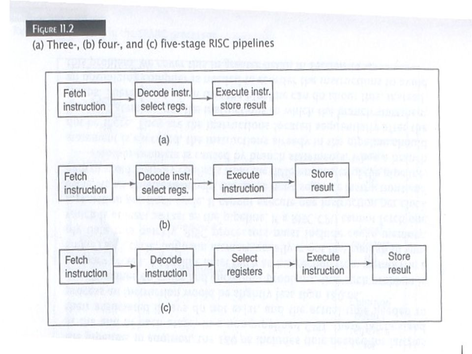
Instruction Pipeline stages
Recall the assembly line example. An instruction pipeline processes an instruction the same way the assembly line assembles a product (i.e. a car). Typical 4 stage pipeline: Stage 1: Fetches instruction from memory. Stage 2: Decodes instruction and fetches any required operands Stage 3: Executes instructions Stage 4: Stores results Each stage processes instructions simultaneously after a delay to fill the pipeline; this allows CPU to execute 1 instruction per clock cycle.
. Typical 4 stage pipeline: Stage 1: Fetches instruction from memory. Stage 2: Decodes instruction and fetches any required operands. Stage 3: Executes instructions. Stage 4: Stores results. Each stage processes instructions simultaneously after a delay to fill the pipeline; this allows CPU to execute 1 instruction per clock cycle.")
9
Instruction Pipeline Stages (continued)
Numerous stages between different CPU First RISC computer was an IBM 801 which used 4-stage instruction pipeline RISC II processor used 3-stages MIPS uses 5-stage pipeline

10
Instruction Pipeline (Advantages of)
We could use several control units for processing instructions but a single pipelined control unit offers some advantages Reduces requirement of hardware pipeline Each stage performs only a portion of the pipeline stages and that no stage needs to incorporate a complete hardware control unit Each stage only needs the hardware associated with its specific task.

11
Instruction Pipelines (Example of an advantage)
The instruction-fetch stage only needs to read an instruction from memory. This stage does not need the hardware used to decode or execute instructions Similarly, a stage that decodes instructions does not access memory; the instruction-fetch stage has already loaded the instruction from memory into an instruction register for use at the decode stage

12
Instruction Pipelines (Example of an advantage)
Another advantage of instruction pipelines is the reduced complexity of the memory interface If each stage had a complete control unit, ALL stages can access the memory and it can cause memory access conflicts in which the CPU must take care of. In general practice, RISC CPU have their memory partitioned into instruction and data modules

13
Instruction Pipeline (Example of an advantage)
The instruction-fetch stage reads data only from the instruction memory module; at all other times, it is dealing with data in registers The execute-instruction stage only access memory when it is reading data from the data memory module. Custom designed memory can be configured to allow simultaneous read/write access to different locations while avoiding memory access conflicts by the execute-instruction and store-results stages of the pipeline

14
Pipeline Clock Rate The clock rate of the pipeline and the CPU is limited to its slowest stage. Example: 4 stage pipeline with delays of 20ns, 20ns, 100ns, 40ns. The clock period must be at least 100ns to handle the delay at the 3rd stage (100ns). This results in a maximum clock rate of 10MHz. When ALL stages have same delay time, the pipeline will achieve maximum performance
. This results in a maximum clock rate of 10MHz. When ALL stages have same delay time, the pipeline will achieve maximum performance.")
15
Pipeline Clock Rate To improve pipeline performance, CPU designers use different number of stages in their instruction pipelines. The execute stage is divided into 2 sequential stages in some CPUs.

16
Pipeline Clock Rate Recall the 4 stage pipeline example (20,20,100,40 ns) Assume the 3rd stage (100ns) execute-instruction stage can be divided into 2 sequential stages to 50ns each. The pipeline will have 1 more additional stage totaling 5 stages with delays of 20,20,50,50, 40 ns. The clock period would be reduced to 50ns and clock frequency is doubled to 20MHz
 execute-instruction stage can be divided into 2 sequential stages to 50ns each. The pipeline will have 1 more additional stage totaling 5 stages with delays of 20,20,50,50, 40 ns. The clock period would be reduced to 50ns and clock frequency is doubled to 20MHz.")
17
Pipeline Clock Rate Sometimes we can use this same logic from the previous example to reduce the number of stages in a pipeline. In the 5 stage pipeline, we can combine stages 1 and 2 (20ns each) into a single stage with a delay of 40ns. Now the pipeline has 4 stages with delays of 40, 50, 50, 40ns. Combining the first 2 stages slightly reduces the hardware complexity w/o reducing clock frequency. Having 1 less stage allows the pipeline to fill and produce results starting 1 clock cycle earlier.
 into a single stage with a delay of 40ns. Now the pipeline has 4 stages with delays of 40, 50, 50, 40ns. Combining the first 2 stages slightly reduces the hardware complexity w/o reducing clock frequency. Having 1 less stage allows the pipeline to fill and produce results starting 1 clock cycle earlier.")
18
Pipeline Clock Rate The pipeline offers significant performance improvement over non-pipelined CPU. The speedup is the ratio of the time needed to process n instructions using a non-pipelined control unit to the time needed using a pipelined control unit.

19
Speedup ratio The speedup ratio (Sn) is expressed by this formula:
Sn = n * T1 / (n + k – 1) * Tk n = number of instructions T1 = time needed to process 1 instruction (non-pipeline) k = number of stages in the pipeline Tk = clock period of the pipeline
 * Tk. n = number of instructions. T1 = time needed to process 1 instruction (non-pipeline) k = number of stages in the pipeline. Tk = clock period of the pipeline.")
20
Speedup Ratio Example Sn = n * 180 / (n + 4 – 1) * 50
Let T1 = 180 ns (time needed to process 1 instruction) k = 4 (stages in the pipeline) Tk = 50 ns (clock period of the pipeline) Applying the formula: Sn = n * 180 / (n + 4 – 1) * 50 For steady state (n ∞), the maximum speedup is Sn = 180 / 50 3.6
 k = 4 (stages in the pipeline) Tk = 50 ns (clock period of the pipeline) Applying the formula: Sn = n * 180 / (n + 4 – 1) * 50. For steady state (n ∞), the maximum speedup is Sn = 180 / 50 3.6.")
21
Speedup Ratio Example In reality, the speedup would be slightly less than this for 2 reasons. 1st reason, this does not account for the first few cycles needed to fill the pipeline; in addition the 180ns includes the time needed for the latches at the end of each stage. In a non-pipelined CPU, these latches and their associated delays do not exist and the actual time needed to process an instruction would be slightly less than 180ns.

22
Speedup Ratio Example Pipelines do cause and encounter problems. One problem is memory access. A pipeline must fetch an instruction from memory in a single clock cycle but main memory usually is not fast enough to supply data quickly. RISC processors must include cache memory which is at least as fast as the pipeline. If the RISC CPU cannot fetch 1 instruction per clock cycle, it cannot execute 1 instruction per clock cycle. The cache must separate instructions and data to prevent memory conflicts from different stages of the pipeline.

23
Speedup Ratio Example 2nd problem is caused by branch statements. When a branch statement is executed, the instructions already in the pipeline should not exist. They are instructions located sequentially after the branch statement and not the instructions to which the branch statement jumps. There is not much that the pipeline can do about this but instead an optimizing compiler is needed to reorder the instructions to avoid this problem.

24
11.3.2 Register Windowing and Renaming
The reduced hardware requirements of RISC processors leave additional space available on the chip for the system designer. RISC CPUs generally use this space to include a large number of registers ( > 100 occasionally). The CPU can access data in registers more quickly than data in memory so having more registers makes more data available faster. Having more registers also helps reduce the number of memory references especially when calling and returning from subroutines.
. The CPU can access data in registers more quickly than data in memory so having more registers makes more data available faster. Having more registers also helps reduce the number of memory references especially when calling and returning from subroutines.")
25
Register Windowing and Renaming
The RISC processor may not be able to access all the registers it has at any given time provided that it has many of it. Most RISC CPUs have some global registers which are always accessible. The remaining registers are windowed so that only a subset of the registers are accessible at any specific time.

26
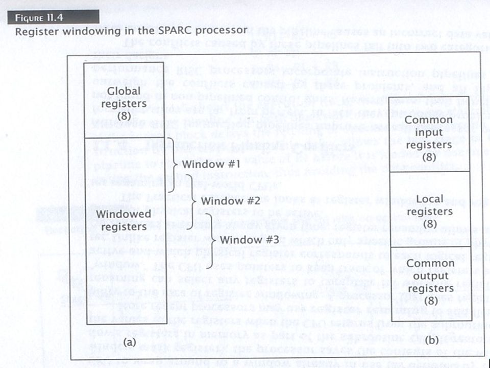
Register Windows To understand how register windows work, we consider the windowing scheme used by the Sun SPARC processor. The processor can access any of the 32 different registers at a given time. (The instruction formats for SPARC always use 5 bits to select a source/destination register which can take any 32 different values. Of these 32 registers, 8 are global registers that are always accessible. The remaining 24 registers are contained in the register window.

27
Register Window On figure 11.4, the register window overlap. The overlap consists of 8 registers in SPARC CPU. Notice that the organization of the windows are supposed to be circular and not linear; meaning that the last window overlaps with the first window. Example: the last 8 registers of window 1 are also the first 8 registers of window 2. Similarly, the last 8 registers of window 2 are also the first 8 registers of window 3. The middle 8 registers of window 2 are local; they are not shared with any other window.

29
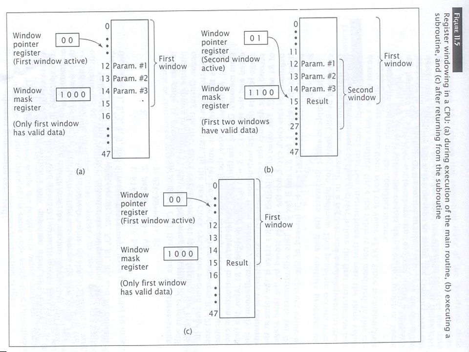
Register Window The RISC CPU must keep track of which window is active and which windows contain valid data. A window pointer register contains the value of the window that is currently active. A window mask register contains 1 bit per window and denotes which windows contains valid data.

30
Register Window Register windows provide their greatest benefit when the CPU calls a subroutine. During the calling process, the register window is moved down 1 window position. In the SPARC CPU, if window 1 is active and the CPU calls a subroutine, the processor activates window 2 by updating the window pointer and window mask registers. The CPU can pass parameters to the subroutine via the registers that overlap both windows instead of memory. This saves a lot of time when accessing data. The CPU can use the same registers to return results to the calling routine.

31
Register Window Example
Example: A CPU with 48 registers. The CPU has 4 windows with 16 registers each and an overlap of 4 registers between windows. Initially the CPU is running a program using the 1st register window (shown in 11.5a). It must call a subroutine and pass 3 parameters to the subroutine. The CPU stores these parameters in 3 of the 4 overlapping registers and calls the subroutine. Figure 11.5b shows the state of the CPU while the subroutine is active. The subroutine can directly access the parameters. Now the subroutine calculates a result to be returned to the main program. The deactivates the 2nd window; the CPU now works with the 1st window as shown in figure 11.5c and can directly access the result.
. It must call a subroutine and pass 3 parameters to the subroutine. The CPU stores these parameters in 3 of the 4 overlapping registers and calls the subroutine. Figure 11.5b shows the state of the CPU while the subroutine is active. The subroutine can directly access the parameters. Now the subroutine calculates a result to be returned to the main program. The deactivates the 2nd window; the CPU now works with the 1st window as shown in figure 11.5c and can directly access the result.")
33
Register Windows Most RISC processors that use register windowing have about 8 windows which is sufficient for the vast majority of programs to handle subroutine calls. Besides recursive subroutines, it is unusual for a program to go beyond 8 levels of calls. However it is possible for the level of calls to exceed the number of windows and the CPU must be able to handle this situation.

34
Register Renaming More recent processors may use register renaming to add flexibility to the idea of register windowing. A processor that uses register renaming can select any registers to create its working register “window.” The CPU uses pointers to keep track of which registers are active and which physical register corresponds to each logical register.

35
Register Renaming Unlike register windowing, in which only specific groups of physical registers are active at any given time, register renaming allows any group of physical registers to be active. The Practical Perspective looks at register windowing and register renaming in real-world CPUs.

36
Practical Perspective
Both register windowing and register renaming are used in modern processors. In addition to SPARC processors, the RISC II processor uses register windowing. The RISC II processor has 138 registers; 10 are global and the rest are windowed. Each of its 8 windows contain 22 registers: 6 common input, 10 local, and 6 common output. The UltraSPARC III processor also uses register windowing. The MIPS R10000 on the other hand uses register renaming. Intel’s Itanium processor takes a unique approach. It has 128 integer registers, 32 of which are global. The remaining 96 registers are windowed, but the size of the window is not fixed; their size can be varied depending on the needs of the program under execution.

37
Happy Thanksgiving Day!!!

Similar presentations


Define pipelining 2)Calculate the speedup achieved by pipelining for a given number of instructions. 3)Define how pipelining improves.>")


 element by element to produce an output vector. Typical array-oriented operations.>")

 Central Processing Unit (CPU) Basics CHAPTER 13: REDUCED INSTRUCTION SET COMPUTERS (RISC) 1.>")

 CS 147 Li-Chuan Fang.>")