Download presentation
Presentation is loading. Please wait.

1
ECE 382 Lesson 32 Lesson Outline Lab 6 Introduction Pulse Width Modulation Capture / Compare Example Lab 6 Tips Admin Lab#6 “prelab” due BOC lesson 33 Note ***Includes Schematic and Flowgraph!

2
Lab#6: Robot Motion Prelab: -Software Design (flowchart and/or pseudo-code) -Hardware Schematics Basic Functionality: -Move the Robot Forward, Reverse, Left, Right (small and large turn) (no USB cord) A Functionality: -Move the Robot Forward, Reverse, Left, Right using the IR remote control
 -Hardware Schematics Basic Functionality: -Move the Robot Forward, Reverse, Left, Right (small and large turn) (no USB cord) A Functionality: -Move the Robot Forward, Reverse, Left, Right using the IR remote control")
3
Using DC Motors How do DC motors work? How do you make them go faster?

4
Using DC Motors How do DC motors work? How do you make them go faster? –Provide analog DC voltage… The higher the voltage, the faster it spins –[ motor demo ]

5
Using DC Motors How do DC motors work? How do you make them go faster? –Provide analog DC voltage… The higher the voltage, the faster it spins –[ motor demo ] How to we control a DC motor with the MSP430 ? Can we use the ADC converter?

6
Using DC Motors How do DC motors work? How do you make them go faster? –Provide analog DC voltage… The higher the voltage, the faster it spins –[ motor demo ] How to we control a DC motor with the MSP430 ? Can we use the ADC converter? Two issues interfacing MSP430 with a DC motor?

7
Using DC Motors How do DC motors work? How do you make them go faster? –Provide analog DC voltage… The higher the voltage, the faster it spins –[ motor demo ] How to we control a DC motor with the MSP430 ? Can we use the ADC converter? Two issues interfacing MSP430 with a DC motor? –MSP430 only produces two voltages (Vcc and Gnd) Solution?.
 Solution ..")
8
Using DC Motors How do DC motors work? How do you make them go faster? –Provide analog DC voltage… The higher the voltage, the faster it spins –[ motor demo ] How to we control a DC motor with the MSP430 ? Can we use the ADC converter? Two issues interfacing MSP430 with a DC motor? –MSP430 only produces two voltages (Vcc and Gnd) Solution? PWM- pulse width modulation (remember this?)
 Solution. PWM- pulse width modulation (remember this ).")
9
Using DC Motors How do DC motors work? How do you make them go faster? –Provide analog DC voltage… The higher the voltage, the faster it spins –[ motor demo ] How to we control a DC motor with the MSP430 ? Can we use the ADC converter? Two issues interfacing MSP430 with a DC motor? –MSP430 only produces two voltages (Vcc and Gnd) Solution? PWM- pulse width modulation (remember this?) –MSP430 does not source enough current to power the motors (blow the chip)
 Solution. PWM- pulse width modulation (remember this ) –MSP430 does not source enough current to power the motors (blow the chip).")
10
Using DC Motors How do DC motors work? How do you make them go faster? –Provide analog DC voltage… The higher the voltage, the faster it spins –[ motor demo ] How to we control a DC motor with the MSP430 ? Can we use the ADC converter? Two issues interfacing MSP430 with a DC motor? –MSP430 only produces two voltages (Vcc and Gnd) Solution? PWM- pulse width modulation (remember this?) –MSP430 does not source enough current to power the motors (blow the chip) Solution?
 Solution. PWM- pulse width modulation (remember this ) –MSP430 does not source enough current to power the motors (blow the chip) Solution .")
11
Using DC Motors How do DC motors work? How do you make them go faster? –Provide analog DC voltage… The higher the voltage, the faster it spins –[ motor demo ] How to we control a DC motor with the MSP430 ? Can we use the ADC converter? Two issues interfacing MSP430 with a DC motor? –MSP430 only produces two voltages (Vcc and Gnd) Solution? PWM- pulse width modulation (remember this?) –MSP430 does not source enough current to power the motors (blow the chip) Solution? Motor driver chip (SN754410) MSP430 Timer system helps Input Capture: Monitor a pin for a specified signal (rising edge, falling edge, either edge) and record when it occurs. Output Compare: Generate a specified signal with precise timing. (can make a PWM signal) Do Not Exceed the 1A current rating (i.e. ~60% Duty Cycle)
 Solution. PWM- pulse width modulation (remember this ) –MSP430 does not source enough current to power the motors (blow the chip) Solution. Motor driver chip (SN754410) MSP430 Timer system helps Input Capture: Monitor a pin for a specified signal (rising edge, falling edge, either edge) and record when it occurs. Output Compare: Generate a specified signal with precise timing. (can make a PWM signal) Do Not Exceed the 1A current rating (i.e. ~60% Duty Cycle).")
12
Timer Block Diagram 0 1 2 3 4 5 clkscnts Family User Guide pp 357 Blue Book pp 46 Capture / Compare

13
Backup Slides Family User Guide pp 372 Blue Book pp 53

14
Timer Block Diagram Family User Guide pp 357 Blue Book pp 46 CAP

15
Input Capture Capture mode is selected when the CAP bit in TACCTL is set to 1. It's used to record time events. It can be used for: –Event detection –Event counting –Pulse-width measurement –Frequency measurement Each TACCRx has two possible capture pins - CCIxA and CCIxB. The one being monitored is selectable by software. If a capture occurs: - The TAR value is copied into the TACCRx register - The interrupt flag CCIFG is set Family User Guide pp 363 Blue Book pp 49

16
Backup Slides Family User Guide pp 372 Blue Book pp 53

17
Timer Block Diagram CCISx Family User Guide pp 357 Blue Book pp 46 SCS CMx CCIFG

18
Input Capture The input signal level can be read at any time via the CCI bit. MSP430x2xx family devices may have different signals connected to CCIxA and CCIxB. See the device-specific data sheet for the connections of these signals. Family User Guide pp 362 Blue Book pp 48

19
Input Capture The input signal level can be read at any time via the CCI bit. MSP430x2xx family devices may have different signals connected to CCIxA and CCIxB. See the device-specific data sheet for the connections of these signals. Device Specific pp 16 Blue Book pp 112

20
Backup Slides Family User Guide pp 372 Blue Book pp 53

21
Input Capture Device Specific pp 43 Blue Book pp 124

22
Output Compare Compare mode is selected when the CAP bit in TACCTL is set to 0 Same Timer Modes: MCx Count up to TACCRO. Now adding two new registers: TA0CCR1 and TA0CCR2 McxModeDescription 00Stop The timer is halted. MC_0 01Up The timer repeatedly counts from zero to the value of TACCR0. MC_1 10Continuous The timer repeatedly counts from zero to 0FFFFh. MC_2 11Up/downThe timer repeatedly counts from zero up to the value of TACCR0 and back down to zero. MC_3

23
Timer Block Diagram Family User Guide pp 357 Blue Book pp 46 CCR0-2

24
Output Compare You will likely use mode 3 & 7 for PWM

25
Example #include int main(void) { WDTCTL = WDTPW|WDTHOLD; // stop the watchdog timer P1DIR |= BIT2; // TA0CCR1 on P1.2 P1SEL |= BIT2; // TA0CCR1 on P1.2 TA0CTL &= ~MC1|MC0; // stop timer A0 TA0CTL |= TACLR; // clear timer A0 TA0CTL |= TASSEL1; // configure for SMCLK TA0CCR0 = 100; // set signal period to 100 clock cycles (~100 microseconds ) TA0CCR1 = 25; // set duty cycle to 25/100 (25%) TA0CCTL1 |= OUTMOD_7; // set TACCTL1 to Reset / Set mode TA0CTL |= MC0; // count up while (1) { __delay_cycles(1000000); TA0CCR1 = 50; // set duty cycle to 50/100 (50%) __delay_cycles(1000000); TA0CCR1 = 75; // set duty cycle to 75/100 (75%) __delay_cycles(1000000); TA0CCR1 = 100; // set duty cycle to 100/100 (100%) __delay_cycles(1000000); TA0CCR1 = 25; // set duty cycle to 25/100 (25%) } return 0; }
 { WDTCTL = WDTPW|WDTHOLD; // stop the watchdog timer P1DIR |= BIT2; // TA0CCR1 on P1.2 P1SEL |= BIT2; // TA0CCR1 on P1.2 TA0CTL &= ~MC1|MC0; // stop timer A0 TA0CTL |= TACLR; // clear timer A0 TA0CTL |= TASSEL1; // configure for SMCLK TA0CCR0 = 100; // set signal period to 100 clock cycles (~100 microseconds ) TA0CCR1 = 25; // set duty cycle to 25/100 (25%) TA0CCTL1 |= OUTMOD_7; // set TACCTL1 to Reset / Set mode TA0CTL |= MC0; // count up while (1) { __delay_cycles( ); TA0CCR1 = 50; // set duty cycle to 50/100 (50%) __delay_cycles( ); TA0CCR1 = 75; // set duty cycle to 75/100 (75%) __delay_cycles( ); TA0CCR1 = 100; // set duty cycle to 100/100 (100%) __delay_cycles( ); TA0CCR1 = 25; // set duty cycle to 25/100 (25%) } return 0; }")
26
Example with Interrupt #include void main(void) { WDTCTL = WDTPW|WDTHOLD;// stop the watchdog timer P2DIR |= BIT1; // TA1CCR1 on P2.1 P2SEL |= BIT1; // TA1CCR1 on P2.1 P2OUT &= ~BIT1; TA1CTL |= TASSEL_2|MC_1|ID_0; // configure for SMCLK P1DIR |= BIT0; //use LED to indicate duty cycle has toggled P1REN |= BIT3; P1OUT |= BIT3; TA1CCR0 = 1000; // set signal period to 1000 clock cycles (~1 millisecond) TA1CCR1 = 250; // set duty cycle to 250/1000 (25%) TA1CCTL0 |= CCIE; // enable CC interrupts TA1CCTL1 |= OUTMOD_7|CCIE; // set TACCTL1 to Set / Reset mode//enable CC interrupts TA1CCTL1 &= ~CCIFG; //clear capture compare interrupt flag _enable_interrupt(); while (1) { while (P1IN & BIT3); //every time the button is pushed, toggle the duty cycle __delay_cycles(1000000); TA1CCR1 = 1000; // set duty cycle to 1000/1000 (100%) while (P1IN & BIT3); __delay_cycles(1000000); TA1CCR1 = 750; // set duty cycle to 750/1000 (75%) while (P1IN & BIT3); __delay_cycles(1000000); TA1CCR1 = 500; // set duty cycle to 500/1000 (50%) while (P1IN & BIT3); __delay_cycles(1000000); TA1CCR1 = 250; // set duty cycle to 250/1000 (25%) while (P1IN & BIT3); __delay_cycles(1000000); TA1CCR1 = 100; // set duty cycle to 100/1000 (10%) while (P1IN & BIT3); __delay_cycles(1000000); TA1CCR1 = 20; // set duty cycle to 20/1000 (2%) } #pragma vector = TIMER1_A0_VECTOR // This is from the MSP430G2553.h file __interrupt void captureCompareInt (void) { P1OUT |= BIT0; //Turn on LED // Disable Timer A Interrupt TA1CCTL1 &= ~CCIFG; //clear capture compare interrupt flag // TACTL &= ~TAIFG; } #pragma vector = TIMER1_A1_VECTOR // This is from the MSP430G2553.h file __interrupt void captureCompareInt2 (void) { P1OUT &= ~BIT0; //Turn off LED // Disable Timer A Interrupt TA1CCTL1 &= ~CCIFG; //clear capture compare interrupt flag // TACTL &= ~TAIFG; }
 { WDTCTL = WDTPW|WDTHOLD;// stop the watchdog timer P2DIR |= BIT1; // TA1CCR1 on P2.1 P2SEL |= BIT1; // TA1CCR1 on P2.1 P2OUT &= ~BIT1; TA1CTL |= TASSEL_2|MC_1|ID_0; // configure for SMCLK P1DIR |= BIT0; //use LED to indicate duty cycle has toggled P1REN |= BIT3; P1OUT |= BIT3; TA1CCR0 = 1000; // set signal period to 1000 clock cycles (~1 millisecond) TA1CCR1 = 250; // set duty cycle to 250/1000 (25%) TA1CCTL0 |= CCIE; // enable CC interrupts TA1CCTL1 |= OUTMOD_7|CCIE; // set TACCTL1 to Set / Reset mode//enable CC interrupts TA1CCTL1 &= ~CCIFG; //clear capture compare interrupt flag _enable_interrupt(); while (1) { while (P1IN & BIT3); //every time the button is pushed, toggle the duty cycle __delay_cycles( ); TA1CCR1 = 1000; // set duty cycle to 1000/1000 (100%) while (P1IN & BIT3); __delay_cycles( ); TA1CCR1 = 750; // set duty cycle to 750/1000 (75%) while (P1IN & BIT3); __delay_cycles( ); TA1CCR1 = 500; // set duty cycle to 500/1000 (50%) while (P1IN & BIT3); __delay_cycles( ); TA1CCR1 = 250; // set duty cycle to 250/1000 (25%) while (P1IN & BIT3); __delay_cycles( ); TA1CCR1 = 100; // set duty cycle to 100/1000 (10%) while (P1IN & BIT3); __delay_cycles( ); TA1CCR1 = 20; // set duty cycle to 20/1000 (2%) } #pragma vector = TIMER1_A0_VECTOR // This is from the MSP430G2553.h file __interrupt void captureCompareInt (void) { P1OUT |= BIT0; //Turn on LED // Disable Timer A Interrupt TA1CCTL1 &= ~CCIFG; //clear capture compare interrupt flag // TACTL &= ~TAIFG; } #pragma vector = TIMER1_A1_VECTOR // This is from the MSP430G2553.h file __interrupt void captureCompareInt2 (void) { P1OUT &= ~BIT0; //Turn off LED // Disable Timer A Interrupt TA1CCTL1 &= ~CCIFG; //clear capture compare interrupt flag // TACTL &= ~TAIFG; }")
27
Ports? Pin 3 TA0.0 P1.1 Pin 4 TA0.1 P1.2 Pin 8 TA1.0 P2.0 Pin 9 TA1.1 P2.1

28
pp 109 of Blue Bookpp 11 of Device Specific

29
Lab Tips Drives like a tank? How do you turn? Motor Driver Chip You cannot hook your MSP430 directly up to the motors - it can't supply enough current! We need to use a motor driver chip instead. It can only supply 1A per circuit! Do not exceed that! Check out the datasheet for wiring details.Check out the datasheet for wiring details. –http://ece.ninja/382/datasheets/SN754410.pdfhttp://ece.ninja/382/datasheets/SN754410.pdf Motor Stall Current This is the max current draw your motor might have - usually happens when it runs up against the wall or something. This better not exceed the 1A your motor driver chip can supply or you'll burn it! [Show technique to measure stall current] On my robot, the stall current does not go below one amp until my motor is being driven at 8V or less - roughly 60% duty cycle. Exceed this at your own risk!

30
Lab Tips Robot Guidance and Troubleshooting http://ece.ninja/382/datasheets/robot_guide.html MSP430 In-Circuit Supplying Power –We have 3.3V regulators! Use them! If you try to give 5V to your MSP430, you will fry it! Check out the datasheet for wiring details.Check out the datasheet for wiring details. –http://ece.ninja/382/datasheets/LD1117V33.pdfhttp://ece.ninja/382/datasheets/LD1117V33.pdf Wiring it up –http://ece.ninja/382/datasheets/robot.htmlhttp://ece.ninja/382/datasheets/robot.html Programming –See the tutorial on the website! You can just jump the VCC / TEST / RESET signal over to the chip on the breadboard. –http://ece.ninja/382/datasheets/in_circuit_programming.htmlhttp://ece.ninja/382/datasheets/in_circuit_programming.html –http://ece.ninja/382/datasheets/standalone.htmlhttp://ece.ninja/382/datasheets/standalone.html Chip Reset Due to Current Fluctuation –If the motors draw a large amount of current (due to stall), there is a good chance it will interfere with the current provided to your MSP430. To combat this, you can put a large capacitor across the 5V rail (between power and ground). This will supplement the lost current and prevent your chip from being reset.
, there is a good chance it will interfere with the current provided to your MSP430. To combat this, you can put a large capacitor across the 5V rail (between power and ground). This will supplement the lost current and prevent your chip from being reset..")
31
Lab Details http://ece.ninja/382/labs/lab6/index.html

32
Backup slides

33
Timer ( p 355 User’s Guide )
")
34
Multiplexing Only 20 Pins !!! But want access to many more signals –Therefore, each pin shares several signals multiplexing Use PxSEL1 and PxSEL2 to select signal for each pin –The details are in the MSP430G2x53 2x13 Mixed Signal MCU Datasheet.MSP430G2x53 2x13 Mixed Signal MCU Datasheet

35
Pitfall !!!

37
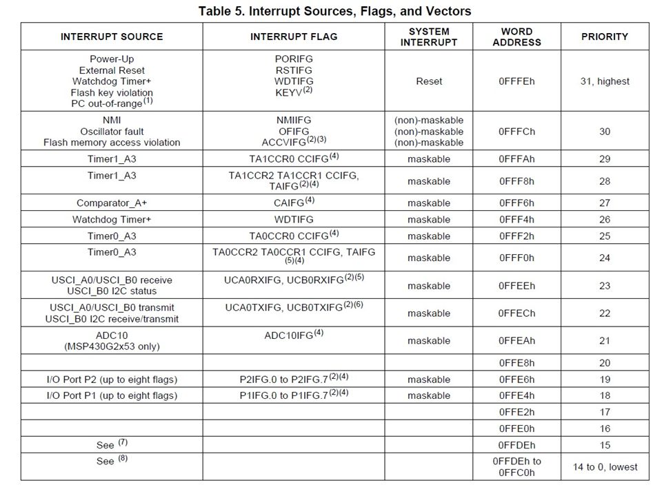
Interrupt Vector Table

Similar presentations

>")


