Download presentation
Presentation is loading. Please wait.

1
Principles of light microscopy: With a compound light microscope, we can examine very small specimens as well as some of their fine detail. A series of finely round lenses form a clearly focused image that is many times larger than the specimen itself. The magnification is achieved when light rays from an illuminator, the light source pass through the condenser, which has lenses that direct the light source, pass through the specimen. From here light rays pass into the objective lenses, the lenses closer to the specimen. The image of the specimen is magnified again by the ocular lens, or eyepiece. Magnification The overall magnification is given as the product of the lenses and the distance over which the image is projected: M = D. M1.M2/250 mm where: D = projection (tube) length (usually = 250 mm); M1, M2 = magnification of objective and ocular. 250 mm = minimum distance of distinct vision for 20/20 eyes.
 length (usually = 250 mm); M1, M2 = magnification of objective and ocular. 250 mm = minimum distance of distinct vision for 20/20 eyes..")
3
Resolution: Resolution (also called the resolving power) is the ability of the lenses to distinguish fine detail and structure. Specifically it refers to the ability of the lenses to distinguish between two points a specified distance apart. For example if the resolving power of a microscope is 0.4 nm, it can distinguish between two points if they are at least 0.4 nm apart.

4
Contrast: To obtain a clear, finely detailed image under a compound microscope, specimen must be made to contrast sharply with their medium (substance in which they are suspended). To attain such contrast, we must change the refractive index of specimens from that of their medium. The refractive index is a measure of the light bending ability of a medium. The refractive index of specimens can be changed by staining the later. Light rays move in a straight line through a single medium. After staining when light rays pass through two materials (the specimen and its medium) with different refractive indexes, the rays changes direction (refract) from a straight path by bending or changing an angle at the boundary between the materials and increase the image contrast between the specimen and the medium as the light rays travel away from the specimen, they spread out and enter the objective lens, and the image is thereby magnified.
 with different refractive indexes, the rays changes direction (refract) from a straight path by bending or changing an angle at the boundary between the materials and increase the image contrast between the specimen and the medium as the light rays travel away from the specimen, they spread out and enter the objective lens, and the image is thereby magnified..")
5
Brightness contrast arises from different degrees of absorption at different points in the specimen. Color contrast can also arise from absorption when the degree of absorption depends on the wavelength and varies from point to point in the specimen. Phase contrast arises from a shift in the phase of the light as a resultof interaction with the specimen. Fluorescence contrast arises when the incident light is absorbed and partially reemitted at a different wavelength.

6
Bright Field Microscopy Principle Light from an incandescent source is aimed toward a lens beneath the stage called the condenser, through the specimen, through an objective lens, and to the eye through a second magnifying lens, the ocular or eyepiece. The condenser is used to focus light on the specimen through an opening in the stage. After passing through the specimen, the light is displayed to the eye with an apparent field that is much larger than the area illuminated. Typically used on thinly sectioned materials

8
Principle: Dark field microscopy To view a specimen in dark field, an opaque disc is placed underneath the condenser lens, so that only light that is scattered by objects on the slide can reach the eye. Instead of coming up through the specimen, the light is reflected by particles on the slide. Everything is visible regardless of color, usually bright white against a dark background.

9
Principle: Phase contrast microscopy Phase contrast microscopy is an optical microscopy illumination technique in which small phase shifts in the light passing through a transparent specimen are converted into amplitude or contrast changes in the image.optical microscopyilluminationphase shiftsamplitudecontrast A phase contrast microscope does not require staining to view the slide. This type of microscope made it possible to study the cell cycle.microscopestainingcell cycle As light travels through a medium other than vacuum, interaction with this medium causes its amplitude and phase to change in a way which depends on properties of the medium. Changes in amplitude give rise to familiar absorption of light which gives rise to colours which is wavelength dependent. The human eye measures only the energy of light arriving on the retina, so changes in phase are not easily observed, yet often these changes in phase carry a large amount of information.vacuumamplitudephase http://web.utk.edu/~prack/MSE%20300/Lightmicroscopyhandout.pdf http://en.wikipedia.org/wiki/Phase_contrast_microscopy

10
Principle of Transmission electron Microscopy In electron microscopy, a beam of electron is used instead of light. The better resolution of electron microscope is due to the shorter wavelength of electrons; Wavelengths of electrons are 100,000 times shorter than the wavelengths of visible light. In the transmission electron microscope a finely focused beam of electrons from a electron gun passes through a specially prepared ultrathin section of the specimen. The beam is focused on a small area of the specimen by an electromagnetic condenser lens which direct beam of electrons in a straight line to illuminate the specimen. The specimen is usually placed on a copper mesh grid. The beam of electrons pass through the specimen and then through the electromagnetic objective lens, which magnifies the image. Finally the electrons are focused by an electromagnetic projector lens, rather than an by an ocular lens in a light microscope onto a flourescent screen or photographic plate.

12
The final image, called a transmission electron micrograph, appears as many light and dark areas, depending on the number of electrons absorbed by the different areas of the speciemen. Because most microscopic specimens are so thin the contrast between their ultrastructure and background is weak. Contrast can be greatly enhanced by using a “stain” that absorbs electrons and produces a darker image in the stained region. Salts of various heavy metals such as lead, osmium, tungsten, and uranium are commonly used as stains. These metals can be fixed in the specimen (positive staining) or used to increase the electron opacity of the surrounding field (negative staining). Negative staining is useful for the study of very smallest specimens, such as virus particles, bacterial flagella and protein molecules.
 or used to increase the electron opacity of the surrounding field (negative staining). Negative staining is useful for the study of very smallest specimens, such as virus particles, bacterial flagella and protein molecules..")
13
Scanning electron microscopy The scanning electron microscope (SEM) overcomes the problem of sectioning associated with a transmission electron microscope. A scanning electron microscope provides striking three dimensional views of specimen. In scanning electron microscopy, an electron gun produces a finely focused beam of electrons called primary electron beam. These electrons pass through pass through eletromagnetic lenses and are directed over the surface of the specimen. The primary electron beam knocks electrons out of the surface of the specimen.The primary electron beam knocks electrons out of the surface of the specimen and the secondary electrons thus produced are transmitted to an electron collector, amplified and, used to produce an image on a viewing screen or photographic plate. In practice it can resolve objects as close together as 20 nm, and objects are generally magnified 1000 to 10,000x

14
Comparison of Light (LM) and Electron Microscopes Similarities (Arrangement and function of components are similar) 1) Illumination system: produces required radiation and directs it onto the specimen. Consists of a source, which emits the radiation, and a condenser lens, which focuses the illuminating beam (allowing variations of intensity to be made) on the specimen. 2) Specimen stage: situated between the illumination and imaging systems. 3) Imaging system: Lenses which together produce the final magnified image of the specimen. Consists of i) an objective lens which focuses the beam after it passes through the specimen and forms an intermediate image of the specimen and ii) the projector lens(es) which magnifies a portion of the intermediate image to form the final image. 4) Image recording system: Converts the radiation into a permanent image (typically on a photographic emulsion) that can be viewed.
 on the specimen. 2) Specimen stage: situated between the illumination and imaging systems. 3) Imaging system: Lenses which together produce the final magnified image of the specimen. Consists of i) an objective lens which focuses the beam after it passes through the specimen and forms an intermediate image of the specimen and ii) the projector lens(es) which magnifies a portion of the intermediate image to form the final image. 4) Image recording system: Converts the radiation into a permanent image (typically on a photographic emulsion) that can be viewed..")
15
Differences between Light Microscope and Transmission Electron Microscope Light MicroscopeTransmission Electron Microscope 1.Optical lenses are generally made of glass with fixed focal lengths Magnetic lenses are constructed with ferromagnetic materials and windings of copper wire producing a focal length which can be changed by varying the current through the coil. 2Magnification in the LM is generally changed by switching between different power objective lenses mounted on a rotating turret above the specimen. It can also be changed if oculars (eyepieces) of different power are used. In the TEM the magnification (focal length) of the objective remains fixed while the focal length of the projector lens is changed to vary magnification. 3The LM has a small depth of field, thus different focal levels can be seen in the specimen. The large (relative) depth of field in the TEM means that the entire (thin) specimen is in focus simultaneously.
 of different power are used. In the TEM the magnification (focal length) of the objective remains fixed while the focal length of the projector lens is changed to vary magnification. 3The LM has a small depth of field, thus different focal levels can be seen in the specimen. The large (relative) depth of field in the TEM means that the entire (thin) specimen is in focus simultaneously..")
16
5The source is generally situated at the bottom of LMs. TEMs are generally constructed with the radiation source at the top of the instrument 6Live organism can be observedTEM is operated at high vacuum (since the mean free path of electrons in air is very small) so most specimens (biological) must be dehydrated (i.e. dead !!). 7Specimen remains UnaffectedTEM specimens (biological) are rapidly damaged by the electron beam. 8Resolution and Magnification lessTEMs can achieve higher magnification and better resolution than LMs.
 so most specimens (biological) must be dehydrated (i.e. dead !!). 7Specimen remains UnaffectedTEM specimens (biological) are rapidly damaged by the electron beam. 8Resolution and Magnification lessTEMs can achieve higher magnification and better resolution than LMs..")
17
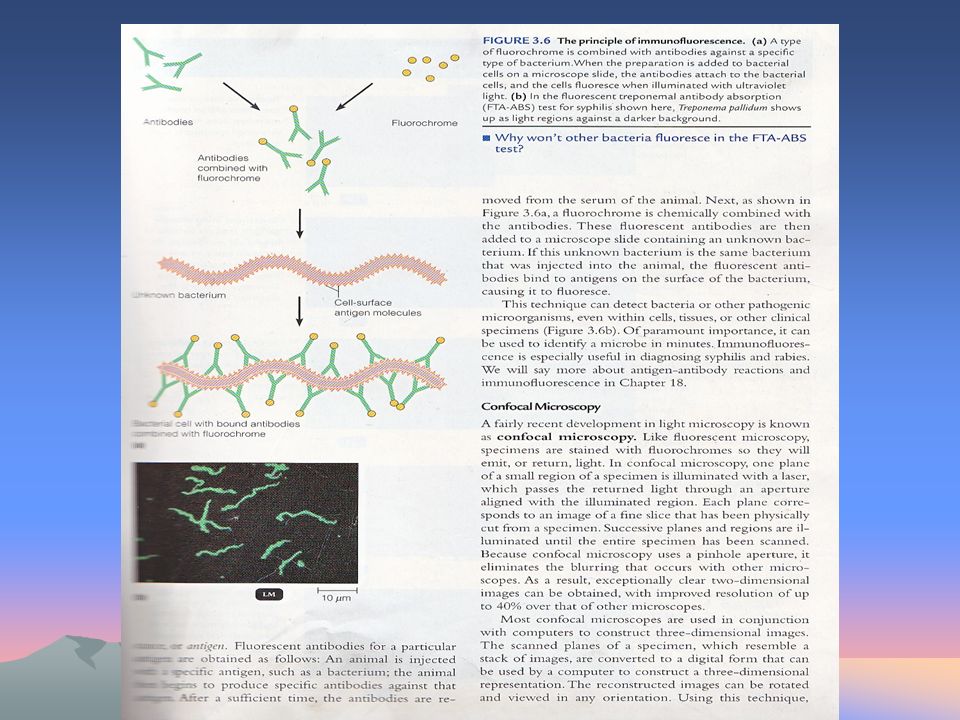
Flourescence Microscopy Flouresence microscopy takes the advantage of flourescence, the ability of substances to absorb short wavelength of light (ultraviolet) and gives off light of longer wavelength (visible). When microorganisms stained with fluorochrome are examined under a fluorescence microscope with an ultrviolet or near ultraviolet light source. Fluorochromes have special attractions for different microorganisms. For example, the fluorochrome auramine O glows yellow when exposed to ultraviolet light, is strongly absorbed by Mycobacterium tuberculosis.When the dye is applied to a sample of material suspected of containing the material of bacterium, the bacterium can be detected by the appearance of bright yellow organisms against a dark background. Bacillus anthracis appears apple green when stained with flourescencein isothiocyanate (FITC).
..")
Similar presentations


 Fluorescent U-V Electron Monocular>")


 when passing from one medium to another refractive index –a measure of how.>")


