Download presentation
Presentation is loading. Please wait.

2
BUILDING LOAD NORMAL OPERATION 1. ATS are in normal position connected to utility source 2. All generator set paralleling circuit breaker open

3
BUILDING LOAD LOSS OF NORMAL POWER 1. Upon reciept of start signal from any ATS all generators automatically and independently start. ATS 2. Any genset at normal operating condition will closed each GCB at deadbus condition 3. Succeeding genset will synchronize to the emergency bus

4
BUILDING LOAD ATS TRANSFER TO EMERGENCY POWER 1. After the preset time delay expire ATS will transfer to emergency power. ATS

6
BUILDING LOAD TOTAL LOAD IS 80% 1. All synchronized generators will share the load equally ATS

7
BUILDING LOAD 1. If the total load is reduced to 20% of the total capacity while the 2 generators are running ATS 2. The system will shut off the GCB # 2 3. Priority Genset # 1 will received the reduced load

8
BUILDING LOAD 1. Single generator is running and reached 70% of its rated capacity ATS 2. The system will start genset # 2 synchronized to online generator and share load equally

9
www.intellisyspower.com

10
BUILDING LOAD 1. When normal power return, ATS will transfer power from emergency into normal power after a preset time delay ATS NORMAL POWER RETURNS START SIGNAL 2. System start from ATS will be remove and the genset will turn off after cool down timer expires

11
www.intellisyspower.com

12
1. Before any attempt to start and parallel the generators, check that all generator paralleling circuit breaker are all in OFF position. Generator controller auto mode must be switch on. 2. Press MODE push button (SELECT SEMI-AUTO MODE) located on the front face of DEIF controller (G1 and G2) and then press START button the generator will start and ramp to rated voltage and frequency. www.intellisyspower.com Mode Button Start Button
 located on the front face of DEIF controller (G1 and G2) and then press START button the generator will start and ramp to rated voltage and frequency. Mode Button Start Button.")
13
3. Check if run and generator voltage LED illuminates, it means the generator is protected and ready. 4. Select the generator (G1 and G2) to be online first, then press CB CLOSE/OPEN button on the DEIF controller. The controller will automatically detects if it is a paralleling mode or a single mode www.intellisyspower.com CB Close/Open Button Run LED
 to be online first, then press CB CLOSE/OPEN button on the DEIF controller. The controller will automatically detects if it is a paralleling mode or a single mode CB Close/Open Button Run LED.")
14
5. To synchronize the second generator, press CB CLOSE/OPEN button on DEIF controller, the digital synchroscope will automatically display during synchronization time and then it will disappear after generator breaker closed. Available loads on the bus will automatically load share to the units online. Typically the load share percentage factor is 50 %. www.intellisyspower.com CB Close/Open Button

15
www.intellisyspower.com 6. To stop the G1 and G2 press STOP button on DEIF controller to perform engine cooling down. When the preset cool down timer elapse the engine will automatically shutdown. Stop Button

16
www.intellisyspower.com

17
GCB Fail to Close Probable Cause Circuit Breaker control CB tripped off GCB Closing relay defective (3XG) Circuit Breaker Spring Discharged Defective closing coil, de –energized Controller relay output defective GCB control transformer defective or no output Corrective Action Check GCB control circuit, reset control CB Replace defective closing relay Manually charged circuit breaker using manual handle Replace defective closing coil Replace or check defective under voltage trip coil Check controller input / output status www.intellisyspower.com
 Circuit Breaker Spring Discharged Defective closing coil, de –energized Controller relay output defective GCB control transformer defective or no output Corrective Action Check GCB control circuit, reset control CB Replace defective closing relay Manually charged circuit breaker using manual handle Replace defective closing coil Replace or check defective under voltage trip coil Check controller input / output status")
18
GCB Fail to Open Probable Cause GCB opening relay defective (3YG) Controller relay output defecting Control supply loose Defective tripping coil Corrective Action Manually open circuit breaker using manual button on circuit breaker Check CB opening control circuit (Refer to Wiring Diagram) Check controller input / output status www.intellisyspower.com
 Controller relay output defecting Control supply loose Defective tripping coil Corrective Action Manually open circuit breaker using manual button on circuit breaker Check CB opening control circuit (Refer to Wiring Diagram) Check controller input / output status")
19
Fail to Synchronize Probable Cause Analog output from controller has too low output range Toho Electronic governor controller cannot regulate the voltage and frequency of incoming generator Speed Bias control not responding Voltage Bias control not responding Corrective Action Check controller analog output maximum settings Check and Calibrate speed bias control Check and calibrate voltage bias control www.intellisyspower.com

20
` Generator fail to start Probable Cause Fault and Alarm is active Defective generator run relay (4x) MGS controller not in auto Low Battery voltage Corrective Action Check and reset fault and alarm active Replace defective run relay Switch MGS controller to auto mode Check and replace battery Check automatic battery charger if operational or defective www.intellisyspower.com
 MGS controller not in auto Low Battery voltage Corrective Action Check and reset fault and alarm active Replace defective run relay Switch MGS controller to auto mode Check and replace battery Check automatic battery charger if operational or defective")
21
Probable Cause Analog output from controller has too low output range Generator fuel lines and filter is clogged Generator governor control unable to accept speed bias signal Defective controller speed governor output Faulty control cable connection Corrective Action Check and calibrate speed bias control Replace clogged fuel filter Check and calibrate generator governor control system Check control cable connection Generator not able to take load at 100 % www.intellisyspower.com

22
Probable Cause Loose governor control sensing Loose control cable connection from Toho Electronic governor control Generator fuel filter clogged Corrective Action Check all control cable connection for possible loose ( Refer to Wiring Diagram ) Replace clogged fuel filter Check and calibrate governor control systems Generator speed unstable or hunting www.intellisyspower.com
 Replace clogged fuel filter Check and calibrate governor control systems Generator speed unstable or hunting")
24
AGC (DG) Alarm Flashing: Unacknowledged alarms present, Fixed: Acknowledged alarms present, No alarm: no LED light up Power: indicates auxiliary supply ON Self check OK: Indicates self check OK Alarm inh: Indicates alarm inhibit active LED is ON, After engine running LED is OFF. AUTO: Only LED ON at Auto mode RUN: LED ON at Generator running. LED ON: Generator Frequency and Voltage OK LED ON: Generator Breaker ON LED OFF: Generator Breaker OFF

26
AGC (DG) INFO: Shifts the display three lower lines to show the alarm list. BACK: jumps one step back ward in the menu JUMP: Enter a specific menu number selection START: Start of gen-set at Semi-auto/Manual STOP: Stop of gen-set at Semi-auto/Manual Only at SEMI-AUTO: Opens the GB, if it is closed. Closes (Sync:) the GB, if it is opened. LOG: Shifts the display three lower Lines to show the event and alarm list. VIEW: Shift the first line displaying in the setup Menus. Push 2 sec to switch to master display incase more than 1 display is connected. MODE: Changes the display menu line (line four) to mode Selection.
 the GB, if it is opened. LOG: Shifts the display three lower Lines to show the event and alarm list. VIEW: Shift the first line displaying in the setup Menus. Push 2 sec to switch to master display incase more than 1 display is connected. MODE: Changes the display menu line (line four) to mode Selection..")
27
AGC (DG) Increases the value of set point (in the setup menu). In the daily use display, this button function is used for scrolling the second line displaying Of generator values. Moves the cursor left for manoeuvring in the menu SEL: Selects the underscored entry in the fourth line of the display, enter/select button for parameter setup and Acknowledge the alarm. Moves the cursor right for manoeuvring in the menu Decreases the value of set point (in the setup menu). In the daily use display, this button function is used for scrolling the second line displaying Of generator values.
. In the daily use display, this button function is used for scrolling the second line displaying Of generator values..")
28
www.intellisyspower.com
29
AIR CIRCUIT BREAKER LEVER LOCK BUTTON CHARGING SPRING STATUS TRIP UNIT RACKING HANDLE BREAKER POSITIONING STATUS INDICATOR ON AND OFF BUTTON CRADLE BREAKER STATUS INDICATOR www.intellisyspower.com

30
Step : 1 Manual charging of ACB by cranking the lever at least “6 times”. DISCHARGEOFF www.intellisyspower.com

31
OFFCHARGE OK CLICK Step : 2 After cranking the charger Lever, The charging spring Mechanism is in charge position state. www.intellisyspower.com

32
. CHARGE OKOFF Step : 3 The Breaker is ready to close. Close the ACB by pressing the black push button ( on button ) www.intellisyspower.com
")
33
ONDISCHARGE The ACB is in close position. Charging spring Indicator will switch from Charge to Discharge state. www.intellisyspower.com

34
ONDISCHARGE Step : 4 The Breaker is in close Position. To off the Breaker, Press the red pushbutton www.intellisyspower.com

35
OFFDISCHARGE The ACB is in Open position. www.intellisyspower.com

37
DRAW-OUT ACB STATUS INDICATOR RACKING HANDLE LOCK PUSH BUTTON FOR WITHDRAWING THE ACB BREAKER POSITION INDICATOR www.intellisyspower.com

38
LOCK BUTTON PUSH THE LOCK BUTTON OF THE ACB BEFORE DRAW-IN/ DRAW-OUT. Note : www.intellisyspower.com

39
DRAW-IN/DRAW- OUT OF ACB DRAW-IN/DRAW- OUT CYCLE OF ACB Pull-out the racking handle GREEN ARROW RACKING-IN THE ACB RED ARROW RACKING- OUT THE ACB www.intellisyspower.com

40
DRAW OUT BREAKER POSITION INDICATOR CONNECTED POSITION WITHDRAWN POSITION TEST POSITION www.intellisyspower.com

41
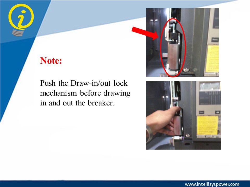
Note: Push the Draw-in/out lock mechanism before drawing in and out the breaker. www.intellisyspower.com
42
Pull-out the ACB PULLING IN AND OUT OF ACB Pull-IN the ACB GREEN ARROW DRAW-OUT THE ACB RED ARROW DRAW-IN THE ACB www.intellisyspower.com

43
MICROLOGIC TRIP UNIT 2.0A INDICATING LED’s LCD SCREEN KEYS LONG TIME DELAY LONG TIME SHORT TIME RESET BUTTON www.intellisyspower.com

Similar presentations


 4Mechanical Air Leak- Down 4Mechanical Air Leak- Up 4Electronic Drift- Up/ Down 4Load Cell Operation 4Understanding.>")
 Digital multimeter (DMM) Power Supply Signal Generator Oscilloscope.>")


