Download presentation
Presentation is loading. Please wait.

1
Report on Sigmaphi 75 kW RFQ Amplifier and Ferrite 75 kW Circulator Ralph Pasquinelli November 18, 2014

2
Of the 32 RF power slices, 8 of them had water leaks. Two from Amplifier 1 were fixed by Kermit, but it was labor intensive. Sigmaphi asked that the balance be returned to be modified in France. This took two months including US customs delay. Only amplifier SN 01 could be commissioned with a full compliment of amplifier slices. 95 F water temperature caused amplifier to trip even though it is in range of water input T. At 90 F a warning light comes on. Initially the water heat exchanger not capable of regulating the water temperature. Excess water flow also caused a trip, we changed that set point. An external fault supplied by Fermilab interlock hardware locks up the amplifier and it is not possible to reset the unit even after powering down for 30 minutes to two hours. This is requiring a field engineer from Sigmaphi to come to Fermilab for investigation. Circulators are specified to run at 95 F, but the manufacturer Ferrite did not take into account the delta T between the water input temp and that of the ferrite disc. Ferrite supplied three 75 kW circulators, the first two tested to 10 kW the third is tested for the first time at CMTF. Delivery Status of Amplifiers and Circulators

4
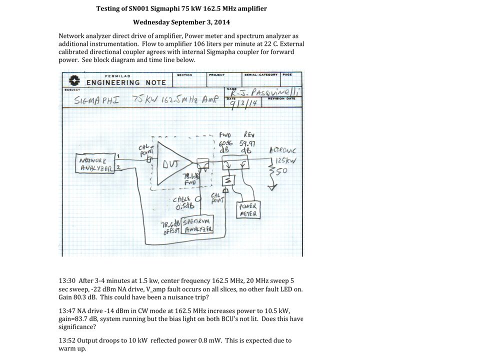
RF Block Diagram 128-600 Watt Modules Combined to make 75kW

6
Sigmaphi RFQ Amplifier Specifications

8
13:54 Display 3 shows 2.5 kW fwd and 39 w rev, other reverse power monitors indicate “no signal”. 13:57 NA drive increased to -11 dBm, output power to 23 kW ran less than one minute then tripped on V_amp fault all slices, remote fault monitor indicates internal PS fault, but no other LED indicators. 14:00 after reset and DC on command a fan fault on fifth from top right slice SN18 CAN 4 came on and faulted the amplifier, did not reset with reset button, but did reset with DC off command. 14:01 DC on causes same fan fault. 14:02 DC off resets fan fault and V_amp fault on all slices. 14:05 turning off CCU and Driver and main power switch then power back on and fan fault remains. Inspection of the spare slice shows five internal fans, four with “wind tunnel” the fifth larger fan looks to be generic chassis cooling. Without the MOD bus information, we cannot tell which of the fans has failed. The fan fault is immediate after it first tripped, so it must not be due to temperature but rather rotation? Please advise the next step. We have a spare slice that needs to be tested for water- cooling channel integrity. Are the phases of spare modules such that the spare can just be swapped into this position or is there a phase adjustment someplace in the hardware?

9
Serial # 01, 12 kW 40 kHz Sidebands60 Hz Sidebands Initially the amp would not run above this power level because our Temperature sensor would provide an external fault for a step in power.

10
Preliminary tests of Sigmaphi 75 kW 162.5 MHz RFQ amplifier September 17, 2014 The water cooling system heat exchanger not yet able to regulate water temperature, hence an observable increase in water temperature during the course of the testing. water flow at 23 gallons per minute maximum water temperature is 35 C, 95 F at which time the amp trips off. We installed a series resistor to trick the water temp circuit.

11
Green water temp F Red fwd power watts CW test at 27 KW for approximately 30 minutes. Arrow shows time synchrony. Top network analyzer magnitude and phase, bottom forward power and water temperature out. Steps in gain and power output observed. It turned out the steps were from instability of the NA output. -10 dBm drive from NA

12
Red water temp F Green fwd power watts CW test at 45 KW for approximately 30 minutes. Arrow shows time synchrony. Top network analyzer magnitude and phase, bottom forward power and water temperature out. Red arrow shows time synchrony Left bay water temp warning at 84.3F Right bay water temp warning at 85.3 F -7 dBm drive from NA

13
Network analyzer in power sweep mode.

14
SN01 output harmonics at 75 kW

15
SN01 run overnight starting at 56 kW then dropping and recovering need to check the drive signal for stability. 10-7-14 to 10-8-14 Green Fwd power Red input water T=68 F Yellow bay water T in Blue bay water T out Delta T=7C or 13F

16
Ferrite UFC3-540 SN2272 75 kW 162.5 MHz Circulator Ralph J. Pasquinelli October 9,22,23, 2014 Transfer function measurements as a function of input water temperature and power vs frequency test

17
PXIE RFQ RF installation at CMTF

18
or How to get the water Just Right

19
This report shows the performance of the circulator under matched conditions and with shorted port 2. The first series of s parameters are made with a network analyzer at low powers. The water temperature is indicated and the system was allowed to reach equilibrium at each temperature. Without a heat source other than the pump, low level measurements were limited to 91 F. The circulator looks to be tuned at 95 F as specified. For the shorted test, the short was placed at two positions 1/8 wavelength apart with similar results for each position. Two tests at 70 F and 85 F input water temp measured. When power is applied, the frequency response changes dramatically. There is a clear difference in the input and output water temperature as expected. The flow is only 4.1 GPM through the circulator. A test was performed with a pressure difference of 110 psi and only 4.8 GPM was achievable. Load test was performed with loads on ports 2 & 3. Nominal operating power is expected to be 65 kW. At powers above 60 kW the best match occurs above 162.5 MHz. The final test was varying the water temperature set point at the water skid to tune the best match to 162.5 MHz with loads on ports 2 and 3.

20
Input Water Temperature = 68.6 F

21
Input Water Temperature = 74.5 F

22
Input Water Temperature = 80.3 F

23
Input Water Temperature = 85 F

24
Input Water Temperature = 91 F water skid set to 95 F, Delta T due to radiation from pipes

25
Input Water Temperature = 70 F, short circuit on port 2, amplifier reflected power vs freq Blue 10 kW, Magenta 20 kW, Yellow 30 kW, markers indicate minimal power and freq

26
Input Water Temperature = 70 F, short circuit on port 2, amplifier reflected power vs freq Blue 40 kW, Magenta 50 kW, Yellow 60 kW, markers indicate minimal power and freq. note at these higher powers, minimum reflected is beyond the amplifier bandwidth (5 MHz)
.")
27
Input Water Temperature = 85 F, short circuit on port 2, amplifier reflected power vs freq Blue 10 kW, Magenta 20 kW, Yellow 30 kW, markers indicate minimal power and freq. Note there does not appear to be a sharp power minimum.

28
Input Water Temperature = 85 F, short circuit on port 2, amplifier reflected power vs freq Blue 30 kW, Magenta 40 kW, Yellow 50 kW, markers indicate minimal power and freq. note at these higher powers, minimum reflected is beyond the amplifier bandwidth (5 MHz) return loss only 10 dB and minimum appears higher in frequency.
 return loss only 10 dB and minimum appears higher in frequency..")
29
Input Water Temperature = 85 F, red is the difference between input and output water temp yellow is the forward power out of the amplifier. Water flow is 4.1 GPM. At 60 kW, the delta T is approximately 6 deg F. The thermal impedance between the water channels and the ferrite disc requires this lower operating water temperature.

30
Plot of running conditions for testing the circulator with loads on ports 2 & 3. Green water temp deg F with one degree resolution, red is radiated power into the room antenna in dBm, Yellow is the forward power in kW, blue is the transistor temperatures of one of the amplifier modules in deg C. Trip level is 70 C.

31
Input Water Temperature = 85 F, blue 20 kW, magenta 30 kW, yellow 40 kW amp reflected power into a 50 ohm load. Of all the measurements only at 30 kW is such a pronounce match visible. Tends to be broader at all other powers. Spikes are generated by the stepping of the signal generator.

32
Input Water Temperature = 85 F, blue 50 kW, magenta 60 kW, yellow 70 kW amp reflected power into a 50 ohm load.

33
Input Water Temperature = 85 F, yellow 60 kW, blue 70 kW, magenta 75 kW amp reflected power into a 50 ohm load. (note color scheme different from previous plots due to operator, i.e.me)
.")
34
Measurement of reflected power as a function of the set point on the water skid at 65 kW amp power 50 ohm load. Blue is 85 F, magenta is 84 F, yellow is 82.5 F and the sweet spot. This is with only one amp running and the LEBT energized. As more loads are added, the temperature at the circulators may vary and adjustments made.

35
Running at 74 kw (yellow), temperature of transistors in C (blue), radiated power dBm into room antenna (red), cooling water temperature (green). Abrupt turn off of power to see time constant, about ten minutes to stabilize transistor temp, six minutes for the water loop.

36
We have received all the leaky RF slices back from Sigmaphi. They have been leak tested and installed in the bays. All connections made up. Water temp needs to be at 83-85 F, resistors removed from amp 1 water trip circuit. The water system looks to be incapable of supplying water to both RF systems simultaneously. This needs to be remedied before the arrival of the RFQ. Ready to start the commissioning of Amp 2 and circulator 2. Sigmaphi field engineer comes to Fermilab first week of December to fix interlock issues. For PXIE operations, a Frequency control loop will be added to change the drive frequency until the RFQ is at the proper resonance before driving with the master oscillator. Current Status November 18, 2014

Similar presentations


 Transmitters>")

.>")


 Han and Nemuel Magno Group 14 ENEL 434 – Electronics 2 Assignment 2012 1.>")

