Download presentation
Presentation is loading. Please wait.

1
LECTURE 1

2
Introduction to Internal Combustion Engines.

3
INTRODUCTION ENGINE Mechanical device which converts one form of energy into other form of energy

4
INTRODUCTION =Heat engine : It can be defined as any engine that converts thermal energy to mechanical work output. Examples of heat engines include: steam engine, diesel engine, and gasoline (petrol) engine. On the basis of how thermal energy is being delivered to working fluid of the heat engine, heat engine can be classified as an internal combustion engine and external combustion engine.
 engine. On the basis of how thermal energy is being delivered to working fluid of the heat engine, heat engine can be classified as an internal combustion engine and external combustion engine.")
5
TYPES OF ENGINES In an Internal combustion engine, combustion takes place inside the engine cylinder Petrol & Diesel engine is an example of internal combustion engine, where the working fluid is a mixture of air and fuel . In an External combustion engine, combustion takes place outside the engine cylinder Steam engine is an example of external combustion engine, where the working fluid is steam.

6
TYPES OF ENGINES Internal combustion engine

7
TYPES OF ENGINES Internal combustion engine

8
TYPES OF ENGINES External combustion engine

9
TYPES OF ENGINES External combustion engine

10
TYPES OF IC ENGINES Internal combustion engines may be classified as :
Spark Ignition engines. Compression Ignition engines.

11
TYPES OF IC ENGINES Spark ignition engine (SI engine):
An engine in which the combustion process in each cycle is started by use of an external spark. Compression ignition engine (CI engine): An engine in which the combustion process starts when the air-fuel mixture self ignites due to high temperature in the combustion chamber caused by high compression.
: An engine in which the combustion process starts when the air-fuel mixture self ignites due to high temperature in the combustion chamber caused by high compression.")
12
TYPES OF IC ENGINES Spark ignition engine

13
TYPES OF IC ENGINES Compression ignition engine

14
It has four piston strokes over two revolutions for each cycle.
Spark ignition and Compression Ignition engine operate on either a four stroke cycle or a two stroke cycle. Four stroke cycle : It has four piston strokes over two revolutions for each cycle. Two stroke cycle : It has two piston strokes over one revolution for each cycle.

15
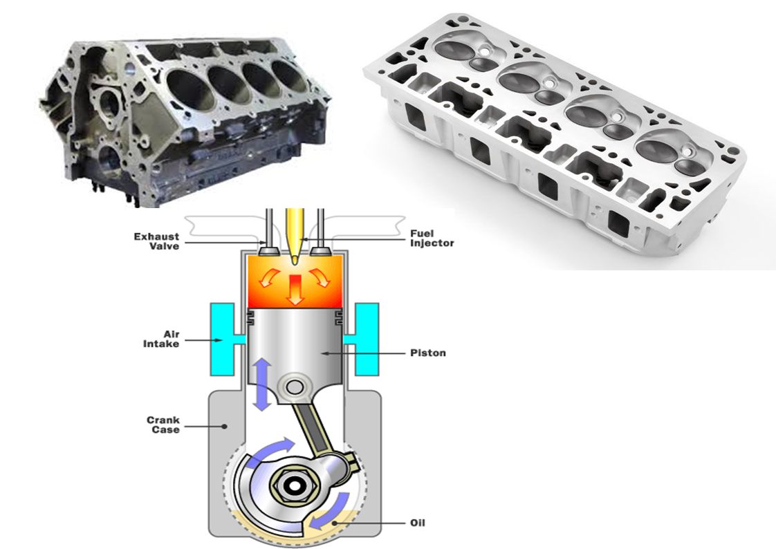
Internal combustion Engine Components

17
Internal combustion Engine Components:
I.C. Engine components shown in figure1 and figure2 are defined as follows: Block : Body of the engine containing cylinders, made of cast iron or aluminum. Cylinder : The circular cylinders in the engine block in which the pistons reciprocate back and forth. Head : The piece which closes the end of the cylinders, usually containing part of the clearance volume of the combustion chamber. Combustion chamber: The end of the cylinder between the head and the piston face where combustion occurs. The size of combustion chamber continuously changes from minimum volume when the piston is at TDC to a maximum volume when the piston at BDC.

19
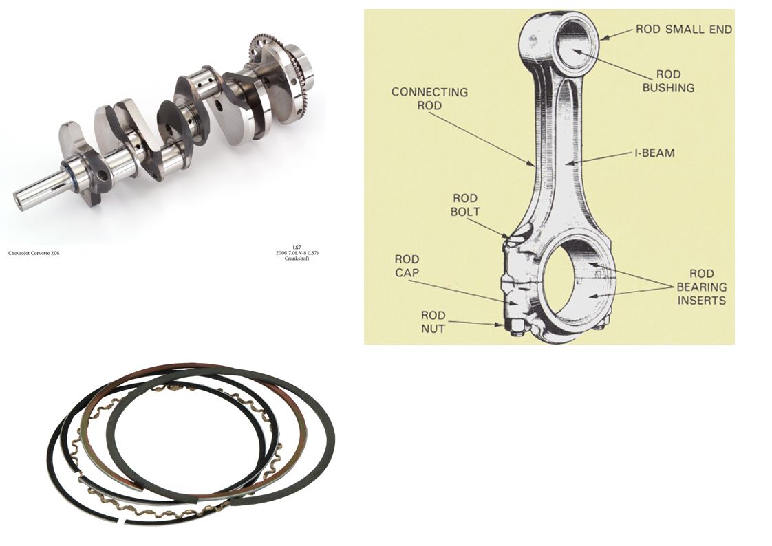
Crankshaft : Rotating shaft through which engine work output is supplied to external systems.
The crankshaft is connected to the engine block with the main bearings. It is rotated by the reciprocating pistons through the connecting rods connected to the crankshaft, offset from the axis of rotation. This offset is sometimes called crank throw or crank radius. Connecting rod : Rod connecting the piston with the rotating crankshaft, usually made of steel or alloy forging in most engines but may be aluminum in some small engines. Piston rings: Metal rings that fit into circumferential grooves around the piston and form a sliding surface against the cylinder walls.

21
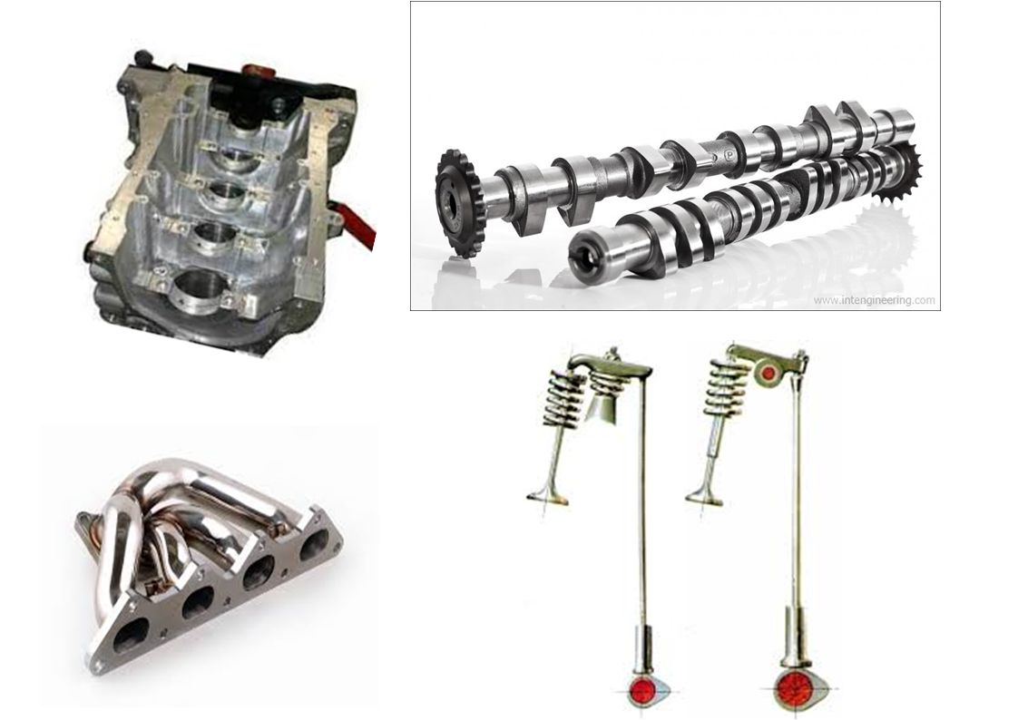
Camshaft : Rotating shaft used to push open valves at the proper time in the engine cycle, either directly or through mechanical or hydraulic linkage (push rods, rocker arms) . Push rods : The mechanical linkage between the camshaft and valves on overhead valve engines with the camshaft in the crankcase. Crankcase : Part of the engine block surrounding the crankshaft. In many engines the oil pan makes up part of the crankcase housing. Exhaust manifold : Piping system which carries exhaust gases away from the engine cylinders, usually made of cast iron .

23
Intake manifold :Piping system which delivers incoming air to the cylinders, usually made of cast metal, plastic, or composite material. In most SI engines, fuel is added to the air in the intake manifold system either by fuel injectors or with a carburetor. The individual pipe to a single cylinder is called runner. Carburetor : A device which meters the proper amount of fuel into the air flow by means of pressure differential. For many decades it was the basic fuel metering system on all automobile (and other) engines. Spark plug : Electrical device used to initiate combustion in an SI engine by creating high voltage discharge across an electrode gap.
 engines. Spark plug : Electrical device used to initiate combustion in an SI engine by creating high voltage discharge across an electrode gap.")
24
LECTURE 2

25
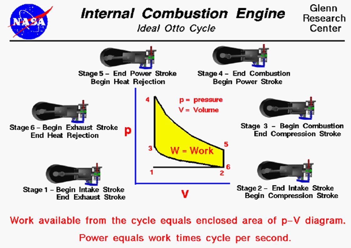
Engine Terminology : Figure 3, shows the pressure volume diagram of ideal engine cycle along with engine terminology as follows: Top Dead Center (TDC): Position of the piston when it stops at the furthest point away from the crankshaft. Top because this position is at the top of the engines (not always), and dead because the piston stops as this point. Because in some engines TDC is not at the top of the Some source call this point TOP Center (TC). When the piston is at TDC, the volume in the cylinder is a minimum called the clearance volume.
: Position of the piston when it stops at the furthest point away from the crankshaft. Top because this position is at the top of the engines (not always), and dead because the piston stops as this point. Because in some engines TDC is not at the top of the. Some source call this point TOP Center (TC). When the piston is at TDC, the volume in the cylinder is a minimum called the clearance volume.")
26
Bottom Dead Center (BDC): Position of the piston when it stops at the point closest to the crankshaft. Some sources call this Crank End Dead Center (CEDC) because it is not always at the bottom of the engine. Some source call this point Bottom Center (BC). Stroke : Distance traveled by the piston from one extreme position to the other : TDC to BDC or BDC to TDC. Bore :It is defined as cylinder diameter or piston face diameter; piston face diameter is same as cylinder diameter( minus small clearance). Swept volume/Displacement volume : Volume displaced by the piston as it travels through one stroke. Swept volume is defined as stroke times bore. Displacement can be given for one cylinder or entire engine (one cylinder times number of cylinders).
 because it is not always at the bottom of the engine. Some source call this point Bottom Center (BC). Stroke : Distance traveled by the piston from one extreme position to the other : TDC to BDC or BDC to TDC. Bore :It is defined as cylinder diameter or piston face diameter; piston face diameter is same as cylinder diameter( minus small clearance). Swept volume/Displacement volume : Volume displaced by the piston as it travels through one stroke. Swept volume is defined as stroke times bore. Displacement can be given for one cylinder or entire engine (one cylinder times number of cylinders).")
27
Clearance volume : It is the minimum volume of the cylinder available for the charge (air or air fuel mixture) when the piston reaches at its outermost point (top dead center or outer dead center) during compression stroke of the cycle. Minimum volume of combustion chamber with piston at TDC. Compression ratio : The ratio of total volume to clearance volume of the cylinder is the compression ratio of the engine. Typically compression ratio for SI engines varies form 8 to 12 and for CI engines it varies from 12 to 24

28
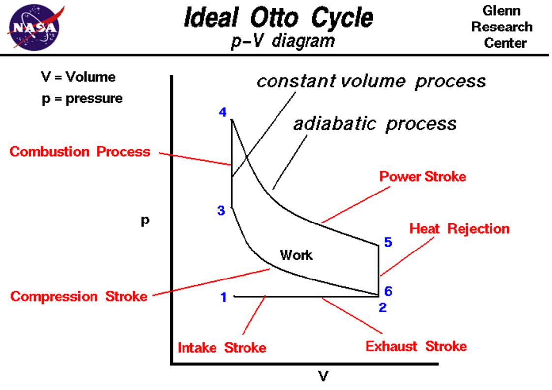
SI Engine Ideal Otto Cycle
We will be dealing with four stroke SI engine, the following figure shows the PV diagram of Ideal Otto cycle.

32
Figure4: Suction stroke

33
Four strokes of SI Engine Cycle :
Suction/Intake stroke: Intake of air fuel mixture in cylinder through intake manifold. The piston travel from TDC to BDC with the intake valve open and exhaust valve closed. This creates an increasing volume in the combustion chamber, which in turns creates a vacuum. The resulting pressure differential through the intake system from atmospheric pressure on the outside to the vacuum on the inside causes air to be pushed into the cylinder. fuel is added by fuel injectors.

34
Figure5: Compression Stroke

35
Compression stroke: When the piston reaches BDC, the intake valve closes and the piston travels back to TDC with all valves closed. This compresses air fuel mixture, raising both the pressure and temperature in the cylinder. Near the end of the compression stroke the spark plug is fired and the combustion is initiated.

36
Combustion of the air-fuel mixture occurs in a very short but finite length of time with the piston near TDC (i.e., nearly constant volume combustion). It starts near the end of the compression stroke slightly before TDC and lasts into the power stroke slightly after TDC. Combustion changes the composition of the gas mixture to that of exhaust products and increases the temperature in the cylinder to a high value. This in turn increases the pressure in the cylinder to a high value.

37
Figure6: Combustion followed by Expansion stroke.

38
Expansion stroke/Power stroke : With all valves closed the high pressure created by the combustion process pushes the piston away from the TDC. This is the stroke which produces work output of the engine cycle. As the piston travels from TDC to BDC, cylinder volume is increased, causing pressure and temperature to drop.

39
Figure7: Exhaust blowdown followed by Exhaust stroke

40
Exhaust stroke: By the time piston reaches BDC, exhaust blowdown is complete, but the cylinder is still full of exhaust gases at approximately atmospheric pressure. With the exhaust valve remaining open, the piston travels from BDC to TDC in the exhaust stroke. This pushes most of the remaining exhaust gases out of the cylinder into the exhaust system at about atmospheric pressure, leaving only that trapped in the clearance volume when the piston reaches TDC.

41
Near the end of the exhaust stroke before TDC, the intake valve starts to open, so that it is fully open by TDC when the new intake stroke starts the next cycle. Near TDC the exhaust valve starts to close and finally is fully closed sometime after TDC. This period when both the intake valve and exhaust valve are open is called valve overlap.

42
Compression Ignition Engine :
We will deal with Compression Ignition engine. The ideal diesel cycle PV diagram is shown in following figure 8.

43
Figure8: Ideal diesel cycle P-V Diagram.

44
Figure9: Four strokes of ideal Diesel cycle.

45
Figure10:Suction stroke

46
Figure11: Compression stroke

47
Four strokes of CI Engine Cycle :
Intake/Suction Stroke : The same as the intake stroke in an SI engine with one major difference : no fuel is added to the incoming air, Compression Stroke : The same as in an SI engine except that only air is compressed and compression is to higher pressures and temperature, Late in the compression stroke fuel is injected directly into the combustion chamber, where it mixes with very hot air. This causes the fuel to evaporate and self ignite, causing combustion to start. Combustion is fully developed by TDC and continues at about constant pressure until fuel injection is complete and the piston has started towards BDC,

48
Figure12:Fuel injection and combustion followed by Expansion stroke .

49
Figure13: Exhaust stroke followed by exhaust blowdown.

50
THANK YOU

Similar presentations


 Patel Vidhi A.>")


 Optional Introduction to Naval Engineering.>")

. TEAM WORK 1 - احمد جمال منصور عبدالعزيز سكشن 1 2 - احمد السيد احمد حسن ابوالغيط سكشن 1 3 - احمد السيد محمد.>")