Download presentation
Presentation is loading. Please wait.

1
ERT 321 – Process Control & Dynamics Feedforward & Ratio Control Ms Anis Atikah Ahmad anisatikah@unimap.edu.my

2
OUTLINE Introduction to Feedforward Control Ratio Control Other Control Strategies

3
One of the simplest process control schemes. A feedback loop measures a process variable and sends the measurement to a controller for comparison to set point. If the process variable is not at set point, control action is taken to return the process variable to set point. Advantage: corrective action occurs as soon the CV deviates from setpoint. Disadvantage: not provide predictive control action to compensate for the effects of known or measurable disturbance Intro: Feedback Control Parameter being measured: Controlled Variable ( level of the water in the boiler)
.")
4
Basic concept: to measure important disturbance variables and take corrective action before they upset the process. Feedforward Control Parameter being measured: disturbance variable (steam flow rate)
.")
5
Feedforward Control (cont.) Feedforward control is normally used in combination with feedback controller. Controller with summing functions are used in these combined systems to sum up the input from both the feedforward loop and the feedback loop, and send a unified signal to the final control element. Feedforward plus feedback controller

6
Ratio control is used to ensure that two or more flows are kept at the same ratio even if the flows are changing. Ratio Control MV DV

7
Ratio Control (cont.) WaterAcid 2 part of water 1 part of acid FT FF FIC
 WaterAcid 2 part of water 1 part of acid FT FF FIC")
8
Ratio Control (cont.) Typical applications of ratio control include: 1. Setting the relative amounts of components in blending operations 2. Maintaining a stoichiometric ratio of reactants to a reactor 3. Keeping a specified reflux ratio for a distillation column 4. Holding the fuel-air ratio to a furnace at the optimum value

9
Method I Disadvantage: divider element makes the process gain vary in a non-linear fashion, where:

10
Method II Desired ratio Transmitter span for DV & MV

11
Example 15.1 A ratio control scheme is to be used to maintain a stoichiometric ratio of H 2 and N 2 as the feed to an ammonia synthesis reactor. Individual flow controllers will be used for both H 2 and N 2 streams. Based on the following information: The spans of the flow trasmitters are 30L/min for H 2 and 15 L/min for N 2. The control valves have pneumatic actuators. Each required current-to-pressure (I/P) transducer has a gain of 0.75 psi/mA. The ratio station is an electronic instrument with 4-20 mA input and output signals. (i)Draw a schematic diagram for the ratio control scheme (ii)Specify the appropriate gain for the ratio station, K R
 transducer has a gain of 0.75 psi/mA. The ratio station is an electronic instrument with 4-20 mA input and output signals. (i)Draw a schematic diagram for the ratio control scheme (ii)Specify the appropriate gain for the ratio station, K R.")
12
Example 15.1-Sol (a) Ratio control schematic diagram 3H 2 + N 2 ⇌ 2NH 3 In order to introduce a feed mixture in stoichiometric proportion, the ratio of the molar flow rates (H 2 /N 2 ) should be 3:1. Assume ratio of molar flowrates = ratio of volumetric flow rates;

13
Example 15.1-Sol (b) A ppropriate gain for the ratio station, K R The stoichiometric equation for ammonia synthesis reaction is: 3H 2 + N 2 ⇌ 2NH 3 From stoichiometric equation, it follows that the desired ratio is, R d =u/d =1/3 Substituting into gives;
 A ppropriate gain for the ratio station, K R The stoichiometric equation for ammonia synthesis reaction is: 3H 2 + N 2 ⇌ 2NH 3 From stoichiometric equation, it follows that the desired ratio is, R d =u/d =1/3 Substituting into gives;")
14
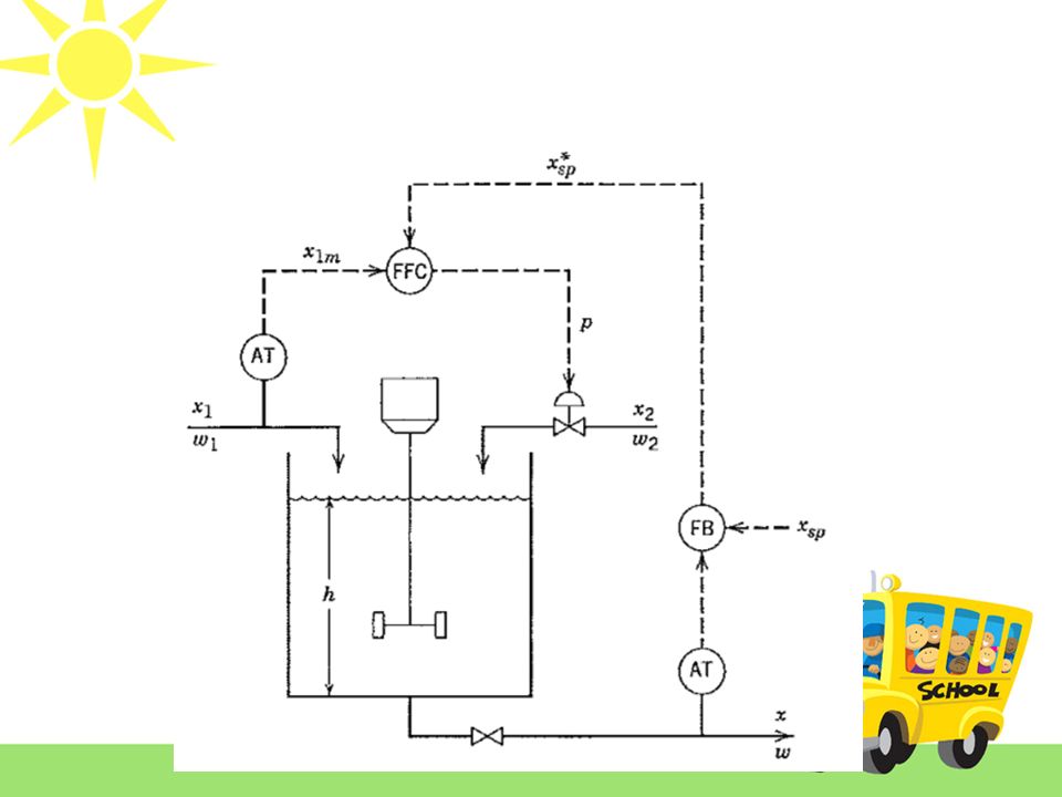
Block diagram of Feedforward- Feedback control system Figure 15-11: A block diagram of feedforward-feedback control system

15
The closed-loop transfer function for disturbance changes can be derived as follows: Ideally, we want a perfect control, where the CV remains exactly at the set point with any changes in DV. If the set point is constant, Y sp (s) =0, Y(s) =0, This condition can be satisfied by setting the numerator of Eq15-21= 0. Thus: Feedforward-Feedback control system Eq 15-21
 =0, Y(s) =0, This condition can be satisfied by setting the numerator of Eq15-21= 0. Thus: Feedforward-Feedback control system Eq")
16
Stability Considerations Consider the closed-loop system in Figure 15-11:

17
Stability Considerations From the closed-loop transfer function in Eq 15-21, the characteristic equation is: -Since G f does not appear in the characteristic equation, the feedforward controller has no effect on the stability of feedback control system. This allows the feedback & feedforward controllers to be tuned individually. Eq 15-21

18
Feedback-Feedforward Configuration Typical configuration: Feedforwrad control in this strategy does not affect the stability of feedback control loop

19
Feedback-Feedforward Configuration Alternative configuration: Feedback controller output serve as the setpoint for the feedforward controller. -> The feedforward control can affect the stability of feedback control system.

21
Cascade Control uses the output of the primary controller (master) to manipulate the set point of the secondary controller (slave) as if it were the final control element. The output of the master controller being used to adjust the set point of the slave controller. Cascade control

22
Cascade control (cont.)
")
23
TK-100 (pH adjustment tank) TK-101 (acid feed tank) The diagram shows pH adjustment; part of waste water treatment process. The process shall maintained at pH 6. When the process liquid states below pH 6, CV-102 will be opened to dosing NaOH to the tank TK-100. When the process liquid states above pH 6, CV-101 will be operated to dosing HCl. TK-102 (base feed tank) CV-101 CV-102 pHT 1 pHIC Split Range Control Output of a controller is split to two or more control valves.
 CV-101 CV-102 pHT 1 pHIC Split Range Control Output of a controller is split to two or more control valves..")
24
V-100 FT Process variable need to be controlled = Pressure FC Y PT PIC Identify type of control loop used below. Exercise…

Similar presentations


>")


