Download presentation
Presentation is loading. Please wait.

1
In this unit we are learning about the physics of electricity and electronics. This includes circuits, Ohm’s law, resistance, electrical energy and power.

2
Electric Circuits Vocabulary Potential Difference/Voltage/EMF CircuitOhm’s Law CurrentVoltmeter ResistanceAmmeter PowerSeries Circuit Direct Current (DC)Parallel Circuit Alternating Current (AC) Compound (Complex) Circuit
Parallel Circuit Alternating Current (AC) Compound (Complex) Circuit")
3
What is electricity?

4
Key words: electrons, conductors, insulators, charge, current By the end of this lesson you will be able to: State that electrons are free to move in a conductor Describe the electrical current in terms of movement of charges around a circuit Distinguish between conductors and insulators and give examples of each.

5
The atom An atom is a fundamental unit of matter made up of protons (with a positive charge) neutrons (neutral – no charge) electrons (with a negative charge)
 neutrons (neutral – no charge) electrons (with a negative charge)")
6
What is electricity? Everything is made of atoms which contain POSITIVE particles called PROTONS and NEGATIVE particles called ELECTRONS. Proton (+) Neutron Electron (-)
 Neutron Electron (-).")
7
An atom will usually have the same number of positives and negatives This makes the atom NEUTRAL. Proton (+) Neutron Electron (-)
 Neutron Electron (-).")
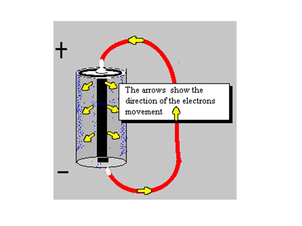
8
Electrical Charge Electric charge is given the symbol Q Electrons are the charge carriers that flow in an electrical circuit – from the negative to positive terminals.

9
Electrical Charge Charge is measured in Coulombs which is given the symbol C

10
Electrical Charge The charge on a proton is 1.6 x 10 -19 C which is the same size as the charge on an electron.

11
What is electricity? Electrons have a negative charge (Q) measured in coulombs (C). Electrons move round a circuit from negative to positive (remember like charges repel, opposites attract) giving rise to an electric current.
 giving rise to an electric current..")
12
What is an insulator? Name some conductors and insulators What makes them effective conductors / insulators? What is a conductor?

13
Conductors & Insulators What makes something a good conductor? Good conductors allow electrons to move through them easily. Insulators do not allow electrons to move easily.

14
What is electricity? So electricity is… movement of charge round a circuit. We call this electric current.

16
Potential Difference =Voltage=EMF In a battery, a series of chemical reactions occur in which electrons are transferred from one terminal to another. There is a potential difference (voltage) between these poles. The maximum potential difference a power source can have is called the electromotive force or (EMF), . The term isn't actually a force, simply the amount of energy per charge (J/C or V)
 between these poles. The maximum potential difference a power source can have is called the electromotive force or (EMF), . The term isn t actually a force, simply the amount of energy per charge (J/C or V).")
17
A Basic Circuit All electric circuits have three main parts 1. A source of energy 2. A closed path 3. A device which uses the energy If ANY part of the circuit is open the device will not work!

18
Electricity can be symbolic of Fluids Circuits are very similar to water flowing through a pipe A pump basically works on TWO IMPORTANT PRINCIPLES concerning its flow There is a PRESSURE DIFFERENCE where the flow begins and ends A certain AMOUNT of flow passes each SECOND. A circuit basically works on TWO IMPORTANT PRINCIPLES There is a "POTENTIAL DIFFERENCE aka VOLTAGE" from where the charge begins to where it ends The AMOUNT of CHARGE that flows PER SECOND is called CURRENT.

19
Charge, Current & Time Electric current is given the symbol I Electric current is the movement of negative charges (electrons) in a circuit
 in a circuit")
20
Charge, Current & Time Current is the amount of charge flowing per second and is given the unit Amps (A)
")
21
Charge, Current & Time If current is charge flowing per second then time in seconds (s) Current in Amps (A) Charge transferred in coulombs (C) so a current of 1 A is 1 C of charge transferred in 1 s.
 Current in Amps (A) Charge transferred in coulombs (C) so a current of 1 A is 1 C of charge transferred in 1 s.")
22
Charge, Current & Time This can be rearranged as or

23
Current Current is defined as the rate at which charge flows through a surface. The current is in the same direction as the flow of positive charge (though sometimes it is considered in a different way…more on this later!) Note: The “I” stands for intensity
 Note: The I stands for intensity.")
24
There are 2 types of Current DC = Direct Current - current flows in one direction Example: Battery AC = Alternating Current- current reverses direction many times per second. This suggests that AC devices turn OFF and ON. Example: Wall outlet (progress energy)
.")
25
Key words: series, parallel, current, ammeter, voltmeter, battery, resistor, variable resistor, fuse, switch, lamp, voltage By the end of this lesson you will be able to: Draw circuit diagrams to show the correct positions of an ammeter in a series or parallel circuit. Draw and identify the circuit symbols for an ammeter, voltmeter, battery, resistor, variable resistor, fuse, switch and lamp. State that in a series circuit, the current is the same at all positions. State that in a parallel circuit, the sum of the current in the branches adds up to the current drawn from the supply.

26
Name that component Voltmeter Lamp Fuse Switch Cell Battery Variable resistor Resistor Ammeter

27
Ways to Wire Circuits There are 2 basic ways to wire a circuit. Keep in mind that a resistor could be ANYTHING ( bulb, toaster, ceramic material…etc) Series – One after another Parallel – between a set of junctions and parallel to each other
 Series – One after another Parallel – between a set of junctions and parallel to each other.")
28
Schematic Symbols Before you begin to understand circuits you need to be able to draw what they look like using a set of standard symbols understood anywhere in the world For the battery symbol, the LONG line is considered to be the POSITIVE terminal and the SHORT line, NEGATIVE. The VOLTMETER and AMMETER are special devices you place IN or AROUND the circuit to measure the VOLTAGE and CURRENT.

29
The Voltmeter and Ammeter The voltmeter and ammeter cannot be just placed anywhere in the circuit. They must be used according to their DEFINITION. Since a voltmeter measures voltage or POTENTIAL DIFFERENCE it must be placed ACROSS the device you want to measure. That way you can measure the CHANGE on either side of the device. Voltmeter is drawn ACROSS the resistor Since the ammeter measures the current or FLOW it must be placed in such a way as the charges go THROUGH the device. Current goes THROUGH the ammeter

30
Simple Circuit When you are drawing a circuit it may be a wise thing to start by drawing the battery first, then follow along the loop (closed) starting with positive and drawing what you see.
 starting with positive and drawing what you see.")
31
When a battery is in a circuit… The electrical energy is carried by the electrons that move round the circuit. It is converted into others forms of energy.

32
The amount of electrical energy the electrons have at any point in a circuit is known as their “potential”. As they move the electrons transfer energy into other forms. This means at any two points the electron has different amounts of energy.

33
Electrons start with (for example) 6J of energy. They have “potential”. As they pass through the bulb, some of the energy is converted to light. Electrons which have passed through the bulb have less energy. Or less “potential”. There is a “potential” difference in the circuit

34
What has “potential difference” got to do with voltage? It is the same thing! The potential difference (p.d.), or voltage, of a battery is a measure of the electrical energy given to one coulomb of charge passing through the battery.
, or voltage, of a battery is a measure of the electrical energy given to one coulomb of charge passing through the battery..")
35
Potential Difference or Voltage (V) A 9 V battery will give how much energy to each coulomb of charge passing through the battery? 9 J

36
Potential Difference or Voltage (V) A 1.5 V battery will give how much energy to each coulomb of charge passing through the battery? 1.5 J

37
Potential Difference or Voltage (V) A battery with a p.d. of 6V will give how much energy to each coulomb of charge passing through the battery? 6 J

38
Voltage or p.d. Voltage (or p.d.) is measured in volts and is given the symbol V
 is measured in volts and is given the symbol V")
39
How can we measure voltage? Voltage (or p.d.) can be measured using a voltmeter. An ammeter is connected in the circuit but a voltmeter must be connected across the component. V

40
You can’t measure voltage… in a circuit through a circuit through a component flowing

41
Key words: resistance, series, parallel, ohms, ohmmeter By the end of this lesson you will be able to: State the relationships between total resistance and individual resistances in series and parallel circuits Carry out calculations involving the relationships between resistors in series and in parallel

42
The symbol for a resistor is Resistors

43
Relationship between current and voltage in a resistor I / Amps p.d. / Volts Straight line through the origin tells us that current is directly proportional to voltage The ratio V/I is constant and is equal to resistance in the circuit.

44
Relationship between current and voltage in a resistor

45
Ohm’s Law

46
“The voltage (potential difference, emf) is directly related to the current, when the resistance is constant” Since R= V/I, the resistance is the SLOPE of a V vs. I graph R= resistance = slope

47
Resistance Resistance (R) – is defined as the restriction of electron flow. It is due to interactions that occur at the atomic scale. For example, as electron move through a conductor they are attracted to the protons on the nucleus of the conductor itself. This attraction doesn’t stop the electrons, just slow them down a bit and cause the system to waste energy. The unit for resistance is the OHM,

48
Resistors A lamp What do you expect to happen to the current if you increase the value of the resistor in the circuit shown? cell resistor Demonstration

49
Calculate For a voltage of 12V, calculate the current for a resistant of (i)1 Ω (ii)2 Ω (iii)4 Ω (iv)24 Ω (v)1 k Ω
1 Ω (ii)2 Ω (iii)4 Ω (iv)24 Ω (v)1 k Ω")
50
Measuring Resistance or we can measure it directly using an ohmmeter Ω Demonstration & experiment

51
Series and Parallel Circuits Voltage, Current and Resistance VsVs I3I3 I2I2 I1I1 R3R3 +- R2R2 R1R1 V1V1 V2V2 V3V3 What type of circuit is this?

52
VsVs I3I3 I2I2 I1I1 R3R3 +- R2R2 R1R1 V1V1 V2V2 V3V3 One electrical path from negative to positive therefore series.

53
Series Circuit In in series circuit, the resistors are wired one after another. Since they are all part of the SAME LOOP they each experience the SAME AMOUNT of current. In figure, however, you see that they all exist BETWEEN the terminals of the battery, meaning they SHARE the potential (voltage).
..")
54
Series Circuit As the current goes through the circuit, the charges must USE ENERGY to get through the resistor. So each individual resistor will get its own individual potential voltage). We call this VOLTAGE DROP. Note: They may use the terms “effective” or “equivalent” to mean TOTAL!
. We call this VOLTAGE DROP. Note: They may use the terms effective or equivalent to mean TOTAL!.")
55
Example A series circuit is shown to the left. a) What is the total resistance? b) What is the total current? c) What is the current across EACH resistor? d) What is the voltage drop across each resistor?( Apply Ohm's law to each resistor separately) R(series) = 1 + 2 + 3 = 6 V=IR 12=I(6) I = 2A They EACH get 2 amps! V 1 2 VV 3 =(2)(3)= 6VV 2 =(2)(2)= 4V Notice that the individual VOLTAGE DROPS add up to the TOTAL!!
 What is the total current. c) What is the current across EACH resistor. d) What is the voltage drop across each resistor ( Apply Ohm s law to each resistor separately) R(series) = = 6 V=IR 12=I(6) I = 2A They EACH get 2 amps. V 1 2 VV 3 =(2)(3)= 6VV 2 =(2)(2)= 4V Notice that the individual VOLTAGE DROPS add up to the TOTAL!!.")
56
VsVs I3I3 I2I2 I1I1 R3R3 +- R2R2 R1R1 V1V1 V2V2 V3V3 What is the relationship between the three currents? The current is the same at each point.

57
VsVs I3I3 I2I2 I1I1 R3R3 +- R2R2 R1R1 V1V1 V2V2 V3V3 What is the relationship between the four voltages? They add to equal the supply voltage.

58
Disadvantages of Series Circuits? When one component fails the whole circuit fails. The current is the same at all points and the voltage is divided between the bulbs. The more bulbs added the dimmer each one is.

59
VsVs I3I3 I2I2 I1I1 R3R3 +- R2R2 R1R1 V1V1 V2V2 V3V3 How do you find total resistance in series? Add each resistance together.

60
What type of circuit is this? ITIT ITIT VsVs I3I3 I2I2 I1I1 R3R3 +- R2R2 R1R1 V1V1 V2V2 V3V3

61
More than one electrical path – components connected on different branches therefore parallel. ITIT ITIT VsVs I3I3 I2I2 I1I1 R3R3 +- R2R2 R1R1 V1V1 V2V2 V3V3

62
Parallel Circuit In a parallel circuit, we have multiple loops. So the current splits up among the loops with the individual loop currents adding to the total current It is important to understand that parallel circuits will all have some position where the current splits and comes back together. We call these JUNCTIONS. The current going IN to a junction will always equal the current going OUT of a junction. Junctions

63
Parallel Circuit Notice that the JUNCTIONS both touch the POSTIVE and NEGATIVE terminals of the battery. That means you have the SAME potential difference down EACH individual branch of the parallel circuit. This means that the individual voltages drops are equal. This junction touches the POSITIVE terminal This junction touches the NEGATIVE terminal VV

64
Example To the left is an example of a parallel circuit. a) What is the total resistance? b) What is the total current? c) What is the voltage across EACH resistor? d) What is the current drop across each resistor? (Apply Ohm's law to each resistor separately) 2.20 3.64 A 8 V each! 1.6 A1.14 A0.90 A Notice that the individual currents ADD to the total.
 What is the total resistance. b) What is the total current. c) What is the voltage across EACH resistor. d) What is the current drop across each resistor. (Apply Ohm s law to each resistor separately) 2.20 3.64 A 8 V each. 1.6 A1.14 A0.90 A Notice that the individual currents ADD to the total..")
65
What is the relationship between the four currents? The four currents add to give the total current. ITIT ITIT VsVs I3I3 I2I2 I1I1 R3R3 +- R2R2 R1R1 V1V1 V2V2 V3V3

66
What is the relationship between the four voltages? Each voltage is equal to the supply voltage. ITIT ITIT VsVs I3I3 I2I2 I1I1 R3R3 +- R2R2 R1R1 V1V1 V2V2 V3V3

67
ITIT ITIT VsVs I3I3 I2I2 I1I1 R3R3 +- R2R2 R1R1 V1V1 V2V2 V3V3 The resistance in parallel?

68
If more resistors are connected in parallel the total resistance will always decrease This is because there are more branches through which the electricity can flow.

69
Advantages of the Parallel Circuit? When one bulb fails the rest of the circuit continues to work. The more components, the lower the resistance. The total current drawn increases. Voltage in each branch is the same as the supply voltage therefore bulbs in parallel will each be as bright as a single bulb.What have you learned today?

70
Name each component. What type of circuit is this? V V

71
The supply voltage is 6V. What is voltage V 1 ? V 2 ? V1V1 V2V2 10 Ω

72
The supply voltage is 10V. What is voltage V 1 ? V 2 ? V1V1 V2V2 10 Ω

73
The supply voltage is 6V. What is voltage V 1 ? V 2 ? V1V1 V2V2 5Ω5Ω 10 Ω

74
Compound (Complex) Circuits Many times you will have series and parallel in the SAME circuit. Solve this type of circuit from the inside out. WHAT IS THE TOTAL RESISTANCE?

75
Compound (Complex) Circuits Suppose the potential difference (voltage) is equal to 120V. What is the total current? 1.06 A What is the VOLTAGE DROP across the 80 resistor? 84.8 V

76
Compound (Complex) Circuits What is the VOLTAGE DROP across the 100 and 50 resistor? 35.2 V Each! What is the current across the 100 and 50 resistor? 0.352 A 0.704 A Add to 1.06A

77
Key words: electrical energy, power, voltage, current, resistance By the end of this lesson you will be able to: State that the electrical energy transformed each second = VI Carry out calculations using P=IV and E=Pt Explain the equivalence between VI, I 2 R and V 2 /R. Carry out calculations involving the relationships between power, current, voltage and resistance.

78
POWER It is interesting to see how certain electrical variables can be used to get POWER. Let’s take Voltage and Current for example.

79
Other useful power formulas These formulas can also be used! They are simply derivations of the POWER formula with different versions of Ohm's law substituted in.

80
Power For example, an appliance with a power rating of 250 W converts 250 Joules of electrical energy into another form each second.

81
Power How can this be written as a formula? Power in Watts (W) Energy in Joules (J) time in seconds (s) Demonstration / experiment
 Energy in Joules (J) time in seconds (s) Demonstration / experiment.")
82
Power & Energy Example If an electric fire uses 1.8 MJ of energy in a time of 10 minutes, calculate the power output of the fire.

83
Power & Energy Example P = ? E = 1.8 MJ = 1.8x10 6 J t=10 minutes = 600 s

84
Formula?

85
The formula which links voltage, power and current: P = VI

Similar presentations


>")


 of the bulb through the filament inside.>")

