Download presentation
Presentation is loading. Please wait.

1
IB Physics 12 Mr. Jean November 21 st, 2013

2
The plan: Video clip of the day Practice question for series circuit Understanding basic electric measurement tools Parallel circuits

3
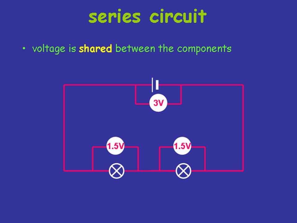
Series Circuit As the current goes through the circuit, the charges must USE ENERGY to get through the resistor. So each individual resistor will get its own individual potential voltage). We call this VOLTAGE DROP. Note: They may use the terms effective or equivalent to mean TOTAL!
. We call this VOLTAGE DROP. Note: They may use the terms effective or equivalent to mean TOTAL!.")
4
Example A series circuit is shown to the left. a)What is the total resistance? b)What is the total current? c)What is the current across EACH resistor? d)What is the voltage drop across each resistor?( Apply Ohm's law to each resistor separately)
What is the total current. c)What is the current across EACH resistor. d)What is the voltage drop across each resistor ( Apply Ohm s law to each resistor separately).")
5
Example A series circuit is shown to the left. a)What is the total resistance? b)What is the total current? c)What is the current across EACH resistor? d)What is the voltage drop across each resistor?( Apply Ohm's law to each resistor separately) R(series) = 1 + 2 + 3 = 6 V=IR 12=I(6) I = 2A They EACH get 2 amps! V 1 2 VV 3 =(2)(3)= 6VV 2 =(2)(2)= 4V Notice that the individual VOLTAGE DROPS add up to the TOTAL!!
What is the total current. c)What is the current across EACH resistor. d)What is the voltage drop across each resistor ( Apply Ohm s law to each resistor separately) R(series) = = 6 V=IR 12=I(6) I = 2A They EACH get 2 amps. V 1 2 VV 3 =(2)(3)= 6VV 2 =(2)(2)= 4V Notice that the individual VOLTAGE DROPS add up to the TOTAL!!.")
6
Parallel Circuit In a parallel circuit, we have multiple loops. So the current splits up among the loops with the individual loop currents adding to the total current It is important to understand that parallel circuits will all have some position where the current splits and comes back together. We call these JUNCTIONS. The current going IN to a junction will always equal the current going OUT of a junction. Junctions

7
Circuits in Parallel A circuit in parallel means that each component has the same potential difference. In this example all 4 lamps have the full battery voltage across them; however the current is divided between the 4 lamps.

8
Parallel Circuit:

9
Parallel Circuits: V s = V 1 = V 2 = … = V n Skiing example: The ski hill represents the battery and the runs represent the resistors. Each skier has the same gravitational potential difference, likewise each individual load in a parallel circuit must have the same total potential difference. This is a Mr. Jean original drawing if you couldnt tell....

10
Current in parallel circuits I s = summation of current for circuit. I s = I 1 + I 2 + I 3 + …. + I n Therefore:

11
Resistors in Parallel For resistors in parallel the inverse of the equivalent resistance is the sum of the inverses of the individual resistances.

12
Example: There is a 12 volt battery which is connect to three resistors 3.0Ω, 12.0Ω, and 6.0Ω in parallel. –1) Draw the circuit. –2) Find the equivalent resistance for the situation. –3) Find the total current leaving the battery. –4) Find the current through the 12.0 Ω resistor.
 Draw the circuit. –2) Find the equivalent resistance for the situation. –3) Find the total current leaving the battery. –4) Find the current through the 12.0 Ω resistor..")
13
1) The circuit:
 The circuit:")
14
2) R eq
 R eq")
15
3) Current leaving the battery:
 Current leaving the battery:")
16
4) Find the current through 12Ω
 Find the current through 12Ω")
17
Parallel Circuit Notice that the JUNCTIONS both touch the POSTIVE and NEGATIVE terminals of the battery. That means you have the SAME potential difference down EACH individual branch of the parallel circuit. This means that the individual voltages drops are equal. This junction touches the POSITIVE terminal This junction touches the NEGATIVE terminal V

18
Important Assumption: For the next 9 slides assume that the LAMPS are all identical to each other. –Ie: Same resistance, same wattage, same intensity, same make, etc……

19
Measuring current Electric current is measured in amps (A) using an ammeter connected in series in the circuit. A

20
The Ammeter The ammeter cannot be just placed anywhere in the circuit. They must be used according to their DEFINITION. Since the ammeter measures the current or FLOW it must be placed in such a way as the charges go THROUGH the device. Current goes THROUGH the ammeter

23
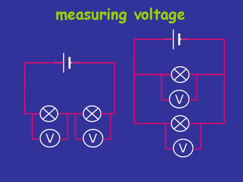
Measuring voltage The electrical push which the cell gives to the current is called the voltage. It is measured in volts (V) on a voltmeter V
 on a voltmeter V.")
24
The Voltmeter The voltmeter cannot be just placed anywhere in the circuit. They must be used according to their DEFINITION. Since a voltmeter measures voltage or POTENTIAL DIFFERENCE it must be placed ACROSS the device you want to measure. That way you can measure the CHANGE on either side of the device. Voltmeter is drawn ACROSS the resistor

26
Different cells produce different voltages. The bigger the voltage supplied by the cell, the bigger the current. Measuring voltage Unlike an ammeter, a voltmeter is connected across the components Scientist usually use the term Potential Difference (pd) when they talk about voltage.
 when they talk about voltage..")
30
To do: Continue to work on Quest assignment Continue to read about circuits and their application Review notes, videos, online tutorials & additional material attached to website

Similar presentations


 I= Current (Amperes) (amps) V= Voltage (Volts) R= Resistance (ohms)>")

>")


