Download presentation
Presentation is loading. Please wait.

1
November 4, 2013 Topic: Electric Circuit Objectives:
1. Describe the elements of an electric circuit. 2. Discuss the current and voltage characteristics of series and parallel circuits.

2
Will This Work?

3
Will This Work?

4
Will This Work?

5
A Basic Circuit All electric circuits have three main parts
1. A source of energy 2. A closed path 3. A device which uses the energy If ANY part of the circuit is open the device will not work!

6
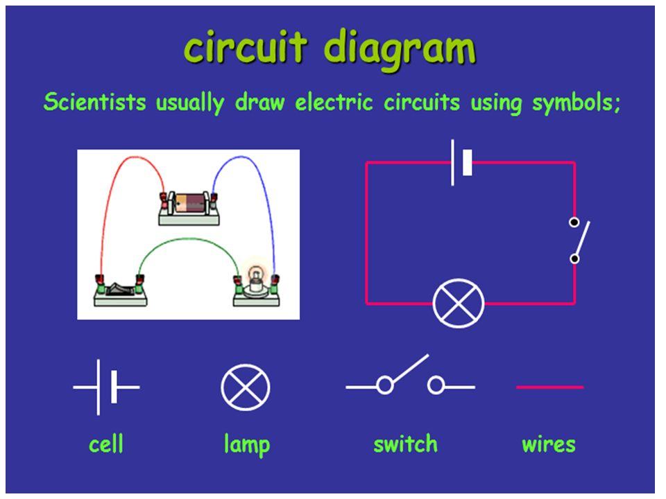
Schematic Symbols Before you begin to understand circuits you need to be able to draw what they look like using a set of standard symbols understood anywhere in the world For the battery symbol, the LONG line is considered to be the POSITIVE terminal and the SHORT line , NEGATIVE. The VOLTMETER and AMMETER are special devices you place IN or AROUND the circuit to measure the VOLTAGE and CURRENT.

8
The Voltmeter and Ammeter
The voltmeter and ammeter cannot be just placed anywhere in the circuit. They must be used according to their DEFINITION. Current goes THROUGH the ammeter Since a voltmeter measures voltage or POTENTIAL DIFFERENCE it must be placed ACROSS the device you want to measure. That way you can measure the CHANGE on either side of the device. Voltmeter is drawn ACROSS the resistor Since the ammeter measures the current or FLOW it must be placed in such a way as the charges go THROUGH the device.

9
Series Circuit In in series circuit, the resistors are wired one after another. Since they are all part of the SAME LOOP they each experience the SAME AMOUNT of current. In figure, however, you see that they all exist BETWEEN the terminals of the battery, meaning they SHARE the potential (voltage).
.")
10
Series Circuit As the current goes through the circuit, the charges must USE ENERGY to get through the resistor. So each individual resistor will get its own individual potential voltage). We call this VOLTAGE DROP. Note: They may use the terms “effective” or “equivalent” to mean TOTAL!
. We call this VOLTAGE DROP. Note: They may use the terms effective or equivalent to mean TOTAL!")
11
Example A series circuit is shown to the left.
What is the total resistance? What is the total current? What is the current across EACH resistor? What is the voltage drop across each resistor?( Apply Ohm's law to each resistor separately) R(series) = = 6W DV=IR =I(6) I = 2A They EACH get 2 amps! V1W=(2)(1)= 2 V V3W=(2)(3)= 6V V2W=(2)(2)= 4V Notice that the individual VOLTAGE DROPS add up to the TOTAL!!
 R(series) = = 6W. DV=IR 12=I(6) I = 2A. They EACH get 2 amps! V1W=(2)(1)= 2 V V3W=(2)(3)= 6V V2W=(2)(2)= 4V. Notice that the individual VOLTAGE DROPS add up to the TOTAL!!")
12
Parallel Circuit In a parallel circuit, we have multiple loops. So the current splits up among the loops with the individual loop currents adding to the total current It is important to understand that parallel circuits will all have some position where the current splits and comes back together. We call these JUNCTIONS. The current going IN to a junction will always equal the current going OUT of a junction. Junctions

13
Parallel Circuit Notice that the JUNCTIONS both touch the POSTIVE and NEGATIVE terminals of the battery. That means you have the SAME potential difference down EACH individual branch of the parallel circuit. This means that the individual voltages drops are equal. DV This junction touches the POSITIVE terminal This junction touches the NEGATIVE terminal

14
Example To the left is an example of a parallel circuit. a) What is the total resistance? b) What is the total current? c) What is the voltage across EACH resistor? d) What is the current drop across each resistor? (Apply Ohm's law to each resistor separately) 2.20 W 3.64 A 8 V each! Notice that the individual currents ADD to the total. 1.6 A 1.14 A 0.90 A
 What is the voltage across EACH resistor d) What is the current drop across each resistor (Apply Ohm s law to each resistor separately) 2.20 W A. 8 V each! Notice that the individual currents ADD to the total. 1.6 A A A.")
15
Total Power The total power of the circuit equals the sum of the powers of the individual loads regardless of the kind of the circuit (series, parallel, or series-parallel combination) 𝑃 𝑇 = 𝑃 1 + 𝑃 2 + 𝑃 3 Total power can also be calculated using: 𝑃 𝑇 = 𝐼 𝑇 2 𝑅 𝑒𝑞 𝑃 𝑇 = 𝑉 𝑇 2 𝑅 𝑒𝑞 𝑃 𝑇 = 𝐼 𝑇 𝑉 𝑇
 𝑃 𝑇 = 𝑃 1 + 𝑃 2 + 𝑃 3 Total power can also be calculated using: 𝑃 𝑇 = 𝐼 𝑇 2 𝑅 𝑒𝑞 𝑃 𝑇 = 𝑉 𝑇 2 𝑅 𝑒𝑞 𝑃 𝑇 = 𝐼 𝑇 𝑉 𝑇")
16
Fuse and Circuit breakers

17
Fuse is a type of low resistance resistor that acts as a sacrificial device to provide overcurrent protection, of either the load or source circuit. made of a metal wire or strip that melts when too much current flows, which interrupts the circuit in which it is connected It is connected in series with the load.

18
Circuit breaker a manually or automatically operated electrical switch designed to protect an electrical circuit from damage caused by overload or short circuit. detects a fault condition and interrupt current flow. unlike a fuse, which operates once and then must be replaced, a circuit breaker can be reset (either manually or automatically) to resume normal operation.
 to resume normal operation.")
Similar presentations


 Sources: Battery, 120 V plug,>")


 Current (Amps) Resistance (Ohms or Ω)>")
>")
