Download presentation
Presentation is loading. Please wait.

1
KINEMATICS OF MACHINE GEARS
PREPARED BY, JIGNESH VANPARIYA ( ) DARSHN INSTITUTE OF ENGG. & TECHNOLOGY
 DARSHN INSTITUTE OF ENGG. & TECHNOLOGY.")
2
CONTENT Law of Gearing Length of Path of Contact
Length of Arc of Contact Difference in Involute Gear Minimum Number of Teeth on Pinion to Avoid Interference

3
Statement : LAW OF GEARING :
The law of gearing states the condition which must be fulfilled by the gear tooth profiles to maintain a constant velocity ratio between two gears. The condition is that “ For constant velocity ratio of the two gears, the common normal at the point of contact the two mating teeth must pass through the pitch point.

4
Proof : Let the two teeth come in contact at point Q, and the wheel rotates in the direction as shown in fig. Let , TT = common tangent MN= common normal

5
Now, from the centers O₁ and O₂, draw O₁M and O₂N perpendicular to MN.
A little consideration will show that the point Q moves in the direction QC, when considered as a point on the wheel 1, and in the direction QD, when considered as a point on the wheel 2. Let v ₁ and v ₂ be the velocities of the point Q on the wheels 1 and 2. If the velocities along the common normal MN must be equal.

7
From above, we see that the angular velocity ratio is inversely proportional to the ratio of the two surfaces at the point of contact Q intersects the line of centers at point P which divides the centre distance inversely as the ratio of angular velocities. Therefore in order to have constant angular velocity ratio for all positions of the wheels, the point P must be the fixed point for the two wheels. In other words, the common normal at the point of contact between a pair of teeth must always pass through the pitch point. It is known as law of gearing.

8
LENGTH OF PATH OF CONTACT :
Consider a pinion driving the wheel as shown in fig. When the pinion rotates in clockwise direction, the contact between a pair of involute teeth begins at K and end at L.

9
MN is the common normal at the point of contact and the common tangent to the base circles.
The point K is the intersection of the addendum circle of the wheel and the common tangent. The point L is the addendum circle of pinion and common tangent. Thus, the length of path of contact is KL which is the sum of the part of the path of contact KP and PL. The part of the path of contact KP is known as path of approach and the part of the path of contact PL is known as path of recess.

12
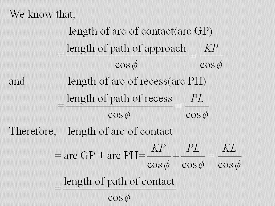
LENGTH OF ARC OF CONTACT :
The arc of contact is the path traced by a point on the pitch circle from the beginning of to the end of engagement of a given pair of teeth. The arc of contact is GPH, where GP is arc of approach and PH is arc of recess.

14
INTERFERENCE IN INVOLUTE GEAR :
Let, O₁ = centre of wheel O₂ = centre of pinion R = radius of wheel r = radius of pinion MN= common tangent KL = length of path of contact

15
Now, if the radius of addendum of pinion is increased to O₁N, the point of contact L will move from L to N. When this radius is further increased, the point of contact L will be on the inside of base circle of wheel and not on the involute profile of tooth on the wheel. The tip of tooth on the pinion will then undercut the tooth on the wheel at the root and remove part of the involute profile of the tooth on the wheel. This effect is known as interference, and occur when the teeth are being cut.

16
The phenomenon when the tip of tooth undercuts the root on its mating gear is known as interference.
Similarly, if the radius of the addendum of wheel increased beyond O₂M, then the tip of tooth on the wheel will cause interference with the tooth on pinion. Here, The points M and N are called interference point. The limiting value of the radius of the addendum of the pinion is O₁N and of the wheel O₂M.

17
MINIMUM No. OF TEETH ON THE PINION TO AVOID INTERFERENCE :
In order to avoid interference, the addendum circle for the two mating gears must cut the common tangent to the base circles between the point of tangency. The limiting condition reaches, when the addendum of pinion and wheel pass though point M and N.

Similar presentations


>")
 Change torque, speed Why we need gears Example: engine of a containership –Optimum operating speed of the engine about 400 RPM.>")
 driven.>")
 Cam-Followers and Point-Follower 3.4.1, 3.4.2 September 27, 2013 Radu Serban University of Wisconsin-Madison.>")
