Download presentation
Presentation is loading. Please wait.

1
Built-up Compression Members

2
For large loads and for efficient use of material, built-up columns (also called as combined columns or open-web columns) are often used. They are generally made up of two or more individual sections such as angles, channels, or I-sections and properly connected along their length by lacing or battening so that they act together as a single unit.

4
Struts with batten plates Battened struts
According to the type of connection between the chords, built-up members may be classified as follows: Laced members Struts with batten plates Battened struts Members with perforated cover plates

5
Struts with batten plates

6
The effect of shear in built-up-column sets apart the design of these members from that of other columns. The effect of shear on deflections is much greater

7
Lateral loads from wind, earthquake, gravity, or other causes
The shear in column may be due to the following: Lateral loads from wind, earthquake, gravity, or other causes The slope of column with respect to the line of thrust due both to un-intentional initial curvature and the increased curvature during buckling The end eccentricity of the load due to either end connections or fabrication imperfections.

8
LACINGS 8

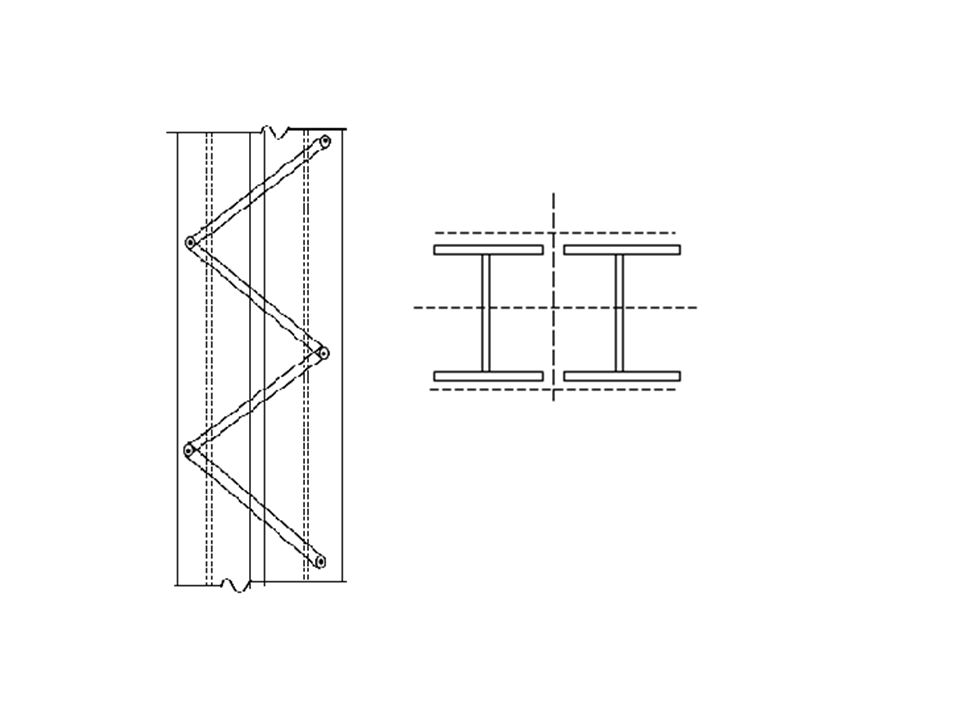
9
Lacing is generally a flat which connects two components of column section obliquely at a convenient inclination. The lacing design includes selection of this inclination, flat width and thickness, connection at end for specified design forces. Lacings 9

10
Rules Specified in the Indian Code

11
In most of the codes, latticed members are designed and proportioned according to detailed empirical rules, most of which are related to local buckling requirements. In the Indian code (IS 800 : 2007), the following rules are given. 11

12
The radius of gyration of the combined column about the axis perpendicular to the plane of lacing should be greater than the radius of gyration about the axis parallel to the plane of lacing ry > rz

13
Lacing system should be of uniform inclination throughout the length of the column.
Single and double laced systems should not be provided on the opposite sides of the same member. Similarly lacings and battens should not be provided on opposite sides of the same member.

14
Single laced system on opposite sides of the main component shall be in the same direction viewed from either side so that one is the shadow of the other. The lacing shall be designed to resist a total transverse shear Vt at any point in the member, equal to 2.5% of the axial force in the member; and this shear shall be divided among the lacing systems in parallel planes.

15
The slenderness ratio of lacing shall not exceed 145.
The lacings in addition should be designed to resist any shear due to bending moment or lateral load on the member. The slenderness ratio of lacing shall not exceed 145. The effective length shall be taken as the length between inner end bolts/rivets of the bar for single lacings and 0.7 times the length for double lacings effectively connected at intersections.

16
For welded bars, the effective length is taken as 0
For welded bars, the effective length is taken as 0.7 times the distance between the inner ends of the welds connecting the single bars to the members. The minimum width of the lacing bar shall not be less than approximately three times the diameter of the connecting bolt/rivet; the thickness shall not be less than 1/40th of the effective length for single lacing and 1/60th for double lacing.

17
The spacing of lacing bars shall be such that the maximum slenderness ratio of the components of the main member between two consecutive lacing connections is not greater than 50 or 0.7 times the most unfavourable slenderness ratio of the combined column.

18
When welded lacing bars overlap the main members, the amount of lap should be not less than four times the thickness of the bar and the welding is to be provided along each side of the bar for the full length of lap. Where lacing bars are fitted between main members, they should be connected by fillet welds on each side or by full penetration butt weld

19
Where lacing bars are not lapped to form the connection to the components of members, they shall be so connected that there is no appreciable interruption in the triangulated system. Plates shall be provided at the ends of laced compression members and shall be designed as battens. Flats, angles (normally adopted in practice), channels, or tubes may be used as lacings.
, channels, or tubes may be used as lacings.")
20
Lacing bars, whether in double or single shear shall be inclined at an angle of 40o to 70o to the axis of the built-up member. The effective slenderness ratio (KL/r)e of the laced column shall be taken as 1.05 times (KL/r)0, where (KL/r)0 , is the maximum actual slenderness ratio of the column, to account for shear deformation effects.
e of the laced column shall be taken as 1.05 times (KL/r)0, where (KL/r)0 , is the maximum actual slenderness ratio of the column, to account for shear deformation effects.")
21
Battens The rules for the design of battens shall be the same as for lacings except for the following conditions (see Fig.)
")
22
The number of battens shall be such that the member is divided into not less than three bays.
The thickness of batten plates shall not be less than 1/50th of the distance between the innermost connecting transverse bolts/rivets or welds.

23
Battens shall be designed to resist simultaneously
Longitudinal shear Vb = Vt Lo / ns Moment M = Vt Lo / 2n where Vt is the transverse shear force as defined in the case of lacings, Lo is the distance between centre-to-centre of battens, longitudinally, n is the number of parallel planes of battens, and s is the minimum transverse distance between the centroids of the bold/rivet group/welding connecting the batten to the main member.

24
When plates are used for battens, the effective depth between the end bolts/rivets or welds shall not be less than twice the width of one member in the plane of battens; nor less than three quarters of the perpendicular distance between centroids of the main members for end battens.

25
When connected to main members by welds, the length of the weld connecting each end of the batten shall not be less than half the depth of the plate; at least one third of its length should be placed at each end of the edge; in addition the weld shall be returned along the other two edges for a length not less than the minimum lap (i.e. , not less than four times the thickness of the plate.) The length of the weld and depth of batten shall be measured along the longitudinal axis of the main member.
 The length of the weld and depth of batten shall be measured along the longitudinal axis of the main member..")
26
The requirement of size and thickness does not apply when other rolled sections are used for battens with their legs or flanges perpendicular to the main member. The effective slenderness ratio of battened column shall be taken as 1.10 times (KL/r)o, where (KL/r)o is the maximum actual slenderness ratio of the column, to account for shear deformation effects.
o, where (KL/r)o is the maximum actual slenderness ratio of the column, to account for shear deformation effects.")
27
Battened compression members, not complying with the preceding rules or those subjected to eccentricity of loading, applied moments, and lateral forces in the plane of the battens, shall be designed according to exact theory of elastic stability or empirically but verified by test results. It should be noted that in Western countries such as USA and UK, due to the prohibitive labour and fabrication costs and the availability of larger rolled steel sections, built-up columns are seldom used nowadays.

28
THANK YOU

Similar presentations


 Compression element, Axial or bending2.6.1(p8) Compression element, Axial or bending Axial.>")
 Spring 2008>")


 CE 408 ( 2 – 3 – 3 ) Semester 062>")


