Download presentation
Presentation is loading. Please wait.

1
OPERATIONS MANUAL

2
OPERATIONS MANUAL PART-A GENERAL / BASIC 8. OPERATING PROCEDURES
8.3. FLIGHT PROCEDURES REV16

3
8. OPERATING PROCEDURES 8.3. FLIGHT PROCEDURES
VFR/IFR POLICY All flights have to be conducted under IFR rules, for all flights an ATC flight plan must be filled. In the vicinity of the airport an approach may be conducted by visual maneuvering (circling) under IFR rules if this type of approach is cleared by the ATC and if weather conditions permit it (see chapter Aerodrome operating minima*). If visual reference is lost, the circling approach must be aborted. An aircraft should not descend in IMC below the sector safe altitude (MSA) as shown on the instrument approach chart until it is established in the approved approach or holding procedure. LOOKOUT When weather conditions permit, it is absolutely essential that flight crew maintain vigilance(uyanık) so as to see and avoid other aeroplane during all phases of a flight and in any case while operating in VMC. Particularly critical airspaces are: The vicinity of aeroplane and their approach and departure environments High density terminal areas and Airspaces where VFR flights are not subject to air traffic control service ( Class E,F and G airspaces.) When operating in airspaces deemed critical as above in appropriate weather conditions, activities through which attention is diverted from outside to within the cockpit like paper work, map reading, EICAS(Engine indicating and crew alerting system)- handling or FMS insertions, shall be reduced as far as possible. *Note: As a general rule the aerodrome operating minima are the minima indicated on the Jeppesen Approach charts.
 under IFR rules if this type of approach is cleared by the ATC and if weather conditions permit it (see chapter Aerodrome operating minima*). If visual reference is lost, the circling approach must be aborted. An aircraft should not descend in IMC below the sector safe altitude (MSA) as shown on the instrument approach chart until it is established in the approved approach or holding procedure LOOKOUT. When weather conditions permit, it is absolutely essential that flight crew maintain vigilance(uyanık) so as to see and avoid other aeroplane during all phases of a flight and in any case while operating in VMC. Particularly critical airspaces are: The vicinity of aeroplane and their approach and departure environments. High density terminal areas and. Airspaces where VFR flights are not subject to air traffic control service ( Class E,F and G airspaces.) When operating in airspaces deemed critical as above in appropriate weather conditions, activities through which attention is diverted from outside to within the cockpit like paper work, map reading, EICAS(Engine indicating and crew alerting system)- handling or FMS insertions, shall be reduced as far as possible. *Note: As a general rule the aerodrome operating minima are the minima indicated on the Jeppesen Approach charts.")
4
8. OPERATING PROCEDURES 8.3. FLIGHT PROCEDURES
VFR/IFR POLICY LOOKOUT … According to the established rules of operation within Class E, F and G airspaces, ATS generally has only incomplete or no information regarding the disposition of VFR flights therein and can provide collision hazard information to IFR flights only as far as practicable, i.e. depending on the availability of the information and the momentary workload. It is therefore the direct responsibility of the Commander to avoid collision with VFR traffic when operating in those airspaces in VMC. Flight crews shall, when receiving traffic information, sharpen their look-out accordingly and shall not abate and relax thereafter, assuming that no other traffic exists. Particularly when operating in VMC and below FL 100 the crew should refrain(kaçınmak) from all conversation which is not essential for the flight. This includes for example: • Private conversation • Use of company frequency • All other conversation which deplete the redundancy of one or more crewmembers. The Commander may deviate from the above recommendation if necessary for flight operations, i.e. after go-around to confer with the station concerned via company frequency.
 from all conversation which is not essential for the flight. This includes for example: • Private conversation • Use of company frequency • All other conversation which deplete the redundancy of one or more crewmembers. The Commander may deviate from the above recommendation if necessary for flight operations, i.e. after go-around to confer with the station concerned via company frequency.")
5
8.3.1.2. DESCENT BELOW MINIMUM SAFE EN-ROUTE ALTITUDE/MINIMUM
Safe Grid Altitude Descent below "the minimum safe en-route altitude / minimum safe grid altitude" to the minimum sector altitude may be made when approaching the navigation aid from which an approach-to-land will be conducted, provided the aeroplane’s position can be accurately established as being within 25 NM from the navigation aid upon which the minimum sector altitude is based by: • The use of a radio navigational aid or • Positive radar control. NOTE: The foregoing does not apply when the flight is cleared to descent during radar vectoring or to conduct a visual approach. DESCENT BELOW MINIMUM SECTOR ALTITUDE When conducting radar vectored instrument approaches, clearance to descent below the minimum sector altitude may be accepted, provided the Commander is able to monitor the aeroplane’s position using the available radio navigational aids. In certain instances the minimum sector altitude for a given sector may be higher than the minimum safe en-route altitude established for a particular route segment between fixes or for a holding area within that sector. In such cases descent below the minimum sector altitude down to the minimum safe en-route altitude is permitted, provided the flight is conducted along the respective route or within the holding area. Definition: Minimum sector altitude is the lowest altitude which will provide a minimum clearance of 300 m (1.000ft.) above all objects located in an area contained within a sector of a circle of 46 km (25 NM) radius centered on a radio aid to navigation. NOTE: The foregoing does not apply when the flight is cleared to descent during radar vectoring or to conduct a visual approach
 above all objects located in an area contained within a sector of a circle of 46 km (25 NM) radius centered on a radio aid to navigation. NOTE: The foregoing does not apply when the flight is cleared to descent during radar vectoring or to conduct a visual approach.")
6
8. OPERATING PROCEDURES 8.3. FLIGHT PROCEDURES
NAVIGATION PROCEDURES GENERAL An aeroplane shall not be operated unless the navigation equipment required or otherwise installed is approved and installed in accordance with the applicable requirements including operational and airworthiness requirements and the minimum standards applicable. A failure of a single unit required for operation shall not result in the inability to operate safety on the route to be flown. Detailed information about the required operational status of equipment is provided in the MEL. Navigation and communication equipment is installed to enable or to assist flight crews to perform and/or to optimize flights with regard to safety, comfort and economy. The pilots are responsible for the correct use of the equipment in accordance with the limitations laid down in the AOM/FCOM. Continuous monitoring of the equipment and its performance is mandatory during any use of it. Special attention shall be paid to the engagement status of systems used in order to avoid late recognition of mode or configuration changes which could result in abnormal situations (e.g., unscheduled disengagement). Degradation of on-board equipment must be taken into consideration for any in-flight planning/re-planning with regard to destination and alternate weather, and for fuel planning for en-route conditions. Any downgrading of ground facilities shall be assessed with regard to possible increased landing minima at destination and/or alternate airports.
. Degradation of on-board equipment must be taken into consideration for any in-flight planning/re-planning with regard to destination and alternate weather, and for fuel planning for en-route conditions. Any downgrading of ground facilities shall be assessed with regard to possible increased landing minima at destination and/or alternate airports.")
7
8. OPERATING PROCEDURES 8.3. FLIGHT PROCEDURES
NAVIGATION PROCEDURES GENERAL … Whether navigating on manually-tuned navigation aids, on the navigation system or on radar vectors, cross-checks of the primary aids are essential. The sole use of the airborne navigation systems carried on the aeroplane is not adequate for all phases of flight and should be supplemented by specific independent checks using those equipment not directly required for navigation. Flight plans activated in the navigation system shall be checked by both Pilots waypoint by waypoint against the flight plan. Where a FMS is also suitable and authorized for pre-flight planning (when an Operational Flight Plan is not available) and for in-flight re-planning, all available means (e.g., Route Facility Charts) shall be used to crosscheck the corresponding data. Not with standing the overall responsibility of the commander for precise navigation and proper use and handling of navigation systems, the Pilot Flying (PF) is responsible for the selection of the navigation aids and of the required navigation system configuration. Intermediate approach altitude, unless the system is certified for use in the approach according to the AOM/FCOM. If these conditions are not met, the whole descent and approach procedure shall be performed by using conventional radio-navigation.
 and for in-flight re-planning, all available means (e.g., Route Facility Charts) shall be used to crosscheck the corresponding data. Not with standing the overall responsibility of the commander for precise navigation and proper use and handling of navigation systems, the Pilot Flying (PF) is responsible for the selection of the navigation aids and of the required navigation system configuration. Intermediate approach altitude, unless the system is certified for use in the approach according to the AOM/FCOM. If these conditions are not met, the whole descent and approach procedure shall be performed by using conventional radio-navigation.")
8
8. OPERATING PROCEDURES 8.3. FLIGHT PROCEDURES
NAVIGATION PROCEDURES GENERAL … Safe terrain clearance is dependent on navigation accuracy for take-off and climb. If the departure procedures are stored in the navigation database, the onboard navigation system must be in the update mode and the system-computed positions shall be checked continuously against displayed navigation aids. If these conditions cannot be met, take-off and climb shall be performed according to conventional radio-navigation. If the arrival procedures for descent and approach are stored in the navigation database the on-board navigation system shall be in the update mode and the system-computer positions shall be checked continuously ageist displayed navigation aids. The use is restricted down to MOCA(Obstruction Clearance) /MORA(Off-Route (10nm))/MSA. Navigation aids shall be selected with respect to coverage and geometry. Adequate selection shall be ascertained for cross checks. Distance information for cross checks shall be used only if a DME is co/located with a VOR which coincides with a waypoint. DMEs co-located to ILS or approach localizers normally indicate zero DME at touch down and therefore are not suitable for navigational purposes other than the final approach - if not otherwise specified. Locators in TMAs normally provide reliable guidance within 25 NM only.
 /MORA(Off-Route (10nm))/MSA. Navigation aids shall be selected with respect to coverage and geometry. Adequate selection shall be ascertained for cross checks. Distance information for cross checks shall be used only if a DME is co/located with a VOR which coincides with a waypoint. DMEs co-located to ILS or approach localizers normally indicate zero DME at touch down and therefore are not suitable for navigational purposes other than the final approach - if not otherwise specified. Locators in TMAs normally provide reliable guidance within 25 NM only.")
9
8. OPERATING PROCEDURES 8.3. FLIGHT PROCEDURES
NAVIGATION PROCEDURES GENERAL … ILS facilities of all categories are known to produce false beams outside their coverage sectors due to radiation aberrations. Such beams are subject to being captured without a warning flag. In order to ensure proper localizer beam capture, the ILS mode shall not be armed until the vicinity of the beam has been ascertained and checked by independent means like navigation aids and the capture shall be monitored by the same means. A DME distance check at glide slope intercept shall be performed whenever possible. An altitude check shall be performed at the OM position or its equivalent. ILS localizer beam width and range available for guidance is normally of 3˚ on either side of the centerline, and 25 NM respectively. Within 30˚ on either side of this sector, coverage is provided normally to the extent that a full-scale deflection to the correct side is available. ILS glide path azimuth coverage sector normally 8˚ on either side of the centerline and extends normally to at least 10 NM. The elevation available for guidance ranges normally from at least 2˚ above to 1.5˚ below the nominal glide path, below which full-scale fly-up deflection is available.

10
8. OPERATING PROCEDURES 8.3. FLIGHT PROCEDURES
NAVIGATION PROCEDURES GENERAL *NAVIGATION AND APPROACH AIDS SHALL NOT BE USED: - whenever positive identification is not possible. - whenever reports or other information (e.g., NOTAMS) indicate that a system might be unreliable or inadequate for en-route navigation or approach. Published minima apply to the unrestricted availability of approach aids. *MINIMUM TECHNICAL SPECIFICATIONS FOR NAVIGATION CHARTS: The charts issued by Jeppesen are the only navigation charts that are allowed to be used in Onur Air flights. Before flight; the cockpit crew shall check they are updated.
 indicate that a system might be unreliable or inadequate for en-route navigation or approach. Published minima apply to the unrestricted availability of approach aids. *MINIMUM TECHNICAL SPECIFICATIONS FOR NAVIGATION CHARTS: The charts issued by Jeppesen are the only navigation charts that are allowed to be used in Onur Air flights. Before flight; the cockpit crew shall check they are updated.")
11
8. OPERATING PROCEDURES 8.3. FLIGHT PROCEDURES
NAVIGATION PROCEDURES MINIMUM NAVIGATION PERFORMANCE SPECIFICATION (MNPS) INTRODUCTION MNPS is a set of standards which require aircraft to have a minimum navigation performance capability in order to operate in MNPS designated airspace. MNPS AIRSPACE MNPS airspace (MNPSA) as it applies to the North Atlantic has been designated between FL275 and FL420, between 27 degrees north and the North Pole, bounded in the east by eastern boundaries of CTA(Control Areas) SANTA MARİA Oceanic, SHANWİCK Oceanic and REYKJAVİK; in the west by the eastern boundaries of CTA REYKJAVİK, GANDER Oceanic and NEW YORK Oceanic. And Canadian MNPS covers Arctic Control Area, Northern Control Area and portion of Southern Control Area, between FL 330 and FL 410.
 INTRODUCTION MNPS is a set of standards which require aircraft to have a minimum navigation performance capability in order to operate in MNPS designated airspace. MNPS AIRSPACE MNPS airspace (MNPSA) as it applies to the North Atlantic has been designated between FL275 and FL420, between 27 degrees north and the North Pole, bounded in the east by eastern boundaries of CTA(Control Areas) SANTA MARİA Oceanic, SHANWİCK Oceanic and REYKJAVİK; in the west by the eastern boundaries of CTA REYKJAVİK, GANDER Oceanic and NEW YORK Oceanic. And Canadian MNPS covers Arctic Control Area, Northern Control Area and portion of Southern Control Area, between FL 330 and FL 410.")
12
MNPS EQUIPMENT The minimum navigation equipment requirements are: Lateral navigation: Not less than two fully serviceable Long Range Navigation Systems (LRNS). A LNRS may be: - Inertial Navigation System (INS) - Global Navigation Satellite System (Global Positioning System - GPS) - Navigation system using the inputs from one or more Inertial Reference Systems (IRS) Each LRNS must be capable of providing a continuous indication to the flight crew of the aircraft position relative to track Longitudinal navigation: Longitudinal separation minimum are expressed in clock minutes. Devices intended to be used to indicate waypoint passing time must be accurate and is synchronized to an acceptable UTC time signal before commencing flight in MNPSA. Operations at RVSM level : The Minimum Aircraft System Performance Specification (MASPS) for Reduced Vertical Separation Minimum (RVSM) flight operations are: - Two fully serviceable independent primary altitude measurement systems - One automatic altitude-control system - One altitude-alerting device At least the two primary altimeters indications must at all times agree within ± 200ft. A functioning Mode C SSR(Secondary surveillance radar) transponder is also required for flight through radar controlled RVSM transition airspace.
 - Global Navigation Satellite System (Global Positioning System - GPS) - Navigation system using the inputs from one or more Inertial Reference Systems (IRS) Each LRNS must be capable of providing a continuous indication to the flight crew of the aircraft position relative to track Longitudinal navigation: Longitudinal separation minimum are expressed in clock minutes. Devices intended to be used to indicate waypoint passing time must be accurate and is synchronized to an acceptable UTC time signal before commencing flight in MNPSA. Operations at RVSM level : The Minimum Aircraft System Performance Specification (MASPS) for Reduced Vertical Separation Minimum (RVSM) flight operations are: - Two fully serviceable independent primary altitude measurement systems - One automatic altitude-control system - One altitude-alerting device At least the two primary altimeters indications must at all times agree within ± 200ft. A functioning Mode C SSR(Secondary surveillance radar) transponder is also required for flight through radar controlled RVSM transition airspace.")
13
MNPS APPROVAL: For operations within the MNPS Airspace (MNPSA), the operator must have obtained the approval of the operator's authority. Such approval encompasses all aspects of the expected navigation performance accuracy of the aircraft, including the navigation equipment carried, installation and maintenance procedure and crew navigation procedures and training. MNPSA SEPARATION Within the MNPSA separation standards are based upon 60 NM lateral separation, 10 minutes longitudinal separation and standard FL assignments for vertical separation but Oceanic Air Traffic Control may assign them disregarding the semicircular rule in and outside the organized track system during pick hours as follow: -during westbound flow FL 330 is delegated to Shanwick Oceanic for westbound flights: from 1130 to 1800 UTC available westbound flight levels are FL310, 330, 350, during eastbound flow FL350 is delegate to Gander Oceanic for eastbound flight: from 0100 to 0800 UTC available eastbound flight levels are FL310, 330, 360, 370. A 1000 ft. vertical separation minimum (RVSM) has been introduced between FL330 and FL370. This RVSM is expected to be introduced from FL290 to FL410. In order to maintain longitudinal separation Mach Number technique is applied with the required March number issued with the oceanic ATC clearance. It is mandatory that the assigned Mach number is strictly adhered to and any change due to turbulence etc, must be immediately communicated to ATC. After leaving oceanic airspace assigned Mach number must be maintained in domestic controlled airspace to the final position contained in the oceanic clearance unless the appropriate ATC unit authorizes a change. ETA's within the MNPS area and/or the ETA for the Oceanic Control Area entry point should be monitored and if there is a change greater than three minutes ATC should be advised. Request for step-climbs may be cleared by ATC whenever possible. Pilots should maintain their last assigned Mach number during step-climbs in MNPSA. If not possible ATC should be advice at the time of the request.
 has been introduced between FL330 and FL370. This RVSM is expected to be introduced from FL290 to FL410. In order to maintain longitudinal separation Mach Number technique is applied with the required March number issued with the oceanic ATC clearance. It is mandatory that the assigned Mach number is strictly adhered to and any change due to turbulence etc, must be immediately communicated to ATC. After leaving oceanic airspace assigned Mach number must be maintained in domestic controlled airspace to the final position contained in the oceanic clearance unless the appropriate ATC unit authorizes a change. ETA s within the MNPS area and/or the ETA for the Oceanic Control Area entry point should be monitored and if there is a change greater than three minutes ATC should be advised. Request for step-climbs may be cleared by ATC whenever possible. Pilots should maintain their last assigned Mach number during step-climbs in MNPSA. If not possible ATC should be advice at the time of the request.")
14
8. OPERATING PROCEDURES 8.3. FLIGHT PROCEDURES
POLAR NAVIGATION ONUR AIR aircraft don't have the polar navigation capabilities. The FMGS of A320 aircraft have no polar navigation capability and its use is generally limited to the latitudes 72˚ 30'N and 60˚S PERFORMANCE BASED NAVIGATION (PBN) DEFINITIONS PBN: Area navigation based on performance requirements for aircraft operating along an ATS route, on an instrument approach procedure or in a designated airspace. Performance requirements are expressed in navigation specifications in terms of accuracy, integrity, continuity and functionality needed for the proposed operation in the context of a particular airspace concept. Accuracy : The navigation performance of aircraft approved for RNAV operations requires a track keeping accuracy equal to or better than +/- 5 NM for %95 of the flight time. This value includes signal source error, airborne receiver error, display system error and flight technical error. This navigation performance assumes the necessary coverage provided by satellite or ground based navigation aids is available for the intended route to be flown.
 DEFINITIONS PBN: Area navigation based on performance requirements for aircraft operating along an ATS route, on an instrument approach procedure or in a designated airspace. Performance requirements are expressed in navigation specifications in terms of accuracy, integrity, continuity and functionality needed for the proposed operation in the context of a particular airspace concept. Accuracy : The navigation performance of aircraft approved for RNAV operations requires a track keeping accuracy equal to or better than +/- 5 NM for %95 of the flight time. This value includes signal source error, airborne receiver error, display system error and flight technical error. This navigation performance assumes the necessary coverage provided by satellite or ground based navigation aids is available for the intended route to be flown.")
15
DEFINITIONS (continued) RNAV: A navigation system which permits aircraft operation on any desired flight path within the coverage of station-referenced navigation aids or within the limits of the capability of selfcontained aids, or a combination of these. An RNAV system may be included as part of a flight management system (FMS). RNAV specification is based on area navigation that does not include the requirement for on-board performance monitoring and alerting. ONUR AIR is approved by DGCA to conduct RNAV1, RNAV5 and RNAV10 performance based navigation (PBN) operations. RNP: An area navigation system which supports on-board performance monitoring and alerting. Area Navigation Equipment: Any combination of equipment used to provide RNAV guidance. ATS Route: A specified route designed for channelling the follow of traffic as necessary for the provision of air traffic services. Cross Track Deviation: The perpendicular deviation that the aircraft is to the left or right of the desired track. Continuity of Function: The capability of the total system to perform its function. En-Route Operations: Operation conducted on published ATS routes, direct point-to-point operations between defined waypoints or along great circle routes. Figure of Merit: A system-generated indication of the quality of the actual navigation performance of the aircraft. Integrity: The ability of a system to provide timely warnings to users when the system should not be used for navigation. Sensor: A unit capable of providing information for use by the RNAV or Flight Management System (FMS) equipment.
 RNAV: A navigation system which permits aircraft operation on any desired flight path within the coverage of station-referenced navigation aids or within the limits of the capability of selfcontained aids, or a combination of these. An RNAV system may be included as part of a flight management system (FMS). RNAV specification is based on area navigation that does not include the requirement for on-board performance monitoring and alerting. ONUR AIR is approved by DGCA to conduct RNAV1, RNAV5 and RNAV10 performance based navigation (PBN) operations. RNP: An area navigation system which supports on-board performance monitoring and alerting. Area Navigation Equipment: Any combination of equipment used to provide RNAV guidance. ATS Route: A specified route designed for channelling the follow of traffic as necessary for the provision of air traffic services. Cross Track Deviation: The perpendicular deviation that the aircraft is to the left or right of the desired track. Continuity of Function: The capability of the total system to perform its function. En-Route Operations: Operation conducted on published ATS routes, direct point-to-point operations between defined waypoints or along great circle routes. Figure of Merit: A system-generated indication of the quality of the actual navigation performance of the aircraft. Integrity: The ability of a system to provide timely warnings to users when the system should not be used for navigation. Sensor: A unit capable of providing information for use by the RNAV or Flight Management System (FMS) equipment.")
16
DEFINITIONS (continued) Terminal Area Operations: Operation conducted on published Standard Instrument departures (SIDs), or published Standard Terminal Arrivals (STAR's), or other flight operations whilst under terminal control. Total System Error (TSE): The total system error value includes path definition error, navigation system error and path steering error (i.e. flight technical error plus any display error). Waypoint: A predetermined geographical position that is defined by latitude and longitude or, relative to a surface referenced navigation aid in terms of bearing and range in nautical miles.
 Terminal Area Operations: Operation conducted on published Standard Instrument departures (SIDs), or published Standard Terminal Arrivals (STAR s), or other flight operations whilst under terminal control. Total System Error (TSE): The total system error value includes path definition error, navigation system error and path steering error (i.e. flight technical error plus any display error). Waypoint: A predetermined geographical position that is defined by latitude and longitude or, relative to a surface referenced navigation aid in terms of bearing and range in nautical miles.")
17
RNAV RNAV1 REQUIREMENT RNAV1 means that the aircraft navigation equipment shall provide ± 1 NM en-route/terminal lateral track keeping accuracy 95% of flight time. For RNAV1 operations in terminal airspace, obstacle clearance protection, up to the FAWP (Final Approach Waypoint), will assume that aircraft comply with the RNAV1 accuracy requirements. Please refer to FCOM/AOM for the minimum required equipment to fly RNAV1 procedure/ enter RNAV1 airspace RNAV5 REQUIREMENT RNAV5 means that the aircraft navigation equipment shall provide ± 5 NM en-route lateral track keeping accuracy 95% of flight time. Area navigation equipment on A320/321 – A330 aircraft determines aircraft position by processing data from one or more sensors. Determination of aircraft position is dependent on such factors as sensor availability and accuracy, signal parameters (e.g. signal source strength, transmitted signal degradation). Please refer to FCOM/AOM and OM Part B for the minimum required equipment to enter RNAV5 airspace RNAV1/RNAV5 NORMAL PROCEDURES Correct operation of the aircraft RNAV system shall be established before joining and during the operation on an RNAV route. This shall include confirmation that the routing is in accordance with the clearance and the aircraft navigation accuracy meets RNAV criteria.
, will assume that aircraft comply with the RNAV1 accuracy requirements. Please refer to FCOM/AOM for the minimum required equipment to fly RNAV1 procedure/ enter RNAV1 airspace RNAV5 REQUIREMENT RNAV5 means that the aircraft navigation equipment shall provide ± 5 NM en-route lateral track keeping accuracy 95% of flight time. Area navigation equipment on A320/321 – A330 aircraft determines aircraft position by processing data from one or more sensors. Determination of aircraft position is dependent on such factors as sensor availability and accuracy, signal parameters (e.g. signal source strength, transmitted signal degradation). Please refer to FCOM/AOM and OM Part B for the minimum required equipment to enter RNAV5 airspace RNAV1/RNAV5 NORMAL PROCEDURES Correct operation of the aircraft RNAV system shall be established before joining and during the operation on an RNAV route. This shall include confirmation that the routing is in accordance with the clearance and the aircraft navigation accuracy meets RNAV criteria.")
18
RNAV RNAV1/RNAV5 CONTINGENCY (ABNORMAL) PROCEDURES If, as a result of a failure or degradation of the RNAV system below RNAV criteria, an aircraft is unable to enter the RNAV designated airspace, or continue operations in accordance with the current ATC clearance, a revised ATC clearance, shall, whenever possible be obtained by the PIC. In case of the loss of the Integrity Monitoring detection (RAIM) (RAIMS:Radio and Audio Integrating Management System) which means the availability of FMS function of periodic updating radio position, or exceedance of integrity alarm limit (Erroneous Position) the following procedure shall apply. The IRS may continue to be used for navigation. The flight crew should attempt to cross check the aircraft position where possible with VOR, DME and NDB information, to confirm an acceptable level of navigation performance. Otherwise, the flight crew should revert to an alternative means of navigation RNAV10 REQUIREMENT RNAV10 requires that aircraft operating in oceanic and remote areas be equipped with at least two independent and serviceable Long Range Navigation Systems (LRNSs) comprising INS, IRS/FMS or GPS, of integrity such that the navigation system does not provide misleading information with an unacceptable probability. Please refer to FCOM/AOM and OM Part B for the minimum required equipment to enter RNAV10 airspace.
 (RAIMS:Radio and Audio Integrating Management System) which means the availability of FMS function of periodic updating radio position, or exceedance of integrity alarm limit (Erroneous Position) the following procedure shall apply. The IRS may continue to be used for navigation. The flight crew should attempt to cross check the aircraft position where possible with VOR, DME and NDB information, to confirm an acceptable level of navigation performance. Otherwise, the flight crew should revert to an alternative means of navigation RNAV10 REQUIREMENT RNAV10 requires that aircraft operating in oceanic and remote areas be equipped with at least two independent and serviceable Long Range Navigation Systems (LRNSs) comprising INS, IRS/FMS or GPS, of integrity such that the navigation system does not provide misleading information with an unacceptable probability. Please refer to FCOM/AOM and OM Part B for the minimum required equipment to enter RNAV10 airspace.")
19
RNAV RNAV10 NORMAL/CONTINGENCY PROCEDURES This is an airspace that supports reduced lateral and longitudinal separation of air traffic minima to increase operational efficiency within ATS routes in oceanic and remote areas where the availability of navaids is limited. In terms of navigational accuracy an Aircraft operating in this airspace is expected to maintain a Cross-Track and Along-Track accuracy of ±10NM for 95% of time on the intended route. At least two long range navigation systems capable of navigating must be operational at the oceanic entry point. If this is not the case, the pilot should consider an alternate routing which does not require that equipment, or diverting for repairs. Crews must advise ATC of any deterioration or failure of the navigation equipment below the navigation performance requirements or of any deviations required for a contingency procedure.

20
RNP RNP1 REQUIREMENT RNP1 means that the aircraft navigation equipment shall provide ± 1 NM terminal lateral track keeping accuracy 95% of flight time. For RNP1 operations in terminal airspace, obstacle clearance protection, up to the FAWP (Final Approach Waypoint), will assume that aircraft comply with the RNP1 accuracy requirements. Please refer to FCOM/AOM for the minimum required equipment to fly RNP1 procedure RNP1 NORMAL PROCEDURES The normal procedures are the main principles of the RNP1 operation. The flight crew should apply these procedures in conjunction with the normal procedures consisted in the OM Part B RNP1 CONTINGENCY (ABNORMAL) PROCEDURES In case of existence of the Caution and Warning conditions stated in the OM Part B, the flight crew must apply the contingency procedures explained in the following paragraph in conjunction with the abnormal procedures consisted in the related documents. The flight crew must notify ATC of any problem with the RNP system that results in the loss of the required navigation capability, together with the proposed course of action. In the event of communications failure, the flight crew should continue with the RNP procedure in accordance with the published lost communication procedure. In the event of loss of RNP capability, the flight crew should invoke contingency procedures and navigate using an alternative means of navigation, which may include the use of an inertial system. The alternative means need not be an RNP system.
, will assume that aircraft comply with the RNP1 accuracy requirements. Please refer to FCOM/AOM for the minimum required equipment to fly RNP1 procedure RNP1 NORMAL PROCEDURES The normal procedures are the main principles of the RNP1 operation. The flight crew should apply these procedures in conjunction with the normal procedures consisted in the OM Part B RNP1 CONTINGENCY (ABNORMAL) PROCEDURES In case of existence of the Caution and Warning conditions stated in the OM Part B, the flight crew must apply the contingency procedures explained in the following paragraph in conjunction with the abnormal procedures consisted in the related documents. The flight crew must notify ATC of any problem with the RNP system that results in the loss of the required navigation capability, together with the proposed course of action. In the event of communications failure, the flight crew should continue with the RNP procedure in accordance with the published lost communication procedure. In the event of loss of RNP capability, the flight crew should invoke contingency procedures and navigate using an alternative means of navigation, which may include the use of an inertial system. The alternative means need not be an RNP system.")
21
RNP INCIDENT REPORTING All incidents which will occur during flights in the RNAV/RNP air space/ terminal should be informed to the Flight Operations and the Flight Safety Departments as soon as possible with an ASR (Air Safety Report) form TRAINING PROCEDURE All the flight crew must receive training before operation of RNAV-based departure and arrival from the Training Management CHANGE OF DESTINATION OR ALTERNATE IN-FLIGHT DIVERSION A diversion is a flight to any airport (excluding planned redispatch) that is not the destination or alternate originally designated in the dispatch release. The airport to which such a flight is diverted is the diversion airport. DIVERSION AIRPORT The diversion airport should be selected on the basis of the remaining fuel range of the diverting aircraft, airport facilities and weather conditions, passenger service capabilities. If the diversion is the result of an aircraft malfunction or an incident, safety factors may limit these considerations (see: Procedure in the event of system degradation). MINIMUM FUEL FOR DIVERSION The minimum fuel for a diversion includes fuel burn from the point of diversion to landing at the diversion airport plus final reserve (fuel for 30 minutes holding at 1500 ft above diversion airport at standard temperature).
 that is not the destination or alternate originally designated in the dispatch release. The airport to which such a flight is diverted is the diversion airport. DIVERSION AIRPORT The diversion airport should be selected on the basis of the remaining fuel range of the diverting aircraft, airport facilities and weather conditions, passenger service capabilities. If the diversion is the result of an aircraft malfunction or an incident, safety factors may limit these considerations (see: Procedure in the event of system degradation). MINIMUM FUEL FOR DIVERSION The minimum fuel for a diversion includes fuel burn from the point of diversion to landing at the diversion airport plus final reserve (fuel for 30 minutes holding at 1500 ft above diversion airport at standard temperature).")
22
RNP CHANGE OF DESTINATION OR ALTERNATE IN-FLIGHT DIVERSION FLIGHT PLAN AND ATC CLEARANCE Before an aircraft diverts, an ATC clearance must be issued. The following flight plan information may be required and should be at hand when requesting this clearance: - Diversion airport - Route of flight - Altitude - Estimated time enroute - Endurance (hours and minutes) NOTIFYING FLIGHT ATTENDANTS AND PASSENGERS The senior attendant should be advised of a diversion potential early enough to plan for cabin service, passenger accommodation and safety. The passengers should be advised promptly of a diversion and the reason for it. CREW RESPONSIBILITY AFTER LANDING The commander should confirm that there are adequate provisions for passenger handling at the diversion airport. If the ground staff is insufficient to provide an acceptable level of customer service, the commander may use his crew for customer service. The commander of the aircraft is ultimately responsible to ensure that the aircraft, baggage, cargo and mail are free from risk or danger. This may require coordination with the local ground handling agent or airport authority if security is questionable; for example, due to the parking location.
 NOTIFYING FLIGHT ATTENDANTS AND PASSENGERS The senior attendant should be advised of a diversion potential early enough to plan for cabin service, passenger accommodation and safety. The passengers should be advised promptly of a diversion and the reason for it. CREW RESPONSIBILITY AFTER LANDING The commander should confirm that there are adequate provisions for passenger handling at the diversion airport. If the ground staff is insufficient to provide an acceptable level of customer service, the commander may use his crew for customer service. The commander of the aircraft is ultimately responsible to ensure that the aircraft, baggage, cargo and mail are free from risk or danger. This may require coordination with the local ground handling agent or airport authority if security is questionable; for example, due to the parking location.")
23
RNP CHANGE OF DESTINATION OR ALTERNATE IN-FLIGHT DIVERSION RECLEARANCE IN-FLIGHT (REDISPATCH) OR DECISION POINT PROCEDURE A decision point procedure is used to extend the operating range for a given fuel load. The required minimum fuel on board to dispatch a flight using a decision point procedure is defined in the chapter "Fuel and oil quantities". The commander may continue the flight to destination only if the weather at the new destination and at the new alternate is not below the allowed minima for these airports and if the fuel on board at the decision point is not less than the sum of the following quantities of fuel: • fuel to destination from decision point, including an instrument approach and landing, • fuel to destination alternate, • contingency fuel of 5% of the trip fuel from decision point to destination, • fuel for holding during 30 minutes at 1500 ft above destination alternate. If these conditions are not satisfied at the decision point the commander must divert the flight to an en-route alternate.
 OR DECISION POINT PROCEDURE A decision point procedure is used to extend the operating range for a given fuel load. The required minimum fuel on board to dispatch a flight using a decision point procedure is defined in the chapter Fuel and oil quantities . The commander may continue the flight to destination only if the weather at the new destination and at the new alternate is not below the allowed minima for these airports and if the fuel on board at the decision point is not less than the sum of the following quantities of fuel: • fuel to destination from decision point, including an instrument approach and landing, • fuel to destination alternate, • contingency fuel of 5% of the trip fuel from decision point to destination, • fuel for holding during 30 minutes at 1500 ft above destination alternate. If these conditions are not satisfied at the decision point the commander must divert the flight to an en-route alternate.")
24
RNP CHANGE OF DESTINATION OR ALTERNATE IN-FLIGHT DIVERSION PROCEDURE IN THE EVENT OF SYSTEM DEGRADATION In case of system failure or degradation occurring in flight, adequate procedures are given in FCOM and on the ECAM as applicable. Whenever a procedure calls for LAND ASAP, the seriousness of the situation and selection of a suitable aerodrome are to be considered. However, if a fire was encountered on the aircraft, landing at the nearest suitable aerodrome is recommended. In any case, the commander shall not decide to land at a suitable aerodrome instead of landing at the nearest suitable aerodrome unless he is satisfied that the course adopted is as safe as landing at the nearest suitable aerodrome and he has taken into account factors which may affect the safety of the aircraft. On the other hand when operating the aeroplane on routes (whether Basic or Precision RNAV equipment) or whenever operating the aeroplane on other than RNAV routes but using RNAV sources for navigational purposes. - the RNAV equipment installed shall comply with the required performance specifications (various regulations concerning RNAV are already issued at national level but also on international level, e.g., AICs), and - the flight crew shall be trained and authorized to perform navigational procedures on the basis of RNAV sources.
 or whenever operating the aeroplane on other than RNAV routes but using RNAV sources for navigational purposes. - the RNAV equipment installed shall comply with the required performance specifications (various regulations concerning RNAV are already issued at national level but also on international level, e.g., AICs), and - the flight crew shall be trained and authorized to perform navigational procedures on the basis of RNAV sources.")
25
In this airspace, radio navaid coverage is assumed to support RNP-5 accuracy. The minimum required equipment to enter BRNAV airspace is : ‐ One RNAV system, which means : • 1 FMGC, • 1 MCDU, • 1 VOR for FM navigation update, • 1 DME for FM navigation update, • 1 IRS ‐ In addition: • On the PF side : PFD and ND must be operative. • On the PNF side : at least one of the two EFIS must be operative (to enable temporary display of ND information through the PFD/ND switch).
.")
26
In this kind of airspace, the aircraft is expected to fly for a long period of time outside radio navaid coverage. The minimum required equipment to enter a RNP-4/RNP-10 airspace is: ‐ Two long range navigation systems, which means: • Two FMGC (or 1 FMGC + 1 BACK UP NAV) • Two MCDU • For RNP-10, one GPS if required by flight time outside radio navaid coverage. For aircraft without GPS the flight time outside radio navaid coverage is limited. According to FAA Notice A, this limitation is: ▪ 6.2 h since IRS ground alignment, or ▪ 5.7 h since last FM radio update. There is no limitation for aircraft fitted with the GPS. For RNP-4, one GPS is required. • Two IRS • Two NDs to display Flight Plan Data. Refer also to Regional Supplementary Procedures of ICAO Doc 7030 for specific requirements in a particular airspace.
 • Two MCDU • For RNP-10, one GPS if required by flight time outside radio navaid coverage. For aircraft without GPS the flight time outside radio navaid coverage is limited. According to FAA Notice A, this limitation is: ▪ 6.2 h since IRS ground alignment, or ▪ 5.7 h since last FM radio update. There is no limitation for aircraft fitted with the GPS. For RNP-4, one GPS is required. • Two IRS • Two NDs to display Flight Plan Data. Refer also to Regional Supplementary Procedures of ICAO Doc 7030 for specific requirements in a particular airspace.")
27
8. OPERATING PROCEDURES 8.3. FLIGHT PROCEDURES
REDUCED VERTICAL SEPARATION MINIMUM (RVSM) GENERAL CONCEPT A RVSM airspace is define as any airspace or route where the aircraft are separated vertically by 1000 ft. between FL 290 and FL 410 inclusive (instead of 2000 ft). The objective is to increase the route capacity of saturated airspace while keeping at least the same level of safety. This can be achieved in imposing stringent requirements on equipment and training of personnel, flight crews and ATC controllers. As part of the RVSM program, the altitude keeping performance of the aircraft is monitored, overhead specific ground based measurement units, to continuously verify that airspace users are applying the approved criteria effectively and that the overall safety objectives are maintained. RVSM AIRSPACE IMPLEMENTATION(uygulamaları) The concept was first implemented in the NAT MNPS area and associated airspace, from FL 330 to FL 370 inclusive, starting in March 1997 and fully implemented in January RVSM airspace expansion is planned in the NAT region and may include FL 310 and FL 390 by the end of In 1998, 90 % of NAT MNPS operations are conducted with RVSM approved aircraft and 75 % use FL 330 to 370. Since its start, the RVSM concept has been validated; the altitude keeping performance of the aircraft monitored by the Height Monitoring Units (HMU) of Gander and Stumble indicated that the safety objectives are met. The NAT RVSM operational experience has shown some: - cases of spurious TCAS messages, - cases of wake vortex encounter
 GENERAL CONCEPT A RVSM airspace is define as any airspace or route where the aircraft are separated vertically by 1000 ft. between FL 290 and FL 410 inclusive (instead of 2000 ft). The objective is to increase the route capacity of saturated airspace while keeping at least the same level of safety. This can be achieved in imposing stringent requirements on equipment and training of personnel, flight crews and ATC controllers. As part of the RVSM program, the altitude keeping performance of the aircraft is monitored, overhead specific ground based measurement units, to continuously verify that airspace users are applying the approved criteria effectively and that the overall safety objectives are maintained. RVSM AIRSPACE IMPLEMENTATION(uygulamaları) The concept was first implemented in the NAT MNPS area and associated airspace, from FL 330 to FL 370 inclusive, starting in March 1997 and fully implemented in January RVSM airspace expansion is planned in the NAT region and may include FL 310 and FL 390 by the end of In 1998, 90 % of NAT MNPS operations are conducted with RVSM approved aircraft and 75 % use FL 330 to 370. Since its start, the RVSM concept has been validated; the altitude keeping performance of the aircraft monitored by the Height Monitoring Units (HMU) of Gander and Stumble indicated that the safety objectives are met. The NAT RVSM operational experience has shown some: - cases of spurious TCAS messages, - cases of wake vortex encounter")
28
REDUCED VERTICAL SEPARATION MINIMUM (RVSM) RVSM AIRSPACE IMPLEMENTATION The few reported occurrences were considered as being not critical. Next generation of TCAS will solve the TCAS events and spacing or offset track under specific weather conditions will reduce the vortex encounters. The next major milestone in the RVSM implementation is the European RVSM, which is planned to start in November 2001 without operational trial period. European RVSM like BRNAV will be applicable within all ECAC (European Civil Aviation Conference) States but non ECAC adjacent States are encourage to participate in the program. Up to about 38 States are expected to enforce RVSM from FL 290 to FL 410. AIRCRAFT SYSTEMS PERFORMANCE The aircraft mean Altimetry System Error (ASE) must be better than 80 ft. and the mean ASE + 3 times its standard deviation, taking into account unit to unit variability and effect of environmental conditions must not exceed 200 ft. The autopilot must be capable to keep the selected altitude within 65 ft. under no turbulent, no gust conditions. The "soft altitude hold" mode (for Airbus models fitted with this AP/FM mode) still satisfies RVSM requirements. MINIMUM REQUIRED EQUIPMENT FOR RVSM IS: - Two independent altitude measurement systems - One secondary surveillance radar transponder - An altitude alert system - An automatic altitude control system The rate of undetected failures of the altimetry system must not exceed 10-5 per flight hours. All Airbus models can meet these requirements with the appropriate configuration. The statement of RVSM capability is indicated in the AFM.
 States but non ECAC adjacent States are encourage to participate in the program. Up to about 38 States are expected to enforce RVSM from FL 290 to FL 410. AIRCRAFT SYSTEMS PERFORMANCE The aircraft mean Altimetry System Error (ASE) must be better than 80 ft. and the mean ASE + 3 times its standard deviation, taking into account unit to unit variability and effect of environmental conditions must not exceed 200 ft. The autopilot must be capable to keep the selected altitude within 65 ft. under no turbulent, no gust conditions. The soft altitude hold mode (for Airbus models fitted with this AP/FM mode) still satisfies RVSM requirements. MINIMUM REQUIRED EQUIPMENT FOR RVSM IS: - Two independent altitude measurement systems - One secondary surveillance radar transponder - An altitude alert system - An automatic altitude control system The rate of undetected failures of the altimetry system must not exceed 10-5 per flight hours. All Airbus models can meet these requirements with the appropriate configuration. The statement of RVSM capability is indicated in the AFM.")
29
RVSM OPERATIONS 8.3.2.6 REDUCED VERTICAL SEPARATION MINIMUM (RVSM)
To operate within a RVSM airspace, ONUR AIR must obtain an operational approval from its national authorities. To achieve this goal the applicant will need to show that the following subjects have been addressed: - Each individual aircraft is certified for RVSM - The Operational Documentation has been amended - The flight crews have received the adequate instruction, briefing notes. - The Maintenance program has been reviewed for RVSM and Maintenance documentation has been amended. - The Airline has demonstrated for a number of aircraft of its fleet that its overall altitude keeping performance meets the RVSM requirements. RVSM Procedures RVSM procedures can be divided into two categories: - general procedures valid in any RVSM airspace, - procedures specific to a given airspace Flight Planning During flight planning the flight crew should pay particular attention to conditions that may affect operation in RVSM airspace. These include, but may not be limited to: (a) verifying that the airframe is approved for RVSM operations; (b) reported and forecast weather on the route of flight; (c) minimum equipment requirements pertaining to height keeping and alerting systems; and any airframe or operating restriction related to RVSM approval. (d) The letter "W" is written in field 10 of ATC Flight Plan to indicate RVSM capability.
 verifying that the airframe is approved for RVSM operations; (b) reported and forecast weather on the route of flight; (c) minimum equipment requirements pertaining to height keeping and alerting systems; and any airframe or operating restriction related to RVSM approval. (d) The letter W is written in field 10 of ATC Flight Plan to indicate RVSM capability.")
30
RVSM OPERATIONS 8.3.2.6 REDUCED VERTICAL SEPARATION MINIMUM (RVSM)
Pre-flight procedures at the aircraft for each flight The following actions should be accomplished during the pre-flight procedure: (a) review technical logs and forms to determine the condition of equipment required for flight in the RVSM airspace. Ensure that maintenance action has been taken to correct defects to required equipment; (b) during the external inspection of aircraft, particular attention should be paid to the condition of static sources and the condition of the fuselage skin near each static source. and any other component that affects altimetry system accuracy. This check may be accomplished by a qualified and authorized person other than the pilot (e.g. a flight engineer or ground engineer); (c) before takeoff, the aircraft altimeters should be set to the QNH of the airfield and should display a known altitude, within the limits specified in the aircraft operating manuals. The two primary altimeters should also agree within limits specified by the aircraft operating manual. An alternative procedure using QFE may also be used. Any required functioning checks of altitude indicating systems should be performed. Note : The max. value for these checks cited in operating manuals should not exceed 23m (75ft). (d) Before take-off, equipment required for flight in RVSM airspace should be operative, and any indications of malfunction should be resolved. Procedures prior to RVSM airspace entry Please refer aircraft FCOMs and MELs for equipments which should be operating normally at entry into RVSM airspace. Note : Should any of the required equipment fail prior to the aircraft entering RVSM airspace, the pilot should request a new clearance to avoid entering this airspace;
 review technical logs and forms to determine the condition of equipment required for flight in the RVSM airspace. Ensure that maintenance action has been taken to correct defects to required equipment; (b) during the external inspection of aircraft, particular attention should be paid to the condition of static sources and the condition of the fuselage skin near each static source. and any other component that affects altimetry system accuracy. This check may be accomplished by a qualified and authorized person other than the pilot (e.g. a flight engineer or ground engineer); (c) before takeoff, the aircraft altimeters should be set to the QNH of the airfield and should display a known altitude, within the limits specified in the aircraft operating manuals. The two primary altimeters should also agree within limits specified by the aircraft operating manual. An alternative procedure using QFE may also be used. Any required functioning checks of altitude indicating systems should be performed. Note : The max. value for these checks cited in operating manuals should not exceed 23m (75ft). (d) Before take-off, equipment required for flight in RVSM airspace should be operative, and any indications of malfunction should be resolved. Procedures prior to RVSM airspace entry. Please refer aircraft FCOMs and MELs for equipments which should be operating normally at entry into RVSM airspace. Note : Should any of the required equipment fail prior to the aircraft entering RVSM airspace, the pilot should request a new clearance to avoid entering this airspace;")
31
TVE: Total Vertical Error ASE: Altimetry System Error
In-flight procedures: The following practices should be incorporated into flight crew training and procedures: (a) Flight crews will need to comply with any aircraft operating restrictions, if required for the specific aircraft group, e.g. limits on indicated Mach number, given in the RVSM airworthiness approval. (b) Emphasis should be placed on promptly setting the sub-scale on all primary and standby altimeters to (hPa) / in. Hg when passing the transition altitude, and rechecking for proper altimeter setting when reaching the initial cleared flight level; (c) In level cruise it is essential that the aircraft is flown at the cleared flight level. This requires that particular care is taken to ensure that ATC clearances are fully understood and followed. The aircraft should not intentionally depart from cleared flight level without a positive clearance from ATC unless the crew are conducting contingency or emergency maneuvers; (d) When changing levels, the aircraft should not be allowed to overshoot or undershoot the cleared flight level by more than 45 m (150 ft.); (e) An automatic altitude-control system should be operative and engaged during level cruise, except when circumstances such as the need to re-trim the aircraft or turbulence require disengagement. In any event, adherence to cruise altitude should be done by reference to one of the primary altimeters. Following loss of the automatic height keeping function, any consequential restrictions will need to be observed. (f) Ensure that the altitude-alerting system is operative; (g) At intervals of approximately one hour, cross-checks between the primary altimeters should be made. A minimum of two will need to agree within ±60 m (±200 ft.). Failure to meet this condition will require that the altimetry system be reported as defective and notified to ATC; (i) The usual scan of flight deck instruments should suffice for altimeter cross-checking on most flights. Note : Some systems may make use of automatic altimeter comparators. (h) In normal operations, the altimetry system being used to control the aircraft should be selected for the input to the altitude reporting transponder transmitting information to ATC. If the pilot is advised in real time that the aircraft has been identified by a height-monitoring system as exhibiting a TVE greater than ±90 m (±300 ft) and/or an ASE (i) greater than ±75 m (±245 ft) then the pilot should follow established regional procedures to protect the safe operation of the aircraft. This assumes that the monitoring system will identify the TVE or ASE within the set limits for accuracy. If the pilot is notified by ATC of an assigned altitude deviation which exceeds ±90 m (±300 ft) then the pilot should take action to return to cleared flight level as quickly as possible. TVE: Total Vertical Error ASE: Altimetry System Error
 Flight crews will need to comply with any aircraft operating restrictions, if required for the specific aircraft group, e.g. limits on indicated Mach number, given in the RVSM airworthiness approval. (b) Emphasis should be placed on promptly setting the sub-scale on all primary and standby altimeters to (hPa) / in. Hg when passing the transition altitude, and rechecking for proper altimeter setting when reaching the initial cleared flight level; (c) In level cruise it is essential that the aircraft is flown at the cleared flight level. This requires that particular care is taken to ensure that ATC clearances are fully understood and followed. The aircraft should not intentionally depart from cleared flight level without a positive clearance from ATC unless the crew are conducting contingency or emergency maneuvers; (d) When changing levels, the aircraft should not be allowed to overshoot or undershoot the cleared flight level by more than 45 m (150 ft.); (e) An automatic altitude-control system should be operative and engaged during level cruise, except when circumstances such as the need to re-trim the aircraft or turbulence require disengagement. In any event, adherence to cruise altitude should be done by reference to one of the primary altimeters. Following loss of the automatic height keeping function, any consequential restrictions will need to be observed. (f) Ensure that the altitude-alerting system is operative; (g) At intervals of approximately one hour, cross-checks between the primary altimeters should be made. A minimum of two will need to agree within ±60 m (±200 ft.). Failure to meet this condition will require that the altimetry system be reported as defective and notified to ATC; (i) The usual scan of flight deck instruments should suffice for altimeter cross-checking on most flights. Note : Some systems may make use of automatic altimeter comparators. (h) In normal operations, the altimetry system being used to control the aircraft should be selected for the input to the altitude reporting transponder transmitting information to ATC. If the pilot is advised in real time that the aircraft has been identified by a height-monitoring system as exhibiting a TVE greater than ±90 m (±300 ft) and/or an ASE. (i) greater than ±75 m (±245 ft) then the pilot should follow established regional procedures to protect the safe operation of the aircraft. This assumes that the monitoring system will identify the TVE or ASE within the set limits for accuracy. If the pilot is notified by ATC of an assigned altitude deviation which exceeds ±90 m (±300 ft) then the pilot should take action to return to cleared flight level as quickly as possible. TVE: Total Vertical Error ASE: Altimetry System Error.")
32
RVSM OPERATIONS In-flight procedures
REDUCED VERTICAL SEPARATION MINIMUM (RVSM) RVSM OPERATIONS In-flight procedures Contingency procedures after entering RVSM airspace are: The pilot should notify ATC of contingencies (equipment failures, weather) which affect the ability to maintain the cleared flight level, and co-ordinate a plan of action appropriate to the airspace concerned. Detailed guidance on contingency procedures are contained in the relevant publications dealing with the airspace. Refer to specific regional operational procedures. Examples of equipment failures which should be notified to ATC are : (a) failure of all automatic altitude-control systems aboard the aircraft; (b) loss of redundancy of altimetry systems; (c) loss of thrust on an engine necessitating descent; or (d) any other equipment failure affecting the ability to maintain cleared flight level; The pilot should notify ATC when encountering greater than moderate turbulence. If unable to notify ATC and obtain an ATC clearance prior to deviating from the cleared flight level, the pilot should follow any established contingency procedures and obtain ATC clearance as soon as possible. Post flight In making technical log entries against malfunctions in height keeping systems, the pilot should provide sufficient detail to enable maintenance to effectively troubleshoot and repair the system. The pilot should detail the actual defect and the crew action taken to try to isolate and rectify the fault. The following information should be recorded when appropriate : (a) Primary and standby altimeter readings. (b) Altitude selector setting. (c) Subscale setting on altimeter. (d) Autopilot used to control the aeroplane and any differences when an alternative autopilot system was selected. (e) Differences in altimeter readings, if alternate static ports selected. (f) Use of air data computer selector for fault diagnosis procedure. (g) The transponder selected to provide altitude information to ATC and any difference noted when an alternative transponder was selected.
 RVSM OPERATIONS In-flight procedures. Contingency procedures after entering RVSM airspace are: The pilot should notify ATC of contingencies (equipment failures, weather) which affect the ability to maintain the cleared flight level, and co-ordinate a plan of action appropriate to the airspace concerned. Detailed guidance on contingency procedures are contained in the relevant publications dealing with the airspace. Refer to specific regional operational procedures. Examples of equipment failures which should be notified to ATC are : (a) failure of all automatic altitude-control systems aboard the aircraft; (b) loss of redundancy of altimetry systems; (c) loss of thrust on an engine necessitating descent; or. (d) any other equipment failure affecting the ability to maintain cleared flight level; The pilot should notify ATC when encountering greater than moderate turbulence. If unable to notify ATC and obtain an ATC clearance prior to deviating from the cleared flight level, the pilot should follow any established contingency procedures and obtain ATC clearance as soon as possible. Post flight. In making technical log entries against malfunctions in height keeping systems, the pilot should provide sufficient detail to enable maintenance to effectively troubleshoot and repair the system. The pilot should detail the actual defect and the crew action taken to try to isolate and rectify the fault. The following information should be recorded when appropriate : (a) Primary and standby altimeter readings. (b) Altitude selector setting. (c) Subscale setting on altimeter. (d) Autopilot used to control the aeroplane and any differences when an alternative autopilot system was selected. (e) Differences in altimeter readings, if alternate static ports selected. (f) Use of air data computer selector for fault diagnosis procedure. (g) The transponder selected to provide altitude information to ATC and any difference noted when an alternative transponder was selected.")
33
PHRASEOLOGY: CONTROLLER-PILOT RTF PHRASEOLOGY (
PHRASEOLOGY: CONTROLLER-PILOT RTF PHRASEOLOGY (*indicates a pilot transmission)
")
34
8. OPERATING PROCEDURES 8.3. FLIGHT PROCEDURES
REDUCED VERTICAL SEPARATION MINIMUM (RVSM) The following items should also be included in flight crew training programs: (a) knowledge and understanding of standard ATC phraseology used in each area of operations; (b) importance of crew members cross checking to ensure that ATC clearances are promptly and correctly complied with; (c) use and limitations in terms of accuracy of standby altimeters in contingencies. Where applicable, the pilot should review the application of static source error correction/position error correction through the use of correction cards; Note : Such correction data will need to be readily available on the flight deck. (d) problems of visual perception of other aircraft at 300m (1,000 ft.) planned separation during darkness, when encountering local phenomena such as northern lights, for opposite and same direction traffic, and during turns; and (e) characteristics of aircraft altitude capture systems which may lead to overshoots; (f) relationship between the aircraft’s altimetry, automatic altitude control and transponder system in normal and abnormal conditions; (g) any airframe operating restrictions, if required for the specific aircraft group, related to RVSM airworthiness approval.
 The following items should also be included in flight crew training programs: (a) knowledge and understanding of standard ATC phraseology used in each area of operations; (b) importance of crew members cross checking to ensure that ATC clearances are promptly and correctly complied with; (c) use and limitations in terms of accuracy of standby altimeters in contingencies. Where applicable, the pilot should review the application of static source error correction/position error correction through the use of correction cards; Note : Such correction data will need to be readily available on the flight deck. (d) problems of visual perception of other aircraft at 300m (1,000 ft.) planned separation during darkness, when encountering local phenomena such as northern lights, for opposite and same direction traffic, and during turns; and (e) characteristics of aircraft altitude capture systems which may lead to overshoots; (f) relationship between the aircraft’s altimetry, automatic altitude control and transponder system in normal and abnormal conditions; (g) any airframe operating restrictions, if required for the specific aircraft group, related to RVSM airworthiness approval.")
35
8. OPERATING PROCEDURES 8.3. FLIGHT PROCEDURES
REDUCED VERTICAL SEPARATION MINIMUM (RVSM) Specific regional operational procedures The areas of applicability (by Flight Information Region) of RVSM airspace in identified ICAO regions is contained in the relevant sections of ICAO Document 7030/4. In addition these sections contain operational and contingency procedures unique to the regional airspace concerned, specific flight planning requirements, and the approval requirements for aircraft in the designated region. For the North Atlantic Minimum Navigation Performance Specification (MNSP) airspace, where RVSM have been in operation since 1997, further guidance (principally for State Approval Agencies) is contained in ICAO Document NAT 001 T13/5NB.5 with comprehensive operational guidance (aimed specifically at aircraft operators) in the North Atlantic MNPS Airspace Operational Manual. Comprehensive guidance on operational matters for European RVSM Airspace is contained in EURO CONTROL Document ASM ET1.ST.5000 entitled “The ATC Manual for a Reduced Vertical Separation (RVSM) in Europe” with further material included in the relevant State Aeronautical Publications. During the life of this document, it is expected that additional ICAO regions or parts of regions may introduce RVSM into their airspace. For example, plans are well in hand to introduce RVSM into parts of the Pacific region. The area of applicability and associated procedures will be published in Document 7030/4 where reference will be made to additional material as necessary.
 Specific regional operational procedures The areas of applicability (by Flight Information Region) of RVSM airspace in identified ICAO regions is contained in the relevant sections of ICAO Document 7030/4. In addition these sections contain operational and contingency procedures unique to the regional airspace concerned, specific flight planning requirements, and the approval requirements for aircraft in the designated region. For the North Atlantic Minimum Navigation Performance Specification (MNSP) airspace, where RVSM have been in operation since 1997, further guidance (principally for State Approval Agencies) is contained in ICAO Document NAT 001 T13/5NB.5 with comprehensive operational guidance (aimed specifically at aircraft operators) in the North Atlantic MNPS Airspace Operational Manual. Comprehensive guidance on operational matters for European RVSM Airspace is contained in EURO CONTROL Document ASM ET1.ST.5000 entitled The ATC Manual for a Reduced Vertical Separation (RVSM) in Europe with further material included in the relevant State Aeronautical Publications. During the life of this document, it is expected that additional ICAO regions or parts of regions may introduce RVSM into their airspace. For example, plans are well in hand to introduce RVSM into parts of the Pacific region. The area of applicability and associated procedures will be published in Document 7030/4 where reference will be made to additional material as necessary.")
36
8. OPERATING PROCEDURES 8.3. FLIGHT PROCEDURES
REDUCED VERTICAL SEPARATION MINIMUM (RVSM) Suspension or revocation of RVSM approval The operator should report within 72 hours to the responsible authority height keeping occurrence when it exceeds: - A Total Vertical Error (TVE) of 300ft (for example measured by a HMU) - An Altimetry System Error(ASE) of 245ft - An Assigned Altitude Deviation of 300ft These errors, caused by equipment failures or operational errors, may lead the responsible authority to suspend or revoke the Airline RVSM approval. It is therefore important for the airline to report any poor height keeping performance and to indicate the corrective actions that are taken.
 Suspension or revocation of RVSM approval. The operator should report within 72 hours to the responsible authority height keeping occurrence when it exceeds: - A Total Vertical Error (TVE) of 300ft (for example measured by a HMU) - An Altimetry System Error(ASE) of 245ft. - An Assigned Altitude Deviation of 300ft. These errors, caused by equipment failures or operational errors, may lead the responsible authority to suspend or revoke the Airline RVSM approval. It is therefore important for the airline to report any poor height keeping performance and to indicate the corrective actions that are taken.")
37
8. OPERATING PROCEDURES 8.3. FLIGHT PROCEDURES
REQUIRED NAVIGATION PERFORMANCE (RNP) GENERAL CONCEPT The current navigation procedures are based on the availability of satisfactory ground navigation aids and infrastructure (VOR, DME, NDB...) as well as on the navigation systems installed on board the aircraft which allow essentially navaid to navaid navigation. This mandated large safety margins in aircraft separation, contributing to saturate the airspace in specific areas. The air navigation structure for existing airways, SIDs, STARs, etc. does not take into account the availability of modern navigation systems with enhanced performance, nor the glass cockpits which allow the crew to have a better awareness when flying those procedures. The International Civil Aviation Organization (ICAO) has recognized the need to take benefit of the available RNAV technology to improve the existing air navigation system, the goal being to increase the airspace capacity and to offer user advantages such as fuel savings, direct tracks, etc. The introduction of RNP will enable each State to design and plan routes not necessarily flying over radio-navaid installations. To obtain all the benefits envisaged by the CNS/ATM (Communication Navigation Surveillance / Air Traffic Management) concept, it will be necessary for aircraft to achieve a certain level of navigation performance in terms of accuracy, availability, integrity and service continuity. This navigation element is called "REQUIRED NAVIGATION PERFORMANCE (RNP) and is expected to effect currently existing airspace structures and to lead to a whole new concept of air navigation.
 GENERAL CONCEPT The current navigation procedures are based on the availability of satisfactory ground navigation aids and infrastructure (VOR, DME, NDB...) as well as on the navigation systems installed on board the aircraft which allow essentially navaid to navaid navigation. This mandated large safety margins in aircraft separation, contributing to saturate the airspace in specific areas. The air navigation structure for existing airways, SIDs, STARs, etc. does not take into account the availability of modern navigation systems with enhanced performance, nor the glass cockpits which allow the crew to have a better awareness when flying those procedures. The International Civil Aviation Organization (ICAO) has recognized the need to take benefit of the available RNAV technology to improve the existing air navigation system, the goal being to increase the airspace capacity and to offer user advantages such as fuel savings, direct tracks, etc. The introduction of RNP will enable each State to design and plan routes not necessarily flying over radio-navaid installations. To obtain all the benefits envisaged by the CNS/ATM (Communication Navigation Surveillance / Air Traffic Management) concept, it will be necessary for aircraft to achieve a certain level of navigation performance in terms of accuracy, availability, integrity and service continuity. This navigation element is called REQUIRED NAVIGATION PERFORMANCE (RNP) and is expected to effect currently existing airspace structures and to lead to a whole new concept of air navigation.")
38
8. OPERATING PROCEDURES 8.3. FLIGHT PROCEDURES
REQUIRED NAVIGATION PERFORMANCE (RNP) DEFINITIONS : Required Navigation Performance (RNP) : RNP is a statement on the navigation performance accuracy necessary for operation within a defined airspace. Note that there are additional requirements, beyond accuracy, applied to a particular RNP type. RNP Airspace : Generic terms referring to airspace, route(s), procedures where minimum navigation performance requirements (RNP) have been established. Aircraft must meet or exceed this performance to fly in that airspace. RNP Type : This is a designator established according to navigational performance accuracy in the horizontal plane, that is lateral and longitudinal position fixing. This designator is expressed by an accuracy value given in nautical miles. RNP-X : A designator used to indicate the minimum navigation system requirements needed to operate in an area, on a route or on a procedure (e.g., RNP-1, RNP-4). The designator invokes all of the navigation system requirements specified for the considered RNP RNAV type indicated by the value of X (in NM).
 DEFINITIONS : Required Navigation Performance (RNP) : RNP is a statement on the navigation performance accuracy necessary for operation within a defined airspace. Note that there are additional requirements, beyond accuracy, applied to a particular RNP type. RNP Airspace : Generic terms referring to airspace, route(s), procedures where minimum navigation performance requirements (RNP) have been established. Aircraft must meet or exceed this performance to fly in that airspace. RNP Type : This is a designator established according to navigational performance accuracy in the horizontal plane, that is lateral and longitudinal position fixing. This designator is expressed by an accuracy value given in nautical miles. RNP-X : A designator used to indicate the minimum navigation system requirements needed to operate in an area, on a route or on a procedure (e.g., RNP-1, RNP-4). The designator invokes all of the navigation system requirements specified for the considered RNP RNAV type indicated by the value of X (in NM).")
39
8. OPERATING PROCEDURES 8.3. FLIGHT PROCEDURES
REQUIRED NAVIGATION PERFORMANCE (RNP) PERFORMANCE REQUIREMENT : Navigation accuracy : Each aircraft operating in RNP airspace shall have a total system navigation position error that is equal to or less than the RNP value during 95% of the flight time. Containment integrity (kapsamın bütünlüğü) : The probability that the total system navigation position error in RNP airspace exceeds the hour. The cross track containment limit is twice the RNP value. Containment continuity : The probability of annunciate loss of RNP-X capability (true or false annunciation) shall be less than 10-4 per flight hour.
 PERFORMANCE REQUIREMENT : Navigation accuracy : Each aircraft operating in RNP airspace shall have a total system navigation position error that is equal to or less than the RNP value during 95% of the flight time. Containment integrity (kapsamın bütünlüğü) : The probability that the total system navigation position error in RNP airspace exceeds the hour. The cross track containment limit is twice the RNP value. Containment continuity : The probability of annunciate loss of RNP-X capability (true or false annunciation) shall be less than 10-4 per flight hour.")
40
RNP AIRSPACE ENVIRONMENT AND IMPLEMENTATION
RNP routes supported by radio navaid coverage : These airspace are implemented or will be implemented mainly for en route navigation over continental areas. Typical RNP values are RNP-5 and RNP-4, but RNP-2 is considered for US domestic airspace. In Europe, Basic RNAV airspace is RNP-5. RNP-1 is considered for RNAV SIDs and STARs but it is also planned en route for the future Precision RNAV airspace in Europe (2005). RNP routes outside radio navaid coverage : These airspace are implemented for en route oceanic navigation or continental area outside radio navaid coverage. Typical RNP values are RNP-10 and RNP-12, but RNP-4 is also envisaged (öngörülen) in the future. Other operational constraints may be associated to this type of airspace like MNPS North Atlantic airspace for example. In particular, the navigation system must be certified as sole means of navigation with the adequate level of example in NOPAC (North Pacific) , CEPAC (central east pacıfıc) routes and, the Tasmanian sea area. RNAV non precision approach with RNP A few RNAV approaches with RNP-0.3 have been published in USA and there is no doubt that this will become more frequent in the future. RNAV approach without GPS is possible provided the operator has verified for each specific procedure that FMS navigation radio updating will support the required accuracy. It is expected nevertheless that RNAV approaches will become more frequent in association with the GPS. A lot airports adequate for transport aircraft exits around the world where no let down aid is available, but where a RNAV approach procedure based on GPS could be established and published without the need for large investments.
. RNP routes outside radio navaid coverage : These airspace are implemented for en route oceanic navigation or continental area outside radio navaid coverage. Typical RNP values are RNP-10 and RNP-12, but RNP-4 is also envisaged (öngörülen) in the future. Other operational constraints may be associated to this type of airspace like MNPS North Atlantic airspace for example. In particular, the navigation system must be certified as sole means of navigation with the adequate level of example in NOPAC (North Pacific) , CEPAC (central east pacıfıc) routes and, the Tasmanian sea area. RNAV non precision approach with RNP. A few RNAV approaches with RNP-0.3 have been published in USA and there is no doubt that this will become more frequent in the future. RNAV approach without GPS is possible provided the operator has verified for each specific procedure that FMS navigation radio updating will support the required accuracy. It is expected nevertheless that RNAV approaches will become more frequent in association with the GPS. A lot airports adequate for transport aircraft exits around the world where no let down aid is available, but where a RNAV approach procedure based on GPS could be established and published without the need for large investments.")
41
8. OPERATING PROCEDURES 8.3. FLIGHT PROCEDURES
REQUIRED NAVIGATION PERFORMANCE (RNP) AIRCRAFT NAVIGATION SYSTEMS Aircraft Equipment : Aircraft without GPS PRIMARY For these aircraft, the navigation performance is a function of the radio navaid updating or either the time since last radio update or the time since INS/IRS ground alignment. This supposes that the ground radio navaid infrastructure supports the level of accuracynrequired. Outside radio navaid coverage, the navigation performance is determined by the drift rate of the INS/IRS that implies a time limitation in direct relation with the RNP value to be achieved. Aircraft with GPS PRIMARY When GPS PRIMARY is available in flight, the on-board navigation performance exceeds the currently known requirements for any kind of route including RNAV approaches. The availability of GPS PRIMARY on a given route is a function of : - the satellite constellation configuration - the aircraft equipment - the aircraft geographical position - the required navigation accuracy Depending which type of RNP value is envisaged(öngörülen), and which type of navigation mode is available if GPS PRIMARY is lost, a pre-flight verification of 100% GPS PRIMARY availability on the planned route may be required.
 AIRCRAFT NAVIGATION SYSTEMS. Aircraft Equipment : Aircraft without GPS PRIMARY. For these aircraft, the navigation performance is a function of the radio navaid updating or either the time since last radio update or the time since INS/IRS ground alignment. This supposes that the ground radio navaid infrastructure supports the level of accuracynrequired. Outside radio navaid coverage, the navigation performance is determined by the drift rate of the INS/IRS that implies a time limitation in direct relation with the RNP value to be achieved. Aircraft with GPS PRIMARY. When GPS PRIMARY is available in flight, the on-board navigation performance exceeds the currently known requirements for any kind of route including RNAV approaches. The availability of GPS PRIMARY on a given route is a function of : - the satellite constellation configuration. - the aircraft equipment. - the aircraft geographical position. - the required navigation accuracy. Depending which type of RNP value is envisaged(öngörülen), and which type of navigation mode is available if GPS PRIMARY is lost, a pre-flight verification of 100% GPS PRIMARY availability on the planned route may be required.")
42
8. OPERATING PROCEDURES 8.3. FLIGHT PROCEDURES
REQUIRED NAVIGATION PERFORMANCE (RNP) MEL Requirements : MEL requirements are a function of the type of RNP airspace. For airspace within radio navaid coverage, one RNAV system is required, taking into account that conventional navigation from navaid to navaid and radar guidance remains available in case of system failure. For airspace outside radio navaid coverage, two RNAV systems are required to ensure appropriate redundancy level RNP OPERATIONS The operational requirements and procedures are determined by the type of RNP route or airspace, and will be different for: - RNP en route or terminal area within radio navaid coverage - RNP en route in oceanic or remote areas - RNAV approach based on RNP - SID/STAR based on RNP The level of performance (RNP value) also has an effect on these operational requirements and procedures, as well as the aircraft equipment (GPS or no GPS).
 MEL Requirements : MEL requirements are a function of the type of RNP airspace. For airspace within radio navaid coverage, one RNAV system is required, taking into account that conventional navigation from navaid to navaid and radar guidance remains available in case of system failure. For airspace outside radio navaid coverage, two RNAV systems are required to ensure appropriate redundancy level. RNP OPERATIONS. The operational requirements and procedures are determined by the type of RNP route or airspace, and will be different for: - RNP en route or terminal area within radio navaid coverage. - RNP en route in oceanic or remote areas. - RNAV approach based on RNP. - SID/STAR based on RNP. The level of performance (RNP value) also has an effect on these operational requirements and procedures, as well as the aircraft equipment (GPS or no GPS).")
43
8. OPERATING PROCEDURES 8.3. FLIGHT PROCEDURES
REQUIRED NAVIGATION PERFORMANCE (RNP) RNP-5 (or RNP-4) based on radio navaid infrastructure : It is normally the responsibility of the airspace administration to support the required navigation performance by providing the adequate navaid infrastructure(altyapı). NOTAMs are expected to be published when a navaid failure may affect the navigation performance on a given route. ONUR AIR has the responsibility to address the following steps before starting operations within such a RNP airspace : - Verify aircraft certification status - Collect adequate flight crew information - Establish MEL repercussions(yansımaları-yan etkileri) - Implement adequate flight crew training and Operation Manual repercussions - Apply for operational approval if required by national authorities. AIRCRAFT CERTIFICATION STATUS For all Airbus , the AFM has appropriate reference to justify this type of RNP capability.
 RNP-5 (or RNP-4) based on radio navaid infrastructure : It is normally the responsibility of the airspace administration to support the required navigation performance by providing the adequate navaid infrastructure(altyapı). NOTAMs are expected to be published when a navaid failure may affect the navigation performance on a given route. ONUR AIR has the responsibility to address the following steps before starting operations within such a RNP airspace : - Verify aircraft certification status. - Collect adequate flight crew information. - Establish MEL repercussions(yansımaları-yan etkileri) - Implement adequate flight crew training and Operation Manual repercussions. - Apply for operational approval if required by national authorities. AIRCRAFT CERTIFICATION STATUS. For all Airbus , the AFM has appropriate reference to justify this type of RNP capability.")
44
FLIGHT CREW INFORMATION
ONUR AIR shall collect in the national AIPs (or AIM) the routes and airspace vertical and lateral limits where RNP capability and procedures are implemented. Refer also to the ICAO doc 7030 Regional Supplementary procedures and to the information published by the authority that administrates the specific airspace where flight are intended. Ex: Euro control Standard Document for Basic RNAV in Europe. JCAB AIC Nr 005 for RNP-4 in Japan Particular contingency procedures in case of loss of RNP-X capability may also be published in above documents. In most cases, crew action will be to inform ATC, which may require the aircraft to leave the RNP airspace or to complement its route manual or operations manual with the above information. In order to inform the ATS in advance that the aircraft has the appropriate RNP capability, the letter "R" shall be added in the box 10 of the ICAO ATC Flight Plan. MEL repercussions : Specific MEL requirements for this kind RNP airspace are normally already covered by the basic Airbus MMEL and general operational requirements like SHT-OPS 1. Flight Crew Training and Operations Manual complement : The FCOM gives the RNAV system (FMS, INS, GNLU(FMS+GPS)) description and procedural information necessary to the flight crew. Additional information, which can be used by the airlines as a complement to the FCOM or Operations Manual data, is given here below. Loss of RNP-X capability : Except for aircraft with GPS PRIMARY when GPS PRIMARY is available, the normal FMS position monitoring with navaid raw data described in FCOM must be observed. Any discrepancy, between navaid raw data and FMS position, with a magnitude of the order of the RNP-X value shall be considered as a loss of RNP capability.
 the routes and airspace vertical and lateral limits where RNP capability and procedures are implemented. Refer also to the ICAO doc 7030 Regional Supplementary procedures and to the information published by the authority that administrates the specific airspace where flight are intended. Ex: Euro control Standard Document for Basic RNAV in Europe. JCAB AIC Nr 005 for RNP-4 in Japan. Particular contingency procedures in case of loss of RNP-X capability may also be published in above documents. In most cases, crew action will be to inform ATC, which may require the aircraft to leave the RNP airspace or to complement its route manual or operations manual with the above information. In order to inform the ATS in advance that the aircraft has the appropriate RNP capability, the letter R shall be added in the box 10 of the ICAO ATC Flight Plan. MEL repercussions : Specific MEL requirements for this kind RNP airspace are normally already covered by the basic Airbus MMEL and general operational requirements like SHT-OPS 1. Flight Crew Training and Operations Manual complement : The FCOM gives the RNAV system (FMS, INS, GNLU(FMS+GPS)) description and procedural information necessary to the flight crew. Additional information, which can be used by the airlines as a complement to the FCOM or Operations Manual data, is given here below. Loss of RNP-X capability : Except for aircraft with GPS PRIMARY when GPS PRIMARY is available, the normal FMS position monitoring with navaid raw data described in FCOM must be observed. Any discrepancy, between navaid raw data and FMS position, with a magnitude of the order of the RNP-X value shall be considered as a loss of RNP capability.")
45
FLIGHT CREW INFORMATION
Aircraft without GPS : For Airbus models with HIGH/LOW accuracy indication on (M)CDU, two FMS standards need to be distinguished: - FM standards not compatible with the GPS installation where the required accuracy is a function of the area of operations: En route : 2.8 NM Terminal area : 1.7 NM Approach : 03 NM For these aircraft, when LOW accuracy appears on (M)CDU the RNP-5 or RNP-4 capability is not necessarily lost. It means that the Estimated Position Error is larger than 2.8 NM en route for example. Nevertheless, we consider that it is conservative and not penalizing to use the appearance of the LOW accuracy message as a way to determine en route when the RNP-5 or -4 is lost. Otherwise the time limitation remains a valid criteria to determine the loss of RNP capability. -FM standards compatible with the GPS installation where the required accuracy is defaulted as above but where an accuracy value equal to the RNP-X can be entered on (M)CDU. For these aircraft the RNP X capability should be considered as lost when LOW accuracy message as a way to determine en route when the RNP-5 or -4 is lost. Otherwise the time limitation remains a valid criteria to determine the loss of RNP capability. - FM standards compatible with the GPS installation where the required accuracy is defaulted as above but where an accuracy value equal to the RNP-X can be entered on (M)CDU. For these aircraft the RNP X capability should be considered as lost when LOW accuracy appears on (M) CDU, with X entered as required navigation accuracy. Reminder : LOW is displayed on (M) CDU when the Estimated Position Error (EPE) (95% prob.lity) calculated by the FMS is larger than the required accuracy.
CDU, two FMS standards need to be distinguished: - FM standards not compatible with the GPS installation where the required accuracy is a function of the area of operations: En route : 2.8 NM. Terminal area : 1.7 NM. Approach : 03 NM. For these aircraft, when LOW accuracy appears on (M)CDU the RNP-5 or RNP-4 capability is not necessarily lost. It means that the Estimated Position Error is larger than 2.8 NM en route for example. Nevertheless, we consider that it is conservative and not penalizing to use the appearance of the LOW accuracy message as a way to determine en route when the RNP-5 or -4 is lost. Otherwise the time limitation remains a valid criteria to determine the loss of RNP capability. -FM standards compatible with the GPS installation where the required accuracy is defaulted as above but where an accuracy value equal to the RNP-X can be entered on (M)CDU. For these aircraft the RNP X capability should be considered as lost when LOW accuracy message as a way to determine en route when the RNP-5 or -4 is lost. Otherwise the time limitation remains a valid criteria to determine the loss of RNP capability. - FM standards compatible with the GPS installation where the required accuracy is defaulted as above but where an accuracy value equal to the RNP-X can be entered on (M)CDU. For these aircraft the RNP X capability should be considered as lost when LOW accuracy appears on (M) CDU, with X entered as required navigation accuracy. Reminder : LOW is displayed on (M) CDU when the Estimated Position Error (EPE) (95% prob.lity) calculated by the FMS is larger than the required accuracy.")
46
FLIGHT CREW INFORMATION
Aircraft with GPS : Aircraft equipped with GPS PRIMARY fulfill all RNP requirements up to RNP-0.3 when GPS PRIMARY is available. When GPS PRIMARY LOST indication is displayed, the RNP capability is maintained in the conditions described above for aircraft without GPS. (M) CDU Message like FMS1/FMS2 POS DIFF or CHECK A/C POSITION, may also indicate a RNP capability loss except if the faulty system has been identified and the healthy system is used for navigation and is monitored. If RNP-X capability is lost the crew must advise the ATC, which may require the aircraft to leave the RNP airspace. If both FMS are failed RNP and RNAV capability are lost. The crew must revert to conventional radio navigation and inform ATC for re-routing or radar assistance. Conditions to enter the RNP airspace : RNP airspace can be entered only if the required equipment is operative. Only one RNAV system is required to enter RNP airspace within radio radio navaid coverage, which means basically for Airbus aircraft that the following equipment is operative: 1 FMS (or 1 INS) 1 MCDU ( or CDU ) 1 VOR 1 DME 2 ND with flight plan (or 2 HSI) Navaid raw data on ND or DDRMI. The expected RNP-X capability must be available. This is done in verifying that the conditions of RNP capability loss (see above) are not present.
 CDU Message like FMS1/FMS2 POS DIFF or CHECK A/C POSITION, may also indicate a RNP capability loss except if the faulty system has been identified and the healthy system is used for navigation and is monitored. If RNP-X capability is lost the crew must advise the ATC, which may require the aircraft to leave the RNP airspace. If both FMS are failed RNP and RNAV capability are lost. The crew must revert to conventional radio navigation and inform ATC for re-routing or radar assistance. Conditions to enter the RNP airspace : RNP airspace can be entered only if the required equipment is operative. Only one RNAV system is required to enter RNP airspace within radio radio navaid coverage, which means basically for Airbus aircraft that the following equipment is operative: 1 FMS (or 1 INS) 1 MCDU ( or CDU ) 1 VOR. 1 DME. 2 ND with flight plan (or 2 HSI) Navaid raw data on ND or DDRMI. The expected RNP-X capability must be available. This is done in verifying that the conditions of RNP capability loss (see above) are not present.")
47
8. OPERATING PROCEDURES 8.3. FLIGHT PROCEDURES
ALTIMETER SETTING PROCEDURE GENERAL The procedures herein describe the method intended for use in providing adequate vertical separation between the aeroplane and adequate terrain clearance during all phases of a flight. Flight crews shall use barometric altimeters, referenced to QNH, as the sole barometric altitude reference for the take-off, approach and landing phase of flight TYPES OF ALTIMETER SETTINGS The three different types of altimeter settings used in the method under consideration are hPa/29.92 in (Standard). QNH, and QFE. As indicated in the table below, each setting will result in an altimeter indication which provides a measure of the vertical distance with regard to the ICAO Standard Atmosphere above the particular reference datum shown. The QFE reference datum shall be the aerodrome elevation. However, the threshold elevation shall be used for -non-precision approach runways, if the threshold is 2 meters (7 feet) or more below the aerodrome elevation, and -precision approach runways.
. QNH, and QFE. As indicated in the table below, each setting will result in an altimeter indication which provides a measure of the vertical distance with regard to the ICAO Standard Atmosphere above the particular reference datum shown. The QFE reference datum shall be the aerodrome elevation. However, the threshold elevation shall be used for -non-precision approach runways, if the threshold is 2 meters (7 feet) or more below the aerodrome elevation, and -precision approach runways.")
48
8. OPERATING PROCEDURES 8.3. FLIGHT PROCEDURES
QFE ALTIMETER SETTING PROCEDURES Where QFE altimeter setting is used below the transition height the following procedures shall be applied: During descent/approach when flying below the transition level, and during departure when flying below the transition altitude, the vertical position of the aeroplane shall be expressed in meters QFE (height); Both altimeters calibrated in feet shall be set to QNH (altitude) and shall be used for vertical navigation: The metric altimeter - if installed - shall be to QFE (height) and shall be used for monitoring and reporting purposes. Note : The IAL (Instrument Approach and Landing Cart) Charts for the aerodromes concerned indicate all vertical distances as altitudes (QNH) in feet. Each IAL Chart contains a table for the conversion of meters (QFE) into feet (QNH), and vice versa TRANSITION ALTITUDE During flight, when at or below the transition altitude an aeroplane is flown at altitudes determined from an altimeter set to QNH. Its vertical position is expressed in terms of altitude. A transition altitude shall normally be specified for each aerodrome by the state in which the aerodrome is located. It will be shown on TMA and/or IAL charts. Note: In some States, e.g., in Eastern Europe, a transition height has been established for each aerodrome instead of a transition altitude. During flight above the transition altitude an aeroplane is flown along surfaces of constant atmospheric pressure based on an altimeter setting of hPa/29.92 in. Throughout this phase of a flight the vertical position of an aeroplane is expressed in terms of flight levels.
; Both altimeters calibrated in feet shall be set to QNH (altitude) and shall be used for vertical navigation: The metric altimeter - if installed - shall be to QFE (height) and shall be used for monitoring and reporting purposes. Note : The IAL (Instrument Approach and Landing Cart) Charts for the aerodromes concerned indicate all vertical distances as altitudes (QNH) in feet. Each IAL Chart contains a table for the conversion of meters (QFE) into feet (QNH), and vice versa TRANSITION ALTITUDE During flight, when at or below the transition altitude an aeroplane is flown at altitudes determined from an altimeter set to QNH. Its vertical position is expressed in terms of altitude. A transition altitude shall normally be specified for each aerodrome by the state in which the aerodrome is located. It will be shown on TMA and/or IAL charts. Note: In some States, e.g., in Eastern Europe, a transition height has been established for each aerodrome instead of a transition altitude. During flight above the transition altitude an aeroplane is flown along surfaces of constant atmospheric pressure based on an altimeter setting of hPa/29.92 in. Throughout this phase of a flight the vertical position of an aeroplane is expressed in terms of flight levels.")
49
8. OPERATING PROCEDURES 8.3. FLIGHT PROCEDURES
TRANSITION LEVEL The transition level shall be the lowest flight level available for use above the transition altitude. It shall be determined by the approach control office or aerodrome control tower for use in the relevant aerodrome depending on QNH. TRANSITION LAYER The transition from flight levels to altitudes and vice versa in the vicinity of an aerodrome is effected in the airspace between the transition altitude and the transition level called the transition layer. Note : In vertical dimensions of the transition layer may vary according to atmospheric pressure. Where required to ensure vertical separation, the vertical dimensions of the transition layer will be at least 1000 feet. Change from flight level to altitude shall be made of the transition level when descending, and from altitude to flight level at the transition altitude when climbing. Note: In exceptional cases approach or departure procedures may prescribe flight at an altitude above the transition altitude, or at a flight level below the transition level (but not below the transition altitude). In these cases it is the responsibility at ATC to ensure that vertical separation is not infringed(ihlal). When the aeroplane has been cleared to climb to a flight level the Pilot-flying (PF) may set his altimeter to Standard Setting after take-off. When passing the transition altitude during climb, all altimeters will be set to Standard Setting. When an aeroplane has been cleared to descend to an altitude, the pilot flying may set his altimeter to the appropriate QNH if flight level information can be read off an additional altimeter (e.g., standby altimeter) which is set to Standard Setting. Note : Metric altimeters if installed, if not used for approach, are exempted from this regulation.
. In these cases it is the responsibility at ATC to ensure that vertical separation is not infringed(ihlal). When the aeroplane has been cleared to climb to a flight level the Pilot-flying (PF) may set his altimeter to Standard Setting after take-off. When passing the transition altitude during climb, all altimeters will be set to Standard Setting. When an aeroplane has been cleared to descend to an altitude, the pilot flying may set his altimeter to the appropriate QNH if flight level information can be read off an additional altimeter (e.g., standby altimeter) which is set to Standard Setting. Note : Metric altimeters if installed, if not used for approach, are exempted from this regulation.")
50
CHECKING OF TERRAIN CLEARANCE The cruising flight level/altitude shall always be equal to or higher than true minimum safe en-route altitude/minimum safe grid altitude. When selecting cruising levels the following factors shall therefore be taken into account: * actual QNH (1 hPa=30ft) * OAT (10˚ ISA Dev. corresponding 4% altitude). The adequacy of terrain clearance during the departure phase of flight and during the approach to land is determined by using the QNH altimeter setting of the aerodrome concerned (generally no temperature correction has to be applied;). For circling, final approach and landing generally no correction need be applied. At aerodromes with high circling minima, however, due consideration shall be given to the temperature correction if the outside air temperature is low. The specified circling height which is the true height above official aerodrome elevation shall then be converted into indicated circling height CHECKING OF BAROMETRIC ALTIMETERS Before leaving the ramp the pressure scales of all altimeters shall be set to the actual QNH of the aerodrome, except that standby and metric (if installed) altimeters may be set to standard. The altimeter indications thus obtained shall be observed and checked against the elevation of the aerodrome at the location of the aeroplane. When the altimeter does not indicate the reference elevation or height exactly, but is within the tolerance specified in AOM/FCOM or AFM, no adjustment of this indication shall be made at any stage of the flight. Furthermore, any error that is within stage of the within tolerance noted during pre-flight check on the ground shall be ignored by the pilot during flight. After each setting of altimeters the readings on the flight deck shall be compared. This shall include the standby and metric (if installed) altimeters when these are used (e.g., in Eastern Europe). If an altimeter indication is not within the specified tolerance follow procedures as outlined in AOM/FCOM or AFM.
 * OAT (10˚ ISA Dev. corresponding 4% altitude). The adequacy of terrain clearance during the departure phase of flight and during the approach to land is determined by using the QNH altimeter setting of the aerodrome concerned (generally no temperature correction has to be applied;). For circling, final approach and landing generally no correction need be applied. At aerodromes with high circling minima, however, due consideration shall be given to the temperature correction if the outside air temperature is low. The specified circling height which is the true height above official aerodrome elevation shall then be converted into indicated circling height CHECKING OF BAROMETRIC ALTIMETERS Before leaving the ramp the pressure scales of all altimeters shall be set to the actual QNH of the aerodrome, except that standby and metric (if installed) altimeters may be set to standard. The altimeter indications thus obtained shall be observed and checked against the elevation of the aerodrome at the location of the aeroplane. When the altimeter does not indicate the reference elevation or height exactly, but is within the tolerance specified in AOM/FCOM or AFM, no adjustment of this indication shall be made at any stage of the flight. Furthermore, any error that is within stage of the within tolerance noted during pre-flight check on the ground shall be ignored by the pilot during flight. After each setting of altimeters the readings on the flight deck shall be compared. This shall include the standby and metric (if installed) altimeters when these are used (e.g., in Eastern Europe). If an altimeter indication is not within the specified tolerance follow procedures as outlined in AOM/FCOM or AFM.")
51
8. OPERATING PROCEDURES 8.3. FLIGHT PROCEDURES
ALTIMETER SETTING PROCEDURE: When changing an altimeter setting, each pilot will call out the new setting and check altitudes TEMPERATURE CORRECTION : Temperature deviation from ISA will result in cereous readings on pressure altimeters. When the temperature is lower than standard, the true altitude will be less than indicated altitude. Depending on the amount of temperature deviation (on the colder side) and amount of height to be corrected for, significant deviations between indicated and true altitude can occur in conditions of extreme cold weather where terrain clearance is a consideration, corrections should be calculated and a higher indicated altitude established and flown. The altitude temperature correction data is given in AFM MAXIMUM ALLOWABLE BAROMETRIC ALTIMETER ERRORS For maximum allowable barometric altimeter errors and procedures refer to AFM.
 and amount of height to be corrected for, significant deviations between indicated and true altitude can occur in conditions of extreme cold weather where terrain clearance is a consideration, corrections should be calculated and a higher indicated altitude established and flown. The altitude temperature correction data is given in AFM MAXIMUM ALLOWABLE BAROMETRIC ALTIMETER ERRORS For maximum allowable barometric altimeter errors and procedures refer to AFM.")
52
PFD 1 or 2 at ground check: ±25 ft (8 m)
GENERAL The values below apply to aircraft in symmetrical flight (no sideslip), in the clean configuration, and in straight and level flight. ALTITUDE TOLERANCES (Ident.: PRO-SUP-34-B / 17 MAR 11 Applicable to: MSN ) PFD 1 or 2 at ground check: ±25 ft (8 m) HEADING TOLERANCES Maximum differences between magnetic heading indications on the NDs: 4 °. OHY A318/A319/A320/A321FLEET PRO-SUP-34 P 3/30
, in the clean configuration, and in straight and level flight. ALTITUDE TOLERANCES (Ident.: PRO-SUP-34-B / 17 MAR 11 Applicable to: MSN ) PFD 1 or 2 at ground check: ±25 ft (8 m) HEADING TOLERANCES. Maximum differences between magnetic heading indications on the NDs: 4 °. OHY A318/A319/A320/A321FLEET PRO-SUP-34 P 3/30.")
53
8. OPERATING PROCEDURES 8.3. FLIGHT PROCEDURES
ALTITUDE ALERTING SYSTEM The purpose of the altitude alerting system is to alert the flight deck crew by the automatic activation of a visual and/or an aural signal (see respective AOM/FCOM) when the aeroplane is about to reach or is leaving the reselected altitude/flight level. The system and its operation shall ensure an accurate altitude adherence during all phases of the flight. Altitude Alert system operational functioning is described in FCOM systems description volume - "Instruments". The altitude alert system is to be used to record cleared altitudes and not as a reminder device for transition levels or reporting altitudes. Either PF or PNF (according to AFM procedures) makes “1000 to go” standard callout. When climb/descent constraints are part of a departure/arrival clearance, constraint altitude(s) should be set in the altitude alert system (selected altitude window) even though such constraints are also entered in the FMS (as applicable). When it is necessary to change the selected altitude, the PF or PNF will make the change cross checked by the PF or PNF procedures. Both pilot needs to be sure that selected altitude above minimum safe altitude. When it is necessary to change the selected altitude, the PNF will make the change cross checked by the PF. In the case of an instrument approach the missed approach altitude must be set in the altitude alert system once cleared for final or at the commencement of final approach. Flight crews have to crosscheck any ATC given altitude clearance and read back in case of call sign confusion. All altitude instructions must be reported including cleared flight level on first contact with ATC unless specifically requested not to do so by ATC. For position report details refer to Jeppesen Airway Manual.
 when the aeroplane is about to reach or is leaving the reselected altitude/flight level. The system and its operation shall ensure an accurate altitude adherence during all phases of the flight. Altitude Alert system operational functioning is described in FCOM systems description volume - Instruments . The altitude alert system is to be used to record cleared altitudes and not as a reminder device for transition levels or reporting altitudes. Either PF or PNF (according to AFM procedures) makes 1000 to go standard callout. When climb/descent constraints are part of a departure/arrival clearance, constraint altitude(s) should be set in the altitude alert system (selected altitude window) even though such constraints are also entered in the FMS (as applicable). When it is necessary to change the selected altitude, the PF or PNF will make the change cross checked by the PF or PNF procedures. Both pilot needs to be sure that selected altitude above minimum safe altitude. When it is necessary to change the selected altitude, the PNF will make the change cross checked by the PF. In the case of an instrument approach the missed approach altitude must be set in the altitude alert system once cleared for final or at the commencement of final approach. Flight crews have to crosscheck any ATC given altitude clearance and read back in case of call sign confusion. All altitude instructions must be reported including cleared flight level on first contact with ATC unless specifically requested not to do so by ATC. For position report details refer to Jeppesen Airway Manual.")
54
8. OPERATING PROCEDURES 8.3. FLIGHT PROCEDURES
GROUND PROXIMITY WARNING SYSTEM (GPWS) The Ground Warning Proximity system (GPWS) is designed to alert pilots that the aircraft position in relation to the terrain is abnormal and, if not corrected, could result in a controlled flight into terrain (CFIT). GPWS operational functioning is described in FCOM - systems description volume "Navigation". Associated procedures are given in FCOM "Emergency procedures" and in the QRH. When a warning occurs during daylight VMC conditions, if positive visual verification is made that no hazard exists, the warning may be considered cautionary. A go around shall be initiated in any case if cause of warning cannot be identified immediately. The GPWS may not be deactivated (by pulling the circuit breaker or use of the relevant switch) except when specified by approved procedures. Any GPWS activation must be reported in writing to the flight operations whether genuine (gerçek) or spurious(sahte). Where such an activation indicates a technical malfunction of the system an appropriate entry should also be made in the technical log. TCAS PROCEDURES [A traffic collision avoidance system or traffic alert and collision avoidance system (both abbreviated as TCAS, and pronounced tee-kas)] Traffic and Collision Avoidance System (TCAS) description is given in FCOM volume 1 – systems description - "Navigation" (if the system is installed) Associated procedures are given in FCOM "Emergency procedures" and in "Procedures and Techniques / Supplementary Techniques".
 The Ground Warning Proximity system (GPWS) is designed to alert pilots that the aircraft position in relation to the terrain is abnormal and, if not corrected, could result in a controlled flight into terrain (CFIT). GPWS operational functioning is described in FCOM - systems description volume Navigation . Associated procedures are given in FCOM Emergency procedures and in the QRH. When a warning occurs during daylight VMC conditions, if positive visual verification is made that no hazard exists, the warning may be considered cautionary. A go around shall be initiated in any case if cause of warning cannot be identified immediately. The GPWS may not be deactivated (by pulling the circuit breaker or use of the relevant switch) except when specified by approved procedures. Any GPWS activation must be reported in writing to the flight operations whether genuine (gerçek) or spurious(sahte). Where such an activation indicates a technical malfunction of the system an appropriate entry should also be made in the technical log TCAS PROCEDURES. [A traffic collision avoidance system or traffic alert and collision avoidance system (both abbreviated as TCAS, and pronounced tee-kas)] Traffic and Collision Avoidance System (TCAS) description is given in FCOM volume 1 – systems description - Navigation (if the system is installed) Associated procedures are given in FCOM Emergency procedures and in Procedures and Techniques / Supplementary Techniques .")
55
8. OPERATING PROCEDURES 8.3. FLIGHT PROCEDURES
General Rules When a RA occurs, the PF should respond immediately by looking at the RA displays and maneuvering as indicated, unless doing so would jeopardize the safe operation of the flight. The pilot’s instinctive reaction should always be to respond to RA’s in the direction and to the degree displayed, without delay. If a decision is made to not respond to an RA, the flight crew negates(aksini ispatlamak) the safety benefits provided by its own ACAS(Airborne Collision Avoidance System). A decision to not respond also decreases the safety benefits to all other aircraft involved in the encounter. Maneuvers, or lack of maneuvers, that result in a vertical speed opposite to the sense of RA could result in a collision with the threat aircraft The threat may also be equipped with ACAS and it may maneuver in an unexpected direction while responding to a complementary RA that has been coordinated with own aircraft’s ACAS. Traffic acquired visually may not be the traffic causing the RA, or it may not be the only aircraft to which ACAS is responding. Visual perception of the encounter may be misleading(yanıltıcı). It is difficult visually determine the vertical displacement of other aircraft especially when ground reference information is unreliable or at cruise altitudes where the earth’s horizon is obscured.
 the safety benefits provided by its own ACAS(Airborne Collision Avoidance System). A decision to not respond also decreases the safety benefits to all other aircraft involved in the encounter. Maneuvers, or lack of maneuvers, that result in a vertical speed opposite to the sense of RA could result in a collision with the threat aircraft. The threat may also be equipped with ACAS and it may maneuver in an unexpected direction while responding to a complementary RA that has been coordinated with own aircraft’s ACAS. Traffic acquired visually may not be the traffic causing the RA, or it may not be the only aircraft to which ACAS is responding. Visual perception of the encounter may be misleading(yanıltıcı). It is difficult visually determine the vertical displacement of other aircraft especially when ground reference information is unreliable or at cruise altitudes where the earth’s horizon is obscured.")
56
8. OPERATING PROCEDURES 8.3. FLIGHT PROCEDURES
General Rules Respond to RA’s by disconnecting the autopilot and by using prompt, smooth control inputs; maneuver in the direction and with the vertical rate ACAS requires. To achieve the required vertical rate (normally 1500 ft. per minute) on aircraft where the RA is displayed on a vertical speed indicator (VSI), it is recommended that the aircraft’s pitch be changed using the guidelines shown in the table below. Referring to the VSI or vertical speed tape, make any further pitch adjustments necessary to place the vertical speed in the green area. The PNF (Pilot Not Flying) should provide on the traffic location and monitor the response to the RA. Proper crew resource management should be applied.
 on aircraft where the RA is displayed on a vertical speed indicator (VSI), it is recommended that the aircraft’s pitch be changed using the guidelines shown in the table below. Referring to the VSI or vertical speed tape, make any further pitch adjustments necessary to place the vertical speed in the green area. The PNF (Pilot Not Flying) should provide on the traffic location and monitor the response to the RA. Proper crew resource management should be applied.")
57
8. OPERATING PROCEDURES 8.3. FLIGHT PROCEDURES
POLICY AND PROCEDURES FOR THE IN-FLIGHT MONITORING OF FUEL CONSUMPTION AND FLIGHT TIME The fuel on board when starting the engines must not be less than the minimum fuel quantity defined in The commander shall ensure that in all phases of flight the following required fuel quantities are always on board: - Trip fuel for the remaining portion of the flight. - Alternate fuel or instead additional fuel as prescribed before depending on the OFP(Operational Flight Plan), - Final reserve fuel (holding fuel). The fuel on board must be periodically checked in flight to allow the crew to determine if the required minimum fuel is available to continue the flight or to decide if a diversion is necessary due to a fuel consumption higher than anticipated or a fuel leak. In-flight fuel monitoring is made using the operational flight plan. Between TOC&TOD, if the flight is one hour or less, the crew must carry out fuel check at least one time. On the other hand if the flight is more than one hour, the fuel check must be done every hour regularly for: - Time of observation - Fuel used (FU) - Remaining fuel on board (FOB)
, - Final reserve fuel (holding fuel). The fuel on board must be periodically checked in flight to allow the crew to determine if the required minimum fuel is available to continue the flight or to decide if a diversion is necessary due to a fuel consumption higher than anticipated or a fuel leak. In-flight fuel monitoring is made using the operational flight plan. Between TOC&TOD, if the flight is one hour or less, the crew must carry out fuel check at least one time. On the other hand if the flight is more than one hour, the fuel check must be done every hour regularly for: - Time of observation. - Fuel used (FU) - Remaining fuel on board (FOB)")
58
POLICY AND PROCEDURES FOR THE IN-FLIGHT MONITORING OF FUEL CONSUMPTION AND FLIGHT TIME Subtract "Fuel used" from the block fuel (recorded before engine start) and compare this figure with the "Remaining fuel on board". If there is no major discrepancy, the figures read on the aircraft should be used. This type of monitoring would detect fuel leaks and provide a more reliable basis of calculation in case of either Fuel Quantity Indicator (FQI) or Fuel Used (FU) failure during flight. However, without any failure or fuel leak, some discrepancies which may be considered large (more than 1000 kg on some aircraft), can be evidenced. There are due to: - APU consumption (up to 150 kg/h) which is not recorded by FU(fuel used) - FQI errors on block fuel and on FOB - FU indication tolerance Required minimum remaining fuel : The minimum fuel expected to be available on arrival at the destination aerodrome is the sum of the alternate fuel and the final reserve fuel as defined in chapter If it appears en route that the fuel remaining is such that the fuel at destination will be less than expected above, the Commander should consider the following: - Decrease aircraft speed (down to Max Range Speed) - Obtain a more direct route - Fly closer to the optimum FL (taking the wind into account) - Select a closer alternate aerodrome - Land and refuel
 and compare this figure with the Remaining fuel on board . If there is no major discrepancy, the figures read on the aircraft should be used. This type of monitoring would detect fuel leaks and provide a more reliable basis of calculation in case of either Fuel Quantity Indicator (FQI) or Fuel Used (FU) failure during flight. However, without any failure or fuel leak, some discrepancies which may be considered large (more than 1000 kg on some aircraft), can be evidenced. There are due to: - APU consumption (up to 150 kg/h) which is not recorded by FU(fuel used) - FQI errors on block fuel and on FOB - FU indication tolerance Required minimum remaining fuel : The minimum fuel expected to be available on arrival at the destination aerodrome is the sum of the alternate fuel and the final reserve fuel as defined in chapter If it appears en route that the fuel remaining is such that the fuel at destination will be less than expected above, the Commander should consider the following: - Decrease aircraft speed (down to Max Range Speed) - Obtain a more direct route - Fly closer to the optimum FL (taking the wind into account) - Select a closer alternate aerodrome - Land and refuel .")
59
POLICY AND PROCEDURES FOR THE IN-FLIGHT MONITORING OF FUEL CONSUMPTION AND FLIGHT TIME Continuation beyond "Decision Point" or "Pre-determined Point”: When a flight is dispatched using "Decision Point" procedure or "Pre-determined Point" procedure the Commander shall not continue to destination beyond "Decision Point" or "Pre-determined Point" unless the remaining fuel is at least: • at the "Decision Point". - trip fuel from Decision Point to Destination - contingency fuel (5%) of the trip fuel from Decision Point to Destination - fuel for diversion to the alternate - final reserve (30 minutes holding fuel) • at the "Pre-determined". - trip fuel from Pre-determined Point to destination - contingency fuel (5%) of the trip fuel from Pre-determined Point to Destination - final reserve (2 hours cruise) - The commander shall ensure that flight time monitored for all phase of flight and time check executed every 1 hour of flight. If the remaining fuel quantity is less than above, a diversion to the en-route alternate/destination alternate shall be initiated unless safety reasons dictate another course of action.
 of the trip fuel from Decision Point to Destination - fuel for diversion to the alternate - final reserve (30 minutes holding fuel) • at the Pre-determined . - trip fuel from Pre-determined Point to destination - contingency fuel (5%) of the trip fuel from Pre-determined Point to Destination - final reserve (2 hours cruise) - The commander shall ensure that flight time monitored for all phase of flight and time check executed every 1 hour of flight. If the remaining fuel quantity is less than above, a diversion to the en-route alternate/destination alternate shall be initiated unless safety reasons dictate another course of action.")
60
POLICY AND PROCEDURES FOR THE IN-FLIGHT MONITORING OF FUEL CONSUMPTION AND FLIGHT TIME Re-planning in flight : Re-planning in flight may be done when planned operating conditions have change or other reasons make further adherence to the original flight plan unacceptable or impractical, for example: - Bad weather conditions or runway condition at the planned destination and alternate - Fuel penalties due to ATC constraints or unfavorable wind. - Degraded aircraft performance Re-planning may take place throughout the flight and the same criteria as for pre-flight planning must be used. (R) Minimum fuel operation and declaration : Advise ATC when the remaining fuel has reached a state where, upon reaching destination any undue delay cannot be accepted. This is not an emergency situation but just an advisory that indicates an emergency situation is possible should any undue delay occur. A minimum fuel advisory does not imply a need for traffic priority. If the remaining usable fuel suggests the need for traffic priority to ensure a safe landing an emergency should be declared and report fuel remaining in minutes. An emergency exists if the fuel remaining in flight is less than the final reserve fuel (30 minutes holding).
 Minimum fuel operation and declaration : Advise ATC when the remaining fuel has reached a state where, upon reaching destination any undue delay cannot be accepted. This is not an emergency situation but just an advisory that indicates an emergency situation is possible should any undue delay occur. A minimum fuel advisory does not imply a need for traffic priority. If the remaining usable fuel suggests the need for traffic priority to ensure a safe landing an emergency should be declared and report fuel remaining in minutes. An emergency exists if the fuel remaining in flight is less than the final reserve fuel (30 minutes holding).")
61
8. OPERATING PROCEDURES 8.3. FLIGHT PROCEDURES
ADVERSE AND POTENTIALLY HAZARDOUS ATMOSPHERIC CONDITIONS PROCEDURES FOR OPERATING IN HAZARDOUS ATMOSPHERIC CONDITIONS Procedures for operating potentially hazardous atmospheric conditions are developed in FCOM -Procedures and Techniques / Supplementary Techniques" where the following subjects are detailed: . Use of weather radar . Operation in icing conditions . Operation in or near to heavy rain, hail or sleet . Flight in severe turbulence . Operation in wind shear/downburst conditions . Operation from/to airports contaminated with loose (abrasive) particles . Operation in areas contaminated by volcanic ash . Wipers and rain repellent Note : On some airports, relief or obstacles cause special wind conditions with severe turbulence on approach or during take off. Special procedures or recommendations are indicated in Jeppesen Airway manual on airport charts when appropriate. They must be taken into account by the flight crews for the choice of the landing or take off runway.
 particles . Operation in areas contaminated by volcanic ash . Wipers and rain repellent Note : On some airports, relief or obstacles cause special wind conditions with severe turbulence on approach or during take off. Special procedures or recommendations are indicated in Jeppesen Airway manual on airport charts when appropriate. They must be taken into account by the flight crews for the choice of the landing or take off runway.")
62
8.3.8. ADVERSE AND POTENTIALLY HAZARDOUS ATMOSPHERIC CONDITIONS
ATC INFLIGHT WEATHER AVOIDANCE ASSISTANCE To the extent possible, controllers will issue pertinent information on weather or chaff areas and assist flight crews in avoiding such areas when requested. Flight crews should respond to weather advisory by either acknowledging the advisory and requesting an alternative course of action as follows: Request to deviate off course by stating the number of miles and the direction of the requested deviation. In this case, when the requested deviation is approved, the pilot is expected to provide his own navigation, maintain the altitude assigned by ATC and to remain within the specified mileage of his original course. Request a new route to avoid the affected area. Request a change of altitude. Request radar vectors around the affected areas. For obvious reasons of safety, the flight crew operating under IFR must not deviate from the course or altitude or flight level without a proper ATC clearance. When weather conditions encountered are so severe that an immediate deviation is determined to be necessary and time will not permit approval by ATC the commanders emergency authority may be exercised. When the flight crew requests clearance for a deviation or for an ATC radar vector, the controller must evaluate the air traffic picture in the affected area, and coordinate with other controllers before replying to the request. It should be remembered by the flight crews that the controller’s primary function is to provide safe separation between aeroplanes. Any additional service, such as weather avoidance assistance, can only be provided to the extent that it is not detrimental to the primary function. The separation workload is generally greater than normal when weather disrupts the usual flow of traffic.

63
8. 3. 8. ADVERSE AND POTENTIALLY HAZARDOUS ATMOSPHERIC CONDITIONS 8. 3
ADVERSE AND POTENTIALLY HAZARDOUS ATMOSPHERIC CONDITIONS ATC INFLIGHT WEATHER AVOIDANCE ASSISTANCE Therefore it is very important that the request for deviation or radar vector be forwarded to ATC as far in advance as possible. The following information should be furnished to ATC when requesting clearance to detour around weather activity: - Proposed point where detour will commence; - Proposed route and extent of detour (direction and distance) - Point where original route will be resumed; - Flight conditions (IFR or VFR); - Any further deviation that may become necessary as the flight progresses; - Advise if the aeroplane is equipped with functioning airborne radar. Nevertheless, flight crews should not hesitate to advise controllers if they desire circumnavigation of observed weather COLD WEATHER ICING CONDITIONS Icing conditions will occur when low temperatures are accompanied by precipitation. Icing of the aeroplane is one of the most dangerous flight hazards. Besides these general procedures specific limitations, procedures and type-related information are laid down in the respective AOM/FCOM. Cold weather operations require special and very careful flight preparation. The commander has the final authority to decide whether de-icing/anti icing is necessary. His request will supersede the ground crew's judgment. He is responsible for the anti-icing condition of the aeroplane prior to take-off. Taking into account weather conditions, taxi-times, holdover time and other relevant factors the commander shall whenever he will be doubtful about the condition of the aeroplane in respect of icing have a visual inspection performed or return to the ramp.
 - Point where original route will be resumed; - Flight conditions (IFR or VFR); - Any further deviation that may become necessary as the flight progresses; - Advise if the aeroplane is equipped with functioning airborne radar. Nevertheless, flight crews should not hesitate to advise controllers if they desire circumnavigation of observed weather COLD WEATHER ICING CONDITIONS Icing conditions will occur when low temperatures are accompanied by precipitation. Icing of the aeroplane is one of the most dangerous flight hazards. Besides these general procedures specific limitations, procedures and type-related information are laid down in the respective AOM/FCOM. Cold weather operations require special and very careful flight preparation. The commander has the final authority to decide whether de-icing/anti icing is necessary. His request will supersede the ground crew s judgment. He is responsible for the anti-icing condition of the aeroplane prior to take-off. Taking into account weather conditions, taxi-times, holdover time and other relevant factors the commander shall whenever he will be doubtful about the condition of the aeroplane in respect of icing have a visual inspection performed or return to the ramp.")
64
ICING CONDITIONS It should always kept in mind that the following may reduce the holdover time: - heavy precipitation. - high wind speeds. - jet blast, - very low fuel temperature with full or nearly full tanks. For the need to de-ice the following parts of the aeroplane should be checked for frost, ice, slush or snow: - wings, - elevators, - horizontal stabilizers, - rudder, - fuselage. It should be remembered that clear ice is very difficult to detect. It may form on the upper side of the wing by: - freezing rain; - cold fuel (causing cold wing surface) and precipitation e.g., rain, drizzle, freezing above tank area; - snow melting on a warm wing, but refreezing as the wing cools down; - melted snow running to a colder part of the wing. Clear ice can form during drizzle and rain even at temperatures up to + 15˚ above fuel tank areas due to cold fuel. Push back and engine start require special attention when the parking position is covered with ice or snow. The truck may not be capable of developing normal power for push back due to reduced friction. In order to make push back as easy as possible, engines should not be started until push back is completed. On ground covered with ice it may happen that the aeroplane is moving forward although power is in idle and parking brake set.
 and precipitation e.g., rain, drizzle, freezing above tank area; - snow melting on a warm wing, but refreezing as the wing cools down; - melted snow running to a colder part of the wing. Clear ice can form during drizzle and rain even at temperatures up to + 15˚ above fuel tank areas due to cold fuel. Push back and engine start require special attention when the parking position is covered with ice or snow. The truck may not be capable of developing normal power for push back due to reduced friction. In order to make push back as easy as possible, engines should not be started until push back is completed. On ground covered with ice it may happen that the aeroplane is moving forward although power is in idle and parking brake set.")
65
ICING CONDITIONS Abnormal engine indications may occur during engine start as oil pressure exceeding maximum limits until oil temperature rises. That may be accepted but the engine should be operated at idle power until the engine indications are normal. Greatest caution shall be exercised and slow speed shall be maintained when taxiing on slippery surfaces. Taxiing in deep snow or slush should be avoided as brakes and wheels may freeze up after take off. The taxi speed has to be adjusted to the weather conditions and surface conditions. Power changes should be carried out very carefully with little rates. During turns brakes shall not be applied to get optimum side force by the tires. During taxiing a greater distance than normal should be maintained from other aeroplanes. Jet blast may blow snow into the air intake or onto the aeroplane. It is recommended to keep flaps in the up position when taxiing through slush and standing water in low temperatures. Anti-ice systems should be used during taxiing and during longer ground operations with a higher power setting. Take-off is not authorized; - in freezing rain and freezing drizzle, - during heavy fall of wet snow (temperatures around 0˚), - if snow, ice or frost has gathered on the aeroplane, - when the runway braking action is reported to be "poor" (brake coefficient less than 0.25). A law effectiveness in nose wheel steering and a possible skidding of the nose wheel may occur during take-off on contaminated runways. The effectiveness of the nose wheel steering can be increased by light forward pressure of the control column. During aborted take-off skidding might occur caused by the maximum achieved deceleration. To stay on centerline or to come back to centerline it might be necessary to reduce reverse thrust and brake pressure and forward thrust to idle. Directional control problems may also arise due to excessive anti-skid cycling.
, - if snow, ice or frost has gathered on the aeroplane, - when the runway braking action is reported to be poor (brake coefficient less than 0.25). A law effectiveness in nose wheel steering and a possible skidding of the nose wheel may occur during take-off on contaminated runways. The effectiveness of the nose wheel steering can be increased by light forward pressure of the control column. During aborted take-off skidding might occur caused by the maximum achieved deceleration. To stay on centerline or to come back to centerline it might be necessary to reduce reverse thrust and brake pressure and forward thrust to idle. Directional control problems may also arise due to excessive anti-skid cycling.")
66
ICING CONDITIONS Rudder steering should be the primary for directional control. Modulation of wheel brakes during aborted take-off should not be performed when antiskid system is installed. Available runway length and runway condition must be checked carefully. Whenever there will be any doubt about the runway condition e.g. snow clearing snow walls at the edge of the runway. Available runway length and steering capability the best solution will be to divert or to stay in the holding until the uncertainties are cleared. Special care shall be taken on the final approach. Whenever possible a long, straight, stabilized, final approach shall be performed. A positive touchdown should be made in the touchdown zone on the centerline without slip and with the lowest possible approach speed. To increase the side forces of the nose wheel lower the nose wheel immediately and hold light forward pressure on the control column. Landing with tailwind should be avoided. When problems occur with directional control during landing roll reverse thrust shall be reduced to idle to make it easier to remain on centerline or coming back to centerline. With anti-skid operative brakes should not be pumped. A brake modulation will decrease the brake effectiveness and increase the landing roll. When landing under crosswind conditions the sideward movement of the aeroplane can be intensified by reverse thrust. In that case reverse thrust shall be reduced to reverse idle and brakes shall be released. When the aeroplane is back to centerline or at least parallel to centerline by using rudder steering full wheel brakes and reverse thrust should be applied again. Before turning off the runway the speed should be brought down to taxi speed to avoid skidding on contaminated surfaces during turns.

67
ICING CONDITIONS Approaching the parking position brakes should be used very carefully, because of contaminated surfaces at the parking area due to freezing water parts of previous de-icing of aeroplanes. The flight crew should always be prepared to use reverse thrust to stop the aeroplane. Before releasing brakes at the parking position the flight crew must make sure that the chocks can stop the aeroplane. During climb and cruise anti icing/de-icing equipment shall be used prior to entering areas with the risk of icing. After climb out wing anti-ice should be used to clean the wings of any icing. When entering an area of severe icing it should be tried to change altitude to a flight level with less icing. The time flying in severe icing conditions should be as short as possible. Therefore the rate of climb shall be kept high when severe icing is encountered in order to leave the dangerous zone as quickly as possible. Any minimum speeds associated with icing conditions must be rigorously observed at all times by the flight crew. Especially for descent, approach and landing it must be considered that stalling speeds are higher and a stall may be entered without stall warning when ice has accumulated at the aeroplane. Engine and wing anti-ice should be switched on during descent prior entering clouds. It is best to avoid icing conditions as long as possible to maintain normal handling characteristics of the aeroplane. That means staying out of clouds as long as possible until reaching glide slope when icing conditions are expected. Whenever possible a straight in approach should be performed to avoid touring at low altitude. Special attention should be paid to sudden ice formation in freezing rain or freezing fog. Speed should be increased if large ice formation remains on wing leading edges due to ineffective wing anti-ice.

68
8. OPERATING PROCEDURES 8.3. FLIGHT PROCEDURES
OPERATIONS ON CONTAMINATED SURFACES RUNWAY FRICTION CHARACTERISTICS The stopping performance of aircraft is to a greater degree dependent on the available friction between the aircraft tires and the runway surface, their landing and take-off speeds. In some conditions the runway length required for landing or take-off could be critical in relation to the runway length available. Adequate runway friction characteristics / braking action is mainly needed for three distinct purposes: - deceleration of the aircraft after landing or a rejected take-off; - directional control during the ground roll on take-off or landing, in particular in the presence of cross-wind, asymmetric engine power or technical malfunctions; - wheel spin-up at touchdown. To compensate for the reduced stopping and directional control capability for adverse runway conditions (such as wet or slippery conditions) performance corrections are applied in the form of : - runway length increment; - reduction in allowable take-off or landing weight; - reduction of allowable cross-wind component.
 performance corrections are applied in the form of : - runway length increment; - reduction in allowable take-off or landing weight; - reduction of allowable cross-wind component.")
69
MEASURING AND EXPRESSING FRICTION CHARACTERISTICS Various systems are used to measure the runway friction conditions: - Skiddometer High pressure tire (SKH) - Skiddometer Low pressure tire (SKL) - Surface Friction Tester (SFT) - Mu-meter (MUM) - Diagonal braked vehicle (DBV) - Tapley meter (TAP) -James Brake Decelerometer (JBD) The results of the friction measuring equipment do not generally correlate with each other for all surface conditions and no correlation has been established between these results and the stopping performance of an aircraft. The only perfect way of measuring the friction coefficient "Mu" for a specific aircraft is by using that specific aircraft braking system on the surface concerned. When friction measurement are not available but can be only estimated, the pilot is informed only of the estimated braking action reported as: "good" - "medium" - "poor" - "unreliable (nil)" or a combination of these terms. Pilots should treat reported braking action measurements with caution and interpret them conservatively. Practically the following correlation may be used as a guideline: Surface Friction Tester Skiddometer BV-11

70
8. OPERATING PROCEDURES 8.3. FLIGHT PROCEDURES
OPERATIONS ON CONTAMINATED SURFACES BRAKING ACTION REPORTING : Friction measurements or braking action estimation may be reported: - in plain language by the tower - by the routine weather broadcast (see Jeppesen airway manual Meteorology chapter) - by snowtam (see Jeppesen airway manual - Tables and codes chapter) When necessary, ATC issues the latest braking action report for the runway in use to each arriving and departing aircraft. Pilots should also be prepared to provide a descriptive runway condition report to ATC after landing METEOROLOGICAL OBSERVATIONS Meteorological observations in connection with a knowledge of previous runway conditions will, in many cases, permit a fair estimate to be made of braking action. On snow-or ice-covered runways not treated with, e.g. sand, the coefficient of friction varies from as low as 0.05 to It is very difficult to state exactly how and why the runway conditions vary. The braking action is very much dependent upon the temperature especially near the freezing point. However, when it's freezing, the braking action could be fairly good, it will so remain if the temperature decreases but if the temperature rises to the freezing point or above , the braking action will decrease rapidly. Sometimes very low friction coefficient values occur when humid air is drifting in over an icy runway even though the temperature may be well below the freezing point.
 - by snowtam (see Jeppesen airway manual - Tables and codes chapter) When necessary, ATC issues the latest braking action report for the runway in use to each arriving and departing aircraft. Pilots should also be prepared to provide a descriptive runway condition report to ATC after landing METEOROLOGICAL OBSERVATIONS Meteorological observations in connection with a knowledge of previous runway conditions will, in many cases, permit a fair estimate to be made of braking action. On snow-or ice-covered runways not treated with, e.g. sand, the coefficient of friction varies from as low as 0.05 to It is very difficult to state exactly how and why the runway conditions vary. The braking action is very much dependent upon the temperature especially near the freezing point. However, when it s freezing, the braking action could be fairly good, it will so remain if the temperature decreases but if the temperature rises to the freezing point or above , the braking action will decrease rapidly. Sometimes very low friction coefficient values occur when humid air is drifting in over an icy runway even though the temperature may be well below the freezing point.")
71
METEOROLOGICAL OBSERVATIONS Some of the various conditions which are expected to influence the braking action are given below: Coefficient of friction between 0.10 and 0.30 (poor - medium/poor) - slush or rain on snow - or ice-covered runway; - runway covered with wet snow or standing water; - change from frost to temperature above freezing point; - change mild to frost (not always); - the type of ice which is formed after long periods of cold; a thin layer of ice formed: - by frozen ground having been exposed to humidity or rain at 0˚C or above; - when due to radiation, e.g. when the sky clears, the runway surface temperature drops below freezing point and below freezing point and below the dew point (this ice formation can take place very suddenly and occur while the reported air temperature may still be quite a few degrees above the freezing point.) Coefficient of friction between 0.25 and 0.35 (medium/poor - medium) - snow conditions at temperature just below freezing point; - snow-covered runways at temperatures below freezing point, exposed to sun. - slush-covered runway; Coefficient of friction between 0.35 and 0.45 (medium/good - good) - snow-covered runways which have not been exposed to temperatures higher than about -2˚C to -4˚C. (daha yüksek sıcaklığa maruz kalmamış) - damp or wet runway without risk of hydroplaning (less than 3 mm water depth)
 - slush or rain on snow - or ice-covered runway; - runway covered with wet snow or standing water; - change from frost to temperature above freezing point; - change mild to frost (not always); - the type of ice which is formed after long periods of cold; a thin layer of ice formed: - by frozen ground having been exposed to humidity or rain at 0˚C or above; - when due to radiation, e.g. when the sky clears, the runway surface temperature drops below freezing point and below freezing point and below the dew point (this ice formation can take place very suddenly and occur while the reported air temperature may still be quite a few degrees above the freezing point.) Coefficient of friction between 0.25 and 0.35 (medium/poor - medium) - snow conditions at temperature just below freezing point; - snow-covered runways at temperatures below freezing point, exposed to sun. - slush-covered runway; Coefficient of friction between 0.35 and 0.45 (medium/good - good) - snow-covered runways which have not been exposed to temperatures higher than about -2˚C to -4˚C. (daha yüksek sıcaklığa maruz kalmamış) - damp or wet runway without risk of hydroplaning (less than 3 mm water depth) .")
72
8. OPERATING PROCEDURES 8.3. FLIGHT PROCEDURES
OPERATIONS ON CONTAMINATED SURFACES AIRCRAFT PERFORMANCE ON CONTAMINATED RUNWAYS Take-off performance from fluid contaminated runways are given in FCOM "Special Operations fluid contaminated runway" Chapter. As no accurate correlation can be made between the aircraft friction coefficient on a given runway and the reported friction coefficient or braking action, these performance given depths of water or contaminant (slush, snow). Therefore the only way to determine the applicable take-off and landing performance is to obtain the depth and type of contaminant. It is non-recommended to land or take off on a runway for which the braking action is reported as "POOR" or the coefficient of friction is 0.25 or less. Take off runway covered with more than 5 cm(50mm) (2 inches) of dry snow or 2.5 cm (1 inch) of wet snow is not recommended GUIDELINES FOR OPERATIONS ON CONTAMINATED SURFACES GENERAL CONSIDERATION The two most important variables confronting the pilot when runway coefficient of friction is low and/or conditions for hydroplaning exist are length of runway and crosswind magnitude. The total friction force of the tires is available for two functions - braking and cornering. If there is a crosswind, some friction force (cornering) is necessary to keep the aircraft on the centerline. Tire cornering capability is reduced during braking or when wheels are not fully spun up. Locked wheels eliminate concerning. Therefore in cross wind conditions, a longer distance will be required to stop the aircraft.
. Therefore the only way to determine the applicable take-off and landing performance is to obtain the depth and type of contaminant. It is non-recommended to land or take off on a runway for which the braking action is reported as POOR or the coefficient of friction is 0.25 or less. Take off runway covered with more than 5 cm(50mm) (2 inches) of dry snow or 2.5 cm (1 inch) of wet snow is not recommended GUIDELINES FOR OPERATIONS ON CONTAMINATED SURFACES GENERAL CONSIDERATION The two most important variables confronting the pilot when runway coefficient of friction is low and/or conditions for hydroplaning exist are length of runway and crosswind magnitude. The total friction force of the tires is available for two functions - braking and cornering. If there is a crosswind, some friction force (cornering) is necessary to keep the aircraft on the centerline. Tire cornering capability is reduced during braking or when wheels are not fully spun up. Locked wheels eliminate concerning. Therefore in cross wind conditions, a longer distance will be required to stop the aircraft.")
73
8.3.8.4. OPERATIONS ON CONTAMINATED SURFACES
AIRCRAFT PERFORMANCE ON CONTAMINATED RUNWAYS SPRAY PATTERN There is a little chance of the engines ingesting fluid, which in any case should not jeopardize safety. The risk of ingestion is independent of the depth of the contaminant. TAXIING FOLLOWING TAXIING PROCEDURES CONSIDER ‐ Avoid high thrust settings. ‐ When taxiing on slippery surfaces, stay well behind preceding aircraft. ‐ Taxi at low speed. Note that antiskid does not operate at low taxi speeds. ‐ On slippery taxiways during turns with large nose wheel steering angles, noise and vibration may result from the wheels slipping sideways. Keep speed as low as possible to make a smooth turn with minimum radius. Differential power may be needed. If taxiing in icing conditions with precipitation on runways and taxiways contaminated with slush or snow : Before takeoff keep flaps/slats retracted until reaching the holding point on the takeoff runway to avoid contaminating the mechanism. Hold the BEFORE TO checklist at FLAP SETTING and finish it after extending flaps/slats. When taxiing in after landing, do not retract the flaps/slats to avoid damage of the structure. After engine shutdown make a visual inspection to determine that the flap/slat mechanism is free of contamination.

74
8. 3. 8. 4. OPERATIONS ON CONTAMINATED SURFACES 8. 3. 8. 4. 5
OPERATIONS ON CONTAMINATED SURFACES AIRCRAFT PERFORMANCE ON CONTAMINATED RUNWAYS TAXIING When the mechanism is clean, use the following procedure to retract the flaps/slats before the aircraft electric network is de-energized : • Set the YELLOW ELEC PUMP to ON • Check that the BLUE ELEC PUMP is in the AUTO position • Set the BLUE PUMP OVRD to ON • Retract the FLAPS and monitor retraction on ECAM page. • Select off the YELLOW ELEC PUMP and BLUE PUMP OVRD and resume with normal procedure. Note: ‐ On contaminated runways and taxiways, the radio altitude indications may fluctuate and auto call outs or GPWS warnings may be activated. Disregard them. ‐ During taxi on snowy runways, the radio altimeters may not compute any data and the ECAM warnings; ’DUAL ENG FAILURE’, ’ANTI ICE CAPT TAT FAULT’, ’ANTI ICE F/O TAT FAULT’, ’L/G SHOCK ABSORBER FAULT’ may be triggered. Disregard these warnings.

75
8. 3. 8. 4. OPERATIONS ON CONTAMINATED SURFACES 8. 3. 8. 4. 5
OPERATIONS ON CONTAMINATED SURFACES AIRCRAFT PERFORMANCE ON CONTAMINATED RUNWAYS TAKEOFF FOLLOWING TAKEOFF PROCEDURES CONSIDER ‐ For contaminated runways, select MAX TO. ‐ Do not abort takeoff for minor deficiencies even at low speeds. If you have to abort takeoff, maintain directional control with the rudder and small inputs to the nose wheel. If necessary, use differential braking to regain the center line when stopping distance permits. ‐ Do not lift the nose wheel before VR in an attempt to avoid splashing slush on the aircraft, because this produces additional aerodynamic drag. ‐ Rotate, lift off and retract gear and high lift devices in the normal manner.

76
8. 3. 8. 4. OPERATIONS ON CONTAMINATED SURFACES 8. 3. 8. 4. 5
OPERATIONS ON CONTAMINATED SURFACES AIRCRAFT PERFORMANCE ON CONTAMINATED RUNWAYS LANDING FOLLOWING LANDING PROCEDURES CONSIDER ‐ Avoid landing on contaminated runways if the antiskid is not functioning. The use of auto brake LOW or MED is recommended provided that the contamination is evenly distributed. ‐ Approach at the normal speed. ‐ Make a positive touchdown after a brief flare. ‐ As soon as the aircraft has touched down, lower the nose wheel onto the runway and select maximum reverse thrust. Do not hold the nose wheel off the ground. ‐ If necessary, the maximum reverse thrust can be used until the aircraft is fully stopped. ‐ If the runway length is limiting, apply the brakes before lowering the nose gear onto the runway, but be prepared to apply back stick to counter the nose down pitch produced by the brakes application. (The strength of this pitching moment will depend on the brake torque attainable on the slippery runway). ‐ Maintain directional control with the rudder as long as possible, use nose wheel steering with care. ‐ When the aircraft is at taxi speed, follow the recommendations for taxiing. Note: If there is snow, visibility may be reduced by snow blowing forward at low speeds if reversers are not cancelled.
. ‐ Maintain directional control with the rudder as long as possible, use nose wheel steering with care. ‐ When the aircraft is at taxi speed, follow the recommendations for taxiing. Note: If there is snow, visibility may be reduced by snow blowing forward at low speeds if reversers are not cancelled.")
77
(For ferry flight takeoffs captain’s discretion is essential)
OPERATIONS ON CONTAMINATED SURFACES TAKE-OFF AND LANDING LIMITATIONS Landing limitations: The landing should be performed only by captain on the following runways: Short runways less than 7500 feet. The runways which doesn’t have PAPI and VASI lights. The runways which have more than 3 degree approach gradient. (E.g. TRABZON ILS RW 11) Contaminated runways. The landing cross wind limitations are the half of prescribed limit for the officer. (E.g. the limitation for the captain 30 kt.(38kt.), for the first officer 15 kt.(17kt)) Narrow runways (Runway width less than 45 m) ONUR AIR; Take-off and landing limitations on contaminated runway in accordance with the braking action and crosswind values are prescribed at relevant FCOM’ s. It is prohibited to land and take-off on a runway with the "POOR" breaking action. In an exceptional case, if the weather conditions will become good on an airport in a TAF report, it may be planned the take-off and landing for that runway with the "POORPOOR« breaking action. The operations will be continued on a runway with the condition that is at least “MEDIUM/POOR” on the Threshold, Mid and Stop end for Take-off. (For ferry flight takeoffs captain’s discretion is essential) Landing on contaminated runways, breaking action is at least “MEDIUM/POOR” on required wet landing distance, the rest may be “POOR” (REQUIRED WET LANDING DISTANCE = ACTUAL LANDING DISTANCE X 1.67 X 1.15)
 Contaminated runways. The landing cross wind limitations are the half of prescribed limit for the officer. (E.g. the limitation for the captain 30 kt.(38kt.), for the first officer 15 kt.(17kt)) Narrow runways (Runway width less than 45 m) ONUR AIR; Take-off and landing limitations on contaminated runway in accordance with the braking action and crosswind values are prescribed at relevant FCOM’ s. It is prohibited to land and take-off on a runway with the POOR breaking action. In an exceptional case, if the weather conditions will become good on an airport in a TAF report, it may be planned the take-off and landing for that runway with the POORPOOR« breaking action. The operations will be continued on a runway with the condition that is at least MEDIUM/POOR on the Threshold, Mid and Stop end for Take-off. (For ferry flight takeoffs captain’s discretion is essential) Landing on contaminated runways, breaking action is at least MEDIUM/POOR on required wet landing distance, the rest may be POOR (REQUIRED WET LANDING DISTANCE = ACTUAL LANDING DISTANCE X 1.67 X 1.15)")
78
8.3.8.4. OPERATIONS ON CONTAMINATED SURFACES
TAKE-OFF AND LANDING LIMITATIONS At the worst case the operation will be continued on a runway with the conditions "MEDIUM/POOR" breaking action and cross wind not exceeding 10 knots. The following conditions will be met when a take-off or landing is planned on a runway mentioned above paragraph : Reverser, spoilers and Anti-skid are operational Use full flap for landing TARGET-SPEED will be kept during approach Land first 1000 feet part of the runway. When the breaking action is better than, "MEDIUM/POOR" conditions, respective FCOM cross wind limitations will be used. Taxiing Aircraft may be taxied at the commander discretion on ramps and taxiways not cleared of snow and slush. More power than normal may be required to commence and continue taxi so care should be taken to avoid jet blast damage to buildings, equipment and other aircraft. Be aware of the possibility of ridges or ruts of frozen snow which might cause difficulties. The boundaries/edges of maneuvering areas and taxiway should be clearly discernible(fark edilebilir). If in doubt, request "Follow me" guidance. When executing sharp turns while taxiing or parking at the ramp, remember that braking and steering capabilities are greatly reduced with icy airport conditions; reduce taxi speed accordingly. Slat/flap selection should be delayed until immediately before line up to minimize contamination.
. If in doubt, request Follow me guidance. When executing sharp turns while taxiing or parking at the ramp, remember that braking and steering capabilities are greatly reduced with icy airport conditions; reduce taxi speed accordingly. Slat/flap selection should be delayed until immediately before line up to minimize contamination.")
79
8.3.8.4. OPERATIONS ON CONTAMINATED SURFACES
TAKE-OFF AND LANDING LIMITATIONS Take off Severe retardation may occur in slush or wet snow., In most cases, lack of acceleration will be evident early on the take off run. Maximum permissible power must be used from the start. Large quantities of snow or slush, usually containing sand or other anti-skid substances may be thrown into the engines, static ports and onto the airframe. Pod and engine clearance must be watched when the runway is cleared and snow is banked at the sides of runways or taxiway. Landing Pilots should be aware that where rain, hail, sleet or snow showers are encountered on the approach or have been reported as having recently crossed the airfield, there is a high probability of the runway being contaminated. The runway state should be checked with ATC before commencing or continuing the approach. Very often a short delay is sufficient to allow the runway to drain or the contaminant to melt. Use of reverse thrust on landing on dry snow in very low temperatures will blow the dry snow forward specially at low speed. The increase in temperature may melt this snow and form clear ice on re-freezing on static ports. The required landing field length for dry runways is defined as 1.67 times the demonstrated dry landing distance. For wet runways, this landing distance requirements is increased by 15%. The shortest stopping distances on wet runways occur when the brakes are fully applied as soon as possible after main wheel spin up with maximum and immediate use of reverse thrust. Landing on contaminated runways without antiskid should be avoided. It is strongly recommended to use the auto brake (if available) provided the contaminant is evenly distributed.
 provided the contaminant is evenly distributed.")
80
8.3.8.4. OPERATIONS ON CONTAMINATED SURFACES
TAKE-OFF AND LANDING LIMITATIONS Landing (continued) The factors and considerations involved in landing on a slippery surface are quite complex and depending on the circumstances, the pilot may have to make critical decisions almost instinctively. The following list of items summarizes the key points to be borne in mind. Several may have to be acted upon simultaneously. Do not land where appreciable areas of the runway are flooded or covered with 1/2 inch (12,7 mm) or more of water or slush. Limit crosswind components when runway conditions are poor and runway length short. Establish and maintain a stabilized approach. Consider the many variables involved before landing on a slippery runway. - Landing Weather forecast - Aircraft weight and approach speed - Landing distance required - Hydroplaning speed - Condition of tires - Brake characteristics (anti-skid, auto brake mode) - Wind effects on the directional control of the aircraft on the runway - Runway length and slope - Glide path angle
 The factors and considerations involved in landing on a slippery surface are quite complex and depending on the circumstances, the pilot may have to make critical decisions almost instinctively. The following list of items summarizes the key points to be borne in mind. Several may have to be acted upon simultaneously. Do not land where appreciable areas of the runway are flooded or covered with 1/2 inch (12,7 mm) or more of water or slush. Limit crosswind components when runway conditions are poor and runway length short. Establish and maintain a stabilized approach. Consider the many variables involved before landing on a slippery runway. - Landing Weather forecast. - Aircraft weight and approach speed. - Landing distance required. - Hydroplaning speed. - Condition of tires. - Brake characteristics (anti-skid, auto brake mode) - Wind effects on the directional control of the aircraft on the runway. - Runway length and slope. - Glide path angle.")
81
8.3.8.4. OPERATIONS ON CONTAMINATED SURFACES
TAKE-OFF AND LANDING LIMITATIONS Landing (continued) Do not exceed Vapp at the threshold. An extended flare is more likely to occur if excess approach speed is present. Be prepared to go-around. Flare the aircraft firmly at the 1000 ft. aiming point. Avoid build up of drift in the flare and runway consuming float. A firm landing, by facilitating a prompt wheel spin up, also ensures efficient antiskid braking. Select reverse thrust as soon as possible. Get the nose of the aircraft down quickly. Do not attempt to hold the nose off aerodynamic braking. Aim to have the nose wheel on the ground by the time reverse thrust reaches the target level. If the auto brake is not available, and if remaining runway length permits, allow the aircraft to decelerate to less than dynamic hydroplaning speed before applying wheel brakes. If however maximum braking is required apply and hold full brake pedal deflection. Continue to apply rudder and aileron inputs while braking. The brakes are the primary means for stopping the aircraft but if necessary the full reverse thrust may be maintained until the aircraft is fully stopped. Excessive braking in crosswinds will lead to the aircraft drifting away from the centerline. Do not DE crab completely as the aircraft will yaw on the slippery runway due to its weathercock stability. Keep the aircraft aligned with the runway centerline. Use rudder and aileron inputs. As rudder effectiveness decreases, reduce aileron deflection proportionately.
 Do not exceed Vapp at the threshold. An extended flare is more likely to occur if excess approach speed is present. Be prepared to go-around. Flare the aircraft firmly at the 1000 ft. aiming point. Avoid build up of drift in the flare and runway consuming float. A firm landing, by facilitating a prompt wheel spin up, also ensures efficient antiskid braking. Select reverse thrust as soon as possible. Get the nose of the aircraft down quickly. Do not attempt to hold the nose off aerodynamic braking. Aim to have the nose wheel on the ground by the time reverse thrust reaches the target level. If the auto brake is not available, and if remaining runway length permits, allow the aircraft to decelerate to less than dynamic hydroplaning speed before applying wheel brakes. If however maximum braking is required apply and hold full brake pedal deflection. Continue to apply rudder and aileron inputs while braking. The brakes are the primary means for stopping the aircraft but if necessary the full reverse thrust may be maintained until the aircraft is fully stopped. Excessive braking in crosswinds will lead to the aircraft drifting away from the centerline. Do not DE crab completely as the aircraft will yaw on the slippery runway due to its weathercock stability. Keep the aircraft aligned with the runway centerline. Use rudder and aileron inputs. As rudder effectiveness decreases, reduce aileron deflection proportionately.")
82
8.3.8.4. OPERATIONS ON CONTAMINATED SURFACES
TAKE-OFF AND LANDING LIMITATIONS Landing (continued) Caution : Do not allow large deviations from the runway heading to develop or recovery can become very difficult. Use of the nose wheel steering is not recommended. Under slippery conditions, the nose wheels must be closely aligned with the aircraft track or they will scrub. If directional or lateral control difficulties are experienced, disconnect the auto brake, if necessary, reduce reverse thrust levels symmetrically, regain directional control with rudder, aileron and differential braking. Once under control, reapply manual braking and increase symmetrical reverse levels as required while easing the aircraft back towards the runway centerline. After landing in heavy slush do not retract the slats and flaps. Allow ground personnel to clear ice and slush from slats and flaps before full retraction. Taxi with caution to parking area as flaps extended provides a much reduced ground clearance.
 Caution : Do not allow large deviations from the runway heading to develop or recovery can become very difficult. Use of the nose wheel steering is not recommended. Under slippery conditions, the nose wheels must be closely aligned with the aircraft track or they will scrub. If directional or lateral control difficulties are experienced, disconnect the auto brake, if necessary, reduce reverse thrust levels symmetrically, regain directional control with rudder, aileron and differential braking. Once under control, reapply manual braking and increase symmetrical reverse levels as required while easing the aircraft back towards the runway centerline. After landing in heavy slush do not retract the slats and flaps. Allow ground personnel to clear ice and slush from slats and flaps before full retraction. Taxi with caution to parking area as flaps extended provides a much reduced ground clearance.")
83
THUNDERSTORMS GENERAL There is no useful correlation between the external visual appearance of thunderstorms and their severity. Knowledge and weather radar have modified attitudes toward thunderstorms, but one rule continues to be true: "Any thunderstorm should be considered hazardous" They are classified as: - Frontal thunderstorms and - Air mass thunderstorms. Frontal thunderstorms may exist as - Warm front thunderstorm - Cold front thunderstorm and - Occluded front thunderstorm. Air mass thunderstorms are divided into - Convective thunderstorms and - Orographic thunderstorms. Frontal thunderstorms form in squall lines and generate heavy rain and possibly hail, and produce strong gusty winds and possibly tornadoes. Large horizontal wind changes in speed and direction at different altitudes are characteristic for a frontal thunderstorm. Resulting airflow in the storm accelerate to much higher vertical speeds which ultimately result in higher horizontal wind speeds at the surface. Air mass thunderstorms are caused either by thermal convection or by moist air moving uphill on the windward side of the mountain.

84
THUNDERSTORMS GENERAL (continued) Convective Storms (Thunderstorms, Rain/Snow Showers) Air mass thunderstorms appear to be randomly distributed in unstable air and develop from localized heating of the earth's surface. The heated air rises and cools to form cumulus could. As the cumulus stage continues to develop, precipitation forms in the higher portion of the cloud and falls. Precipitation signals the beginning of the mature stage and presence of a downdraft. In the later stages of development, the heated updraft creating the thunderstorm is cut off by rainfall, and the thunderstorm begins to dissipate. Many thunderstorms produce an associated cold air gust front as a result of the down flow and out rushing rain-cooled air. These gust fronts are usually very turbulent and are a serious threat during take-off and landing. The vertical extension of thunderstorms is up to ft. during winter time and up to the troposphere during summer, the horizontal range is 10 to 20 km. Besides the dangerous situations already mentioned there might be additional dangers as suddenly occurring heavy precipitation with poor visibility below the clouds, possibly hail showers, heavy icing formation, and heavy turbulence.
 Convective Storms (Thunderstorms, Rain/Snow Showers) Air mass thunderstorms appear to be randomly distributed in unstable air and develop from localized heating of the earth s surface. The heated air rises and cools to form cumulus could. As the cumulus stage continues to develop, precipitation forms in the higher portion of the cloud and falls. Precipitation signals the beginning of the mature stage and presence of a downdraft. In the later stages of development, the heated updraft creating the thunderstorm is cut off by rainfall, and the thunderstorm begins to dissipate. Many thunderstorms produce an associated cold air gust front as a result of the down flow and out rushing rain-cooled air. These gust fronts are usually very turbulent and are a serious threat during take-off and landing. The vertical extension of thunderstorms is up to ft. during winter time and up to the troposphere during summer, the horizontal range is 10 to 20 km. Besides the dangerous situations already mentioned there might be additional dangers as suddenly occurring heavy precipitation with poor visibility below the clouds, possibly hail showers, heavy icing formation, and heavy turbulence.")
85
WEATHER INFORMATION Meteorological observations/forecasts messages or charts. contain thunderstorm and associated hazards information. But, when thunderstorms are, or are expected to be, sufficiently widespread to make their avoidance by aircraft difficult, e.g. a line of thunderstorms associated with a front or squall line or extensive high level thunderstorms, the Meteorological Office issues warnings, in the form of SIGMET messages, of "active thunderstorm area". In addition, pilots are required to send a special air report when conditions are encountered which are likely to affect the safety of aircraft. Such a report would be the basis of a SIGMET warning. The Meteorological Office does not issue SIGMET messages in relation to isolated thunderstorm activity and the absence of SIGMET warnings does not therefore necessarily indicate the absence of thunderstorms. See Jeppesen manual chapter "Meteorology" for description of weather message and for the meaning of the associated codes.

86
THUNDERSTORM HAZARDS Thunderstorms concentrate every weather hazard to aviation into one vicious package. The most important hazards are : Turbulence Potentially hazardous turbulence is present in all thunderstorms. Strongest turbulence within the cloud occurs with shear between updrafts and downdrafts. Outside the cloud, shear turbulence has been encountered several thousand feet above and 20 NM laterally from a severe storm. A low level turbulent area is the shear zone associated with the gust front. Often, a "roll cloud" on the leading edge of a storm marks the top of the eddies in this shear and it signifies an extremely turbulent zone. Gust fronts often move far ahead (up to 15 NM) of associated precipitation. The gust front causes a rapid and sometimes drastic change in surface wind ahead of an approaching storm. It is almost impossible to hold a constant altitude in a thunderstorm,, and maneuvering in an attempt to do so produces greatly increased stress on the aircraft. It is understandable that the speed of the aircraft determines the rate of turbulence encounters. Stresses are least if the aircraft is held in a constant attitude and allowed to "ride the waves". (Refer to FCOM "Flight in severe turbulence") Icing Super cooled water freezes on impact with an aircraft. Clear icing can occur at any altitude above the freezing level; but at high levels, icing from smaller droplets may be rime or mixed rime and clear. The abundance super cooled water droplets makes clear icing very rapid between 0°C and - 15°C.
 of associated precipitation. The gust front causes a rapid and sometimes drastic change in surface wind ahead of an approaching storm. It is almost impossible to hold a constant altitude in a thunderstorm,, and maneuvering in an attempt to do so produces greatly increased stress on the aircraft. It is understandable that the speed of the aircraft determines the rate of turbulence encounters. Stresses are least if the aircraft is held in a constant attitude and allowed to ride the waves . (Refer to FCOM Flight in severe turbulence ) Icing Super cooled water freezes on impact with an aircraft. Clear icing can occur at any altitude above the freezing level; but at high levels, icing from smaller droplets may be rime or mixed rime and clear. The abundance super cooled water droplets makes clear icing very rapid between 0°C and - 15°C.")
87
THUNDERSTORM HAZARDS (continued) Hail Hail competes with turbulence as the greatest thunderstorm hazard to aircraft. Super cooled drops above the freezing level begin to freeze. Once a drop has frozen, other drops latch on and freeze to it, so the hailstone grows. Large hail occurs with severe thunderstorms with strong updrafts that have built to great heights. Eventually, the hailstones fall, possibly some distance from the storm core. Hail may be encountered in clear air several miles from dark thunders. Low ceiling and visibility Generally, visibility is near zero within a thunderstorm cloud. The hazards and restrictions created by low ceiling and visibility are increased many fold when associated with the other thunderstorm hazards. Effect on altimeters Pressure usually falls rapidly with the approach of a thunderstorm, then rises sharply with the onset of the first gust and arrival of the cold downdraft and heavy rain showers, failing back to normal as the storm moves on. This cycle of pressure change may occur in 15 minutes. If the pilot does not receive a corrected altimeter setting, the altimeter may be more than 100 feet in error. Lightning A lightning strike can puncture the skin of an aircraft. Lightning has been suspected of igniting fuel vapors causing explosion ; however, serious accidents due to lightning strikes are extremely rare. Nearby lightning can blind the pilot rendering him momentarily unable to navigate either by instrument or by visual reference. Lightning can also induce permanent errors in the magnetic compass and lightning discharges, even distant ones, can disrupt radio communications on low and medium frequencies.
 Hail Hail competes with turbulence as the greatest thunderstorm hazard to aircraft. Super cooled drops above the freezing level begin to freeze. Once a drop has frozen, other drops latch on and freeze to it, so the hailstone grows. Large hail occurs with severe thunderstorms with strong updrafts that have built to great heights. Eventually, the hailstones fall, possibly some distance from the storm core. Hail may be encountered in clear air several miles from dark thunders. Low ceiling and visibility Generally, visibility is near zero within a thunderstorm cloud. The hazards and restrictions created by low ceiling and visibility are increased many fold when associated with the other thunderstorm hazards. Effect on altimeters Pressure usually falls rapidly with the approach of a thunderstorm, then rises sharply with the onset of the first gust and arrival of the cold downdraft and heavy rain showers, failing back to normal as the storm moves on. This cycle of pressure change may occur in 15 minutes. If the pilot does not receive a corrected altimeter setting, the altimeter may be more than 100 feet in error. Lightning A lightning strike can puncture the skin of an aircraft. Lightning has been suspected of igniting fuel vapors causing explosion ; however, serious accidents due to lightning strikes are extremely rare. Nearby lightning can blind the pilot rendering him momentarily unable to navigate either by instrument or by visual reference. Lightning can also induce permanent errors in the magnetic compass and lightning discharges, even distant ones, can disrupt radio communications on low and medium frequencies.")
88
8.3.8.5.3. THUNDERSTORM HAZARDS (continued)
In the event of lightning strike conduct the following procedure : In flight, check of all radio communication and navigational equipment and the weather radar. Record the lighting strike in the technical log book On ground, check: - compensation of the (standby) compass - signs of damage on fuselage, wings, aerodrome, empennage - antennas, pilot heads - all control trailing edges and static dischargers - radio and navigation equipment. Lightning intensity and frequency have no simple relationship to other storm parameters. But, as a rule, severe storms have a high frequency of lighting. Engine water ingestion Jet engines have a limit on the amount of water they can ingest. Updrafts are present in many thunderstorms, particularly those in the development stages. If the updraft velocity in the thunderstorms approaches or exceeds the terminal velocity of the falling raindrops, very high concentrations of water may occur. It is possible that these concentrations can be excess of the quantity of water engines are designed to ingest. Therefore, severe thunderstorms may contain areas of high water concentration which could result in flameout and/or structural failure of one or more engines. (Refer to FCOM "operation in or near to heavy rain, hail or sleet").
 compass. - signs of damage on fuselage, wings, aerodrome, empennage. - antennas, pilot heads. - all control trailing edges and static dischargers. - radio and navigation equipment. Lightning intensity and frequency have no simple relationship to other storm parameters. But, as a rule, severe storms have a high frequency of lighting. Engine water ingestion. Jet engines have a limit on the amount of water they can ingest. Updrafts are present in many thunderstorms, particularly those in the development stages. If the updraft velocity in the thunderstorms approaches or exceeds the terminal velocity of the falling raindrops, very high concentrations of water may occur. It is possible that these concentrations can be excess of the quantity of water engines are designed to ingest. Therefore, severe thunderstorms may contain areas of high water concentration which could result in flameout and/or structural failure of one or more engines. (Refer to FCOM operation in or near to heavy rain, hail or sleet ).")
89
8.3.8.5.3. THUNDERSTORM HAZARDS (continued) Engine water ingestion
 Engine water ingestion")
90
8.3.8.5.4. AVOIDING THUNDERSTORM
General rule Never regard a thunderstorm lightly. Avoiding thunderstorms is the best policy: Don't land or takeoff in the face of an approaching thunderstorm. turbulence wind reversal or wind shear could cause loss of control. Don't attempt to fly under a thunderstorm even if you can see through to the other side. Turbulence and wind shear under the storm could be disastrous. Don't fly without airborne radar into a cloud mass containing scattered embedded thunderstorm. Scattered thunderstorms not embedded usually can be visually circumnavigated. Don't trust the visual appearance to be a reliable indicator of the turbulence inside a thunderstorm. Do avoid by at least 20 NM any thunderstorm identified as severe or giving an intense radar echo. This is especially true under the anvil of large cumulonimbus. Do circumnavigate the entire area if the area has 6/10 thunderstorm coverage. Do remember that vivid and frequent lightning indicates the probability of a severe thunderstorm. Do regard as extremely hazardous any thunderstorm with tops feet or higher whether the top is visually sighted or determined by radar. Departure and arrival When significant thunderstorm activity is approaching within 25 NM of the airport, the commander should consider conducting the departure or arrival from different direction or delaying the take-off or landing. Use all available information for this judgment, including preps, ground radar, aircraft radar, tower reported winds, and visual observations. In the terminal area thunderstorms should be avoided by no less than 3 NM. Many ATC radars are specifically designed to reduce or exclude returns from "weather" and in these cases little or no assistance can be given by ATC. .

91
8.3.8.5.4. AVOIDING THUNDERSTORM (continued)
Departure and arrival It is recommended that any guidance given by ATC should be used in conjunction with the aircraft own weather radar, in order to guard against possible inaccuracies in the ground radars interpretation of the relative severity of different parts of a storm area. Any discrepancies should be reported to ATC. Gust fronts in advance of a thunderstorm frequently contain high winds and strong vertical and horizontal wind shears, capable of causing an upset near the ground A gust front can affect an approach corridor or runway without affecting other areas of the airport; Under such conditions, tower-reported winds and the altimeter setting could be misleading. Microburst may also accompany thunderstorms. 2 NM or less in diameter, microburst are violent short-lived descending columns of air capable of producing horizontal winds sometimes exceeding 60 kt within 150 ft or the ground. Microburst commonly last one to five minutes and may emanate from high-based cumulus clouds accompanied by little or no precipitation, or may be associated with large cumulonimbus build-ups and be accompanied by heavy rainfall. because of their relatively small diameter, airport anemometers and low level wind shear alert systems may not sense this phenomenon in time to provide an adequate warning of nearby microburst activity. (Refer to FCOM "Wind shear phenomenon").
.")
92
8.3.8.5.4. AVOIDING THUNDERSTORM (continued)
En-route Refer to FCOM "Weather avoidance - Optimum use of weather radar" Over flight Avoid over flying thunderstorms unless a minimum of 5000 ft clearance above the storm top is ensured. When possible, detour between the storm cells of a squall line rather than directly above them. Keep the radar antenna tilted down during over flight to properly assess the most severe cells, which may be masked by clouds formations. Lateral avoidance At altitudes above the freezing level, super cooled rain and hail may indicated as only weak radar echoes, which can mask extreme thunderstorm intensity. Avoid weak radar echoes associated with thunderstorms by the following minimum distances:

93
8.3.8.5.4. AVOIDING THUNDERSTORM (continued)
Flight near thunderstorms If flight closer than the minimum recommended distances is unavoidable, observe the following precaution : When it is necessary to fly parallel to a line of cells, the safest path is on the upwind side (the side away from the direction of storm travel). Although severe turbulence and hail can be encountered in any direction outside a thunderstorm, strong drafts and hail are more often encountered outside the body of the cell on the downwind side. Avoid flight under the anvil. The greatest possibility of encountering hail is downwind of the cell, where hail falls from the anvil or is tossed out from the side of the storm. Hail has been encountered as much as 20 NM downwind from large thunderstorms. Avoid cirrus and cirrostratus layers downwind from the storm tops. Such layer may be formed by cumulonimbus tops and may contain hail, even though the radar scope shows little or no return echoes. If ATC requirements make flight into unsafe conditions imminent, the commander should request a change of routing and if necessary use his emergency authority to avoid the severe weather conditions. Any flight in the vicinity of thunderstorms carries the risk of a sudden onset of moderate or severe turbulence.
. Although severe turbulence and hail can be encountered in any direction outside a thunderstorm, strong drafts and hail are more often encountered outside the body of the cell on the downwind side. Avoid flight under the anvil. The greatest possibility of encountering hail is downwind of the cell, where hail falls from the anvil or is tossed out from the side of the storm. Hail has been encountered as much as 20 NM downwind from large thunderstorms. Avoid cirrus and cirrostratus layers downwind from the storm tops. Such layer may be formed by cumulonimbus tops and may contain hail, even though the radar scope shows little or no return echoes. If ATC requirements make flight into unsafe conditions imminent, the commander should request a change of routing and if necessary use his emergency authority to avoid the severe weather conditions. Any flight in the vicinity of thunderstorms carries the risk of a sudden onset of moderate or severe turbulence.")
94
8.3.8.5.5. THUNDERSTORM PENETRATION
If thunderstorm penetration is unavoidable, the following guidelines will reduce the possibility of entering the worst areas of turbulence and hail: Use the radar to determine the areas of least precipitation. Select a course affording a relatively straight path through the storm. Echoes appearing hooked, finger-like, or scalloped indicate areas of extreme turbulence, hail and possibly tornadoes, and must be avoided. Penetrate perpendicular to the thunderstorm line, if not possible maintain the original heading. Once inside the cell, continue ahead, a straight course through the storm most likely get the aircraft out of the hazards most quickly. The likelihood of an upset is greatly increased when a turn is attempted in severe turbulence and turning manoeuvres increase the stress on the aircraft. Pressure changes may be encountered in strong drafts and may conduct to an altitude error of 1000 ft. Gyro-stabilized instruments supply the only accurate flight instrument indications. Avoid level near the 0C isotherm. The greatest probability of severe turbulence and lightning strikes exist near the freezing level. Generally the altitudes between ft and ft encompass the more severe turbulence, hail, and icing conditions, although violent weather may be encountered at all level inside and outside and outside an active thunderstorm. Due to very high concentration of water, massive water ingestion can occur which could result in engine flameout and/or structural failure of one or more engines. Changes in thrust should be minimized.

95
OPERATIONAL PROCEDURES If is not possible to avoid flying through or near to a thunderstorm, the following procedures and techniques are recommended: Approaching the thunderstorm area ensure that crew members safety belts are firmly fastened and secure any loose articles. Switch on the Seat Belt signs and make sure that all passengers are securely strapped in and that loose equipment leg cabin trolleys and galley containers) are firmly secured. Pilots (particularly of long bodied aircraft) should remember that the effect of turbulence is normally worse in the rear of the aircraft that on the flight deck. One pilot should fly the aircraft and control aircraft attitude regardless of all else and the other monitor the flight instruments continuously. Height for penetration must be selected bearing in mind the importance of insuring adequate terrain clearance. Due to turbulence, wind shear, local pressure variations the maintenance of a safe flight path can be difficult. The recommended speed for flight in turbulence must be observed (see FCOM chapter : "Flight in severe turbulence") and the position of the adjusted trim must be noted. As indicated in FCOM procedure "Flight in severe turbulence" the autopilot should be engaged. The auto-pilot is likely to produce lower structural loads and smaller oscillations than would result from manual flight. The auto-thrust should be disconnected to avoid unnecessary and frequent thrust variations.
 are firmly secured. Pilots (particularly of long bodied aircraft) should remember that the effect of turbulence is normally worse in the rear of the aircraft that on the flight deck. One pilot should fly the aircraft and control aircraft attitude regardless of all else and the other monitor the flight instruments continuously. Height for penetration must be selected bearing in mind the importance of insuring adequate terrain clearance. Due to turbulence, wind shear, local pressure variations the maintenance of a safe flight path can be difficult. The recommended speed for flight in turbulence must be observed (see FCOM chapter : Flight in severe turbulence ) and the position of the adjusted trim must be noted. As indicated in FCOM procedure Flight in severe turbulence the autopilot should be engaged. The auto-pilot is likely to produce lower structural loads and smaller oscillations than would result from manual flight. The auto-thrust should be disconnected to avoid unnecessary and frequent thrust variations.")
96
OPERATIONAL PROCEDURES (continued) Check the operation of all anti-icing equipment and operate all these systems in accordance with FCOM instructions : "Operation in icing conditions". Icing can be very rapid at any altitude. Flight crew must apply or be prepared to apply the FCOM procedures : "Operations in or near to heavy rain, hail or sleet", and Operation in downburst/downburst conditions". Turn the cockpit lighting fully on to minimise the blinding effect of lightning. Continue monitoring the weather radar in order to pick out the safest path. Tilt the antenna up and down occasionally to detect thunderstorm activity at altitudes other than that being flown. See FCOM instructions : "Use of weather radar« Turbulence is defined as a disturbed, irregular flow of air with embedded irregular whirls or eddies and waves. An aeroplane in turbulent flow is subjected to irregular and random motions while, more or less, maintaining its intended flight path. When encountering turbulence, pilots are urgently requested to report such conditions to ATC as soon as practicable.
 Check the operation of all anti-icing equipment and operate all these systems in accordance with FCOM instructions : Operation in icing conditions . Icing can be very rapid at any altitude. Flight crew must apply or be prepared to apply the FCOM procedures : Operations in or near to heavy rain, hail or sleet , and Operation in downburst/downburst conditions . Turn the cockpit lighting fully on to minimise the blinding effect of lightning. Continue monitoring the weather radar in order to pick out the safest path. Tilt the antenna up and down occasionally to detect thunderstorm activity at altitudes other than that being flown. See FCOM instructions : Use of weather radar« Turbulence is defined as a disturbed, irregular flow of air with embedded irregular whirls or eddies and waves. An aeroplane in turbulent flow is subjected to irregular and random motions while, more or less, maintaining its intended flight path. When encountering turbulence, pilots are urgently requested to report such conditions to ATC as soon as practicable.")
98
CLASSIFICATION OF INTENSITY MAY BE DEFINED AS FOLLOWS: (continued) Turbulence may be one of the following types : - Convective turbulence - Orographic turbulence - Clear air turbulence - Wake turbulence Convective turbulence is caused by thermal instability and is met in connection with the development and activity of thunderstorms. It can cause extreme air motion with vertical speeds up to 6000 ft/min. Mostly it is encountered with severe turbulence in connection with thunderstorm activity. Mountain waves at the lee side of a mountain may cause severe turbulence. called orographic turbulence. Typical signs are ventricular, rotor clouds and clouds with "water-fall" appearance. The strongest turbulence may be found in rotor clouds. Clear air turbulence (CAT) is of special significance, since its presence cannot be detected before it is encountered. It is caused by large wind shears with rapid changes of wind direction horizontally and/or vertically. Abrupt changes of wind direction in a sharp trough line may cause considerable turbulence and a change of flight level will normally alleviate the problem. CAT may also be expected on the upper side of a sloping tropopause. Further large horizontal and vertical shears of wind speed in the transition zone between cold and warm air masses as well as at the tropopause associated with jet streams may cause severe CAT. These areas of turbulence are normally shallow, narrow and extended patches which move with the wind.
 Turbulence may be one of the following types : - Convective turbulence - Orographic turbulence - Clear air turbulence - Wake turbulence Convective turbulence is caused by thermal instability and is met in connection with the development and activity of thunderstorms. It can cause extreme air motion with vertical speeds up to 6000 ft/min. Mostly it is encountered with severe turbulence in connection with thunderstorm activity. Mountain waves at the lee side of a mountain may cause severe turbulence. called orographic turbulence. Typical signs are ventricular, rotor clouds and clouds with water-fall appearance. The strongest turbulence may be found in rotor clouds. Clear air turbulence (CAT) is of special significance, since its presence cannot be detected before it is encountered. It is caused by large wind shears with rapid changes of wind direction horizontally and/or vertically. Abrupt changes of wind direction in a sharp trough line may cause considerable turbulence and a change of flight level will normally alleviate the problem. CAT may also be expected on the upper side of a sloping tropopause. Further large horizontal and vertical shears of wind speed in the transition zone between cold and warm air masses as well as at the tropopause associated with jet streams may cause severe CAT. These areas of turbulence are normally shallow, narrow and extended patches which move with the wind.")
99
PIREPs RELATING TO TURBULENCE: When encountering turbulence, pilot are urgently requested to report such conditions to ATC as soon as practicable. The PIREPs should state : - Aircraft location ; - Time of occurrence in UTC ; - Turbulence intensity ; - Whether the turbulence occurred in or near clouds ; - Aircraft altitude or flight level ; - Type of aircraft ; - Duration of turbulence WINDSHEAR GENERAL : In order to avoid dangerous wind shear phenomena it is important to know what wind shear is and in which meteorological and geographical environment it can be expected. The following definition seems to be the most suitable for aviation : Wind shear is any rapid change in wind direction and/or speed along the flight path of an aeroplane. Wind shear, with or without turbulence, alters the lift force acting on an aircraft, resulting in an aircraft, resulting in a significant sinking or rising motion . Therefore wind shear may be categorised as - Increased performance shear caused by increasing headwind/decreasing tailwind component or vertical updrafts. - decreasing performance shear caused by decreasing headwind/increasing tailwind component or vertical downdrafts.

100
WINDSHEAR GENERAL : (continued) Conditions for potentially hazardous wind shears are : - Convective conditions (thunderstorms, rain/snow showers) - Frontal systems - Jet streams - Strong or gusty surface winds - Other cases (temperature inversion, mountain waves, sea breeze circulations). The wind shear events are typically one to two miles in diameter and mostly occur near the ground (below 500 ft) during take-off and landing. There is only limited time for wind shear recognition and action, typically 5 to 15 seconds. Several factors can impede wind shear recognition : - Marginal weather conditions - High crew work load conditions - llusion of normality : during the initial part of the wind shear encounter, everything may appear normal. Even severe wind shear onset may not provide dramatic early indications to the flight crew.
 Conditions for potentially hazardous wind shears are : - Convective conditions (thunderstorms, rain/snow showers) - Frontal systems - Jet streams - Strong or gusty surface winds - Other cases (temperature inversion, mountain waves, sea breeze circulations). The wind shear events are typically one to two miles in diameter and mostly occur near the ground (below 500 ft) during take-off and landing. There is only limited time for wind shear recognition and action, typically 5 to 15 seconds. Several factors can impede wind shear recognition : - Marginal weather conditions - High crew work load conditions - llusion of normality : during the initial part of the wind shear encounter, everything may appear normal. Even severe wind shear onset may not provide dramatic early indications to the flight crew.")
101
WINDSHEAR GENERAL : (continued) Standard operating procedures of the flight crew should be : Control of flight path through pitch altitude; a down word change in pitch attitude can be perceived as normal response to low airspeed. Unusual stick forces may be required to maintain pitch attitude during speed variations away from normal target airspeed. Low airspeed must be accepted. Flying at airspeeds below normal reference speeds may be required in order to utilise the full performance capability of the aeroplane. Coordination of crew responsibilities is required to recognize an inadvertent wind shear encounter and to respond correctly. The term downbursts describes a severe downwind rush of air and its outburst of damaging winds on or near the ground. It has been classified into macro burst and microburst. They are different in their size with radial outflow at the earth’s surface lasting between 3 to 20 minutes.
 Standard operating procedures of the flight crew should be : Control of flight path through pitch altitude; a down word change in pitch attitude can be perceived as normal response to low airspeed. Unusual stick forces may be required to maintain pitch attitude during speed variations away from normal target airspeed. Low airspeed must be accepted. Flying at airspeeds below normal reference speeds may be required in order to utilise the full performance capability of the aeroplane. Coordination of crew responsibilities is required to recognize an inadvertent wind shear encounter and to respond correctly. The term downbursts describes a severe downwind rush of air and its outburst of damaging winds on or near the ground. It has been classified into macro burst and microburst. They are different in their size with radial outflow at the earth’s surface lasting between 3 to 20 minutes.")
102
WINDSHEAR GENERAL : (continued) Downbursts can occur wherever convective weather conditions exists. Approximately 5 percent of all thunderstorms produce a microburst. Downdrafts associated with microburst are typically only a few hundred to 1000 m across. When the downburst hits the ground. It spreads out horizontally and may form one or more horizontal vortex rings around the downdraft up to 2000 ft. AGL. In the downbursts with the vortices very powerful updrafts and roll forces in conjunction with wind speed changes up to 45 kt can be expected. The time period over which wind speeds exceed half the peak value may last from 1 to 8 minutes. Depending on the movement and the height of the base of parent cloud, microburst may occur as stationary or moving, surface or midair, wet or dry ones. Microburst have occurred in relatively dry conditions of light rain or precipitation that evaporates before reaching the earth's surface. Frontal wind shear is present in both cold and warm fronts, but exists in a different relative location in each type of front. Because the cold front boundary slopes back behind the frontal surface, the wind shear line also slopes back. The frontal boundary of the warm front slopes upward ahead of the surface front and so does the wind shear. Significant wind shears can be expected if there is a big difference in surface temperature ( 6) across the front and if the front is moving rapidly with more than 30 kt. Large wind speed changes near the ground can be found in many meteorological situations, including the frontal conditions. Terrain irregularities or buildings which interrupt the wind flow can produce significant wind shears close to the ground.
 Downbursts can occur wherever convective weather conditions exists. Approximately 5 percent of all thunderstorms produce a microburst. Downdrafts associated with microburst are typically only a few hundred to 1000 m across. When the downburst hits the ground. It spreads out horizontally and may form one or more horizontal vortex rings around the downdraft up to 2000 ft. AGL. In the downbursts with the vortices very powerful updrafts and roll forces in conjunction with wind speed changes up to 45 kt can be expected. The time period over which wind speeds exceed half the peak value may last from 1 to 8 minutes. Depending on the movement and the height of the base of parent cloud, microburst may occur as stationary or moving, surface or midair, wet or dry ones. Microburst have occurred in relatively dry conditions of light rain or precipitation that evaporates before reaching the earth s surface. Frontal wind shear is present in both cold and warm fronts, but exists in a different relative location in each type of front. Because the cold front boundary slopes back behind the frontal surface, the wind shear line also slopes back. The frontal boundary of the warm front slopes upward ahead of the surface front and so does the wind shear. Significant wind shears can be expected if there is a big difference in surface temperature ( 6) across the front and if the front is moving rapidly with more than 30 kt. Large wind speed changes near the ground can be found in many meteorological situations, including the frontal conditions. Terrain irregularities or buildings which interrupt the wind flow can produce significant wind shears close to the ground.")
103
8. 3. 8. 7. 2. PRECAUTIONS Avoidance is the best precaution
PRECAUTIONS Avoidance is the best precaution. In case of unexpected severe wind shear encounter during take-off or on approach, special precautionary techniques can be applied by the flight crew to reduce the effect of wind shear. The following precautions should be taken into consideration : Thrust setting : Maximum take-off thrust should be used for take-off. It shortens the take-off roll and provides the best rate of climb which leads to increasing altitude available for recovery if required. During approach thrust reductions should be minimised. Runway selection : The longest suitable runway should be used taking into consideration crosswind and tailwind limitations, and obstacles in take-off or landing direction. Flap selection : The flap setting is dependant on the type of aeroplane according to the AOM/FCOM. Although for take-off greater flap setting provides best performance for wind shear encounters on the runway and lesser flap setting gives the best performance in the air, the performance difference between flap settings is rather small. Experience has shown that for landing the flap setting recommended in the AOM/FCOM provide the best overall recovery performance for a wide range of wind shears.

104
PRECAUTIONS (continued) Airspeed : Available field length and runway condition must be taken into consideration when increasing airspeed for take-off and/or landing. Take-off airspeed should be increased at rotation to improve the ability to negotiate a wind shear after lift-off. Increased airspeed improves the flight path, reduces potential exposure to flight near stick shaker speed, and reduces the workload of the flight crew. During approach increased airspeed improves climb performance capability and reduces the potential for flight at stick shaker speed during recovery from wind shear encounter. The increased speed should be maintained to flare. Use of auto throttle, autopilot and flight director: For take-off only speed-referenced flight directors with wind shear recovery guidance should be used. During approach flight director, autopilot and auto throttle should be used to the maximum extent practical. This will relieve the workload of the flight crew and give them more time to monitor instruments and weather conditions. When the use of autopilot and/or auto throttle become unproductive they should be disconnected.
 Airspeed : Available field length and runway condition must be taken into consideration when increasing airspeed for take-off and/or landing. Take-off airspeed should be increased at rotation to improve the ability to negotiate a wind shear after lift-off. Increased airspeed improves the flight path, reduces potential exposure to flight near stick shaker speed, and reduces the workload of the flight crew. During approach increased airspeed improves climb performance capability and reduces the potential for flight at stick shaker speed during recovery from wind shear encounter. The increased speed should be maintained to flare. Use of auto throttle, autopilot and flight director: For take-off only speed-referenced flight directors with wind shear recovery guidance should be used. During approach flight director, autopilot and auto throttle should be used to the maximum extent practical. This will relieve the workload of the flight crew and give them more time to monitor instruments and weather conditions. When the use of autopilot and/or auto throttle become unproductive they should be disconnected.")
105
WINDSHEAR PIREPs Pilots are urged to promptly volunteer reports to controllers of wind shear conditions they encounter. Advanced warning of such conditions will assist other flight crews in avoiding or coping with a wind shear on approach or departure. The recommended method for wind shear reporting is to state the loss or gain of airspeed and the altitudes at which it was encountered. General guidelines for operation in turbulence / wind shear and thunderstorms. - Fasten shoulder harness. - Switch on cockpit lighting to high intensity to avoid dazzling by lightning in thunderstorm. - Fly the recommended turbulence speed according to AOM. - Switch on engine ignition and/or de-icing equipment according AOM procedures. Altitude At maximum cruise altitude, the margin between low speed and high speed buffet is rather small and any increase of g-loads, whether caused by manoeuvring or by turbulence, may lead to serious difficulties. This shall be considered when trying to top a turbulence region. Therefore do not select maximum cruise altitude. Allow altitude to vary. Large altitude variations are possible in severe turbulence. Sacrifice altitude in order to maintain the desired attitude and airspeed. Never chase altitude ! Large and persistent altitude variations may smoothly be corrected by only small elevator inputs and appropriate power corrections. Airspeed/power setting Large speed fluctuations and difficulties in instrument reading are to be expected due to yawing and head-on gusts, therefore : Do not chase airspeed !

106
WINDSHEAR PIREPs (continued) Maintain the recommended turbulence speed as target speed. Set thrust as required and then do not change it unless required by large and/or persistent airspeed or altitude variations. The aircraft's real airspeed will remain within reasonable limits as long as thrust is set properly, while avoiding large and rapid throttle movements, and a reasonable constant attitude maintained. If caught unaware by turbulence. do not slow down aircraft hurriedly. Attitude Control pitch attitude with smooth control inputs to the elevator. Closely monitor the ADI/FD as it is the only correct indication while all other instruments may be seriously erratic. Maintain Constant Attitude ! Use of Autopilot and Flight Director Since the autopilot will not be subject to false attitude interpretations or difficulties in erratic instruments, its use in the appropriate mode is strongly recommended. The Flight Director can effectively reduce workload and is therefore recommended for use in turbulence. It will give a good reference for control about all axes and will further call for proper control inputs. Recovery Should control be partially lost due to severe turbulence, resulting in a steep dive, the following recommendations may be helpful for a successful recovery. Use appropriate means to prevent a rapid speed build-up. The pitching effect caused thereby is secondary to the need to keep the speed at a reasonable value.

107
WINDSHEAR PIREPs (continued) Elevator forces can become very heavy as speed increases, thus being a safeguard against excessive g-loads. If stabiliser trim is used for recovery, use it with utmost caution so as to avoid heavy loads and a possible over trim which could result in a renewed loss of control. If strong elevator forces are applied, the trim motors might become ineffective (stalled). By reducing the elevator forces, the trim motors will be enabled to drive the stabiliser in the desired direction JETSTREAM Near the tropopause there are narrow bands with extreme high wind speeds up to 300 kt to be found. Such a band of high wind speeds is called jet stream. The extension in length is up to several thousand miles, the width can be several miles. The main direction of the jet stream is south-west to north. In mid altitudes there is a common area for clear air turbulence (CAT) around the jet stream , above and below the jet core and to the polar side. Taking a cross section of a jet stream looking downwind, the turbulent region would be to the left of the jet core in Northern Hemisphere and to the right in Southern Hemisphere.
 Elevator forces can become very heavy as speed increases, thus being a safeguard against excessive g-loads. If stabiliser trim is used for recovery, use it with utmost caution so as to avoid heavy loads and a possible over trim which could result in a renewed loss of control. If strong elevator forces are applied, the trim motors might become ineffective (stalled). By reducing the elevator forces, the trim motors will be enabled to drive the stabiliser in the desired direction JETSTREAM Near the tropopause there are narrow bands with extreme high wind speeds up to 300 kt to be found. Such a band of high wind speeds is called jet stream. The extension in length is up to several thousand miles, the width can be several miles. The main direction of the jet stream is south-west to north. In mid altitudes there is a common area for clear air turbulence (CAT) around the jet stream , above and below the jet core and to the polar side. Taking a cross section of a jet stream looking downwind, the turbulent region would be to the left of the jet core in Northern Hemisphere and to the right in Southern Hemisphere.")
108
JETSTREAM (continued) To avoid or to leave the areas of CAT the following procedures should be applied : - Reducing airspeed, to reduce the acceleration due to wind shears. - When flying parallel with the jet stream, changing altitude up to 1000 ft. - When flying perpendicular to the jet stream, changing altitude by 1000 ft. from the warm to the cold side downwards, from the cold to the warm side upwards. If the temperature is changing in the CAT area the flight should be continued on course ; probably the CAT area will be crossed in a short time. If the temperature remains constant the course should be varied not to stay in the CAT area for a longer time VOLCANIC ASH CLOUDS Flying through an ash cloud should be avoided by all means because of extreme hazard for the engines and the aeroplane. Volcanic ash may extend for several hundred miles, and eruptions may send ash plumes up to ft. Neither ash clouds nor volcanic dust can be detected by the weather radar. For additional procedures the FCOM / emergency checklist of the respective type aircraft must be checked.
 To avoid or to leave the areas of CAT the following procedures should be applied : - Reducing airspeed, to reduce the acceleration due to wind shears. - When flying parallel with the jet stream, changing altitude up to 1000 ft. - When flying perpendicular to the jet stream, changing altitude by 1000 ft. from the warm to the cold side downwards, from the cold to the warm side upwards. If the temperature is changing in the CAT area the flight should be continued on course ; probably the CAT area will be crossed in a short time. If the temperature remains constant the course should be varied not to stay in the CAT area for a longer time VOLCANIC ASH CLOUDS Flying through an ash cloud should be avoided by all means because of extreme hazard for the engines and the aeroplane. Volcanic ash may extend for several hundred miles, and eruptions may send ash plumes up to ft. Neither ash clouds nor volcanic dust can be detected by the weather radar. For additional procedures the FCOM / emergency checklist of the respective type aircraft must be checked.")
109
MOUNTAIN WAVES Mountain waves and down slope wind shear is caused by a significant airflow crossing to a mountain range together with special atmospheric conditions. The strong vertical and horizontal wind shears, so - called rotor turbulences, represent a danger at low heights as well as the strong down slope wind at the lee side of the mountains. Frequently, a second rotor will form up to 100 NM from the lee side of the mountain, producing original wave action. Flight crews should be aware of the potential hazard at airports within the flow regime of the wave. Depending on moisture of the air, lenticular (lens, shaped) clouds may be present. When approaching a mountain range from the upwind side, there will usually be a smooth updraft, Therefore, it is not quite as dangerous an area as the lee of the range. From the leeward side, it is always a good idea to add an extra thousand feet or so of altitude because downdrafts can exceed the climb capability of the aircraft. Never expect an updraft when approaching a mountain chain from the leeward. Flight crews should always be prepared to cope with a downdraft and turbulence. If severe turbulence is encountered, simultaneously reduce power and adjust pitch until aircraft approaches manoeuvring speed, then adjust power and trim to maintain manoeuvring speed and fly away from the turbulent area.
 clouds may be present. When approaching a mountain range from the upwind side, there will usually be a smooth updraft, Therefore, it is not quite as dangerous an area as the lee of the range. From the leeward side, it is always a good idea to add an extra thousand feet or so of altitude because downdrafts can exceed the climb capability of the aircraft. Never expect an updraft when approaching a mountain chain from the leeward. Flight crews should always be prepared to cope with a downdraft and turbulence. If severe turbulence is encountered, simultaneously reduce power and adjust pitch until aircraft approaches manoeuvring speed, then adjust power and trim to maintain manoeuvring speed and fly away from the turbulent area.")
110
8. 3. 8. 11. SIGNIFICANT TEMPERATURE INVERSION 8. 3. 8. 11. 1
SIGNIFICANT TEMPERATURE INVERSION GENERAL In meteorology, air temperature at the earth’s surface is normally measured at a height of about 1.20 metre (4ft) above the ground. From that temperature, which is reported by Air Traffic Control, takeoff performance will be defined. All along the takeoff flight path, aircraft performance is computed considering the altitude gained, the speed increase, but also implicitly considering a standard evolution of temperature, i.e. temperature is considered to decrease by 2°C for each 1000 ft. However, although most of the time, temperature will decrease with altitude in quite a standard manner, specific meteorological conditions may lead the temperature evolution to deviate from this standard rule. With altitude increasing, marked variations of the air temperature from the standard figure may be encountered. In that way, air temperature may decrease in a lower way than the standard rule or may be constant or may even increase with altitude. In this last case, the phenomenon is called a temperature inversion. As described below, this may particularly affect the very lower layer of the atmosphere near the earth’s surface. There are many parameters, which influence air temperature and may lead to a temperature inversion. Close to the ground, air temperature variations mainly result from the effects of:
 above the ground. From that temperature, which is reported by Air Traffic Control, takeoff performance will be defined. All along the takeoff flight path, aircraft performance is computed considering the altitude gained, the speed increase, but also implicitly considering a standard evolution of temperature, i.e. temperature is considered to decrease by 2°C for each 1000 ft. However, although most of the time, temperature will decrease with altitude in quite a standard manner, specific meteorological conditions may lead the temperature evolution to deviate from this standard rule. With altitude increasing, marked variations of the air temperature from the standard figure may be encountered. In that way, air temperature may decrease in a lower way than the standard rule or may be constant or may even increase with altitude. In this last case, the phenomenon is called a temperature inversion. As described below, this may particularly affect the very lower layer of the atmosphere near the earth’s surface. There are many parameters, which influence air temperature and may lead to a temperature inversion. Close to the ground, air temperature variations mainly result from the effects of:")
111
8. 3. 8. 11. SIGNIFICANT TEMPERATURE INVERSION 8. 3. 8. 11. 1
SIGNIFICANT TEMPERATURE INVERSION GENERAL (continued) · seasonal variations · diurnal / nocturnal temperature variations · weather conditions (effect of clouds and wind) · humidity of the air · geographical environment such as: - mountainous environment - water surface (sea) - nature of the ground (arid, humid) - altitude - local specificity As a general rule, valid for everywhere, low wind conditions and clear skies at night, will lead to rapid cooling of the earth and a morning temperature inversion at ground level.
 · seasonal variations · diurnal / nocturnal temperature variations · weather conditions (effect of clouds and wind) · humidity of the air · geographical environment such as: - mountainous environment - water surface (sea) - nature of the ground (arid, humid) - altitude - local specificity As a general rule, valid for everywhere, low wind conditions and clear skies at night, will lead to rapid cooling of the earth and a morning temperature inversion at ground level.")
112
MORNING TEMPERATURE INVERSION In the absence of wind or if the wind is very low, the air, which is in contact with a “cold” earth surface will cool down by heating transfer from the “warm” air to the “cold” ground surface. This transfer of heat occurs by conduction only and consequently leads to a temperature inversion which is limited in altitude. This process needs stable weather conditions to develop. Schematically, during the day, the air is very little heated by solar radiation and the earth is very much. But the lower layer of the atmosphere is also heated by contact with the ground, which is more reactive to solar radiation than the air, and by conduction between earth and atmosphere. At night, in the absence of disturbing influences, ground surface cools down due to the absence of solar radiation and will cool the air near the ground surface. In quiet conditions, air cooling is confined to the lowest levels. Typically, this effect is the biggest at the early hours of the day and sunshine subsequently destroys the inversion during the morning. Similarly, wind will mix the air and destroy the inversion. · MAGNITUDE OF TEMPERATURE INVERSION This kind of inversion usually affects the very lowest levels of the atmosphere. The surface inversion may exceed 500 ft but should not exceed 1000 to 2000 ft. The magnitude of the temperature inversion cannot be precisely quantified. However, a temperature inversion of about +10°C is considered as quite an important one. Usually, within a temperature inversion, temperature regularly increases with altitude until it reaches a point where the conduction has no longer any effect.

113
· MAGNITUDE OF TEMPERATURE INVERSION (continued) · Where can they be encountered? This kind of inversion may be encountered world-wide. However, some areas are more exposed to this phenomenon such as arid and desert regions. It may be also encountered in temperate climate particularly during winter season (presence of fog). Tropical regions are less sensitive due to less stable weather conditions. In some northern and continental areas (Canada, Siberia) during winter in anticyclonic conditions, the low duration of sunshine during the day could prevent the inversion from destruction. Thus, the temperature of the ground may considerably reduce and amplify the inversion phenomenon. In a lower extent, this may also occur in temperate climate during winter, if associated with cold anticyclonic conditions. Another important aspect of an inversion is wind change. The airmass in the inversion layer is so stable that winds below and above, tend to diverge rapidly. Therefore, the wind change, in force and direction, at the upper inversion surface may be quite high. This may add to the difficulty of flying through the inversion surface. In some conditions, the wind change may be so high as to generate a small layer of very marked turbulence.
. Tropical regions are less sensitive due to less stable weather conditions. In some northern and continental areas (Canada, Siberia) during winter in anticyclonic conditions, the low duration of sunshine during the day could prevent the inversion from destruction. Thus, the temperature of the ground may considerably reduce and amplify the inversion phenomenon. In a lower extent, this may also occur in temperate climate during winter, if associated with cold anticyclonic conditions. Another important aspect of an inversion is wind change. The airmass in the inversion layer is so stable that winds below and above, tend to diverge rapidly. Therefore, the wind change, in force and direction, at the upper inversion surface may be quite high. This may add to the difficulty of flying through the inversion surface. In some conditions, the wind change may be so high as to generate a small layer of very marked turbulence.")
114
OTHER TYPES OF TEMPERATURE INVERSION The Morning temperature inversion process is considered as the most frequent and the most sensitive. However, as also mentioned above, other meteorological conditions, of a less frequent occurrence and magnitude, may lead to temperature inversions. For instance, the displacement of a cold air mass over a cold ground surface may lead to turbulence resulting in a transfer of heat to the lower levels of this mass, thus, also creating a temperature inversion in the lower levels of the atmosphere below this air mass. Usually, this kind of inversion has lower magnitude than the previous case described above. In any case, pilot experience, weather reports or pilot reports will be the best way in identifying such weather conditions THE EFFECT ON AIRCRAFT PERFORMANCE AND RECOMMENDATIONS A temperature inversion will result in a reduction of the thrust only when performing a maximum takeoff thrust during hot days, i.e., the actual ambient temperature is above T.REF (Flat rating temperature).
.")
115
EFFECT ON AIRCRAFT PERFORMANCE In the event of temperature inversion, the climb performance will be affected in the cases where the thrust is affected. However, to affect the aircraft performance, a temperature inversion must be combined with other factors. During a normal takeoff with all engines operative, the inversion will have no effect since the actual aircraft performance is already far beyond the minimum required performance. Then, the actual aircraft performance could be affected only in the event of an engine failure at takeoff. However, conservatism in the aircraft certified performance is introduced by the FAR/JAR Part 25 rules, to take account for inaccuracy of the data that are used for performance calculations. Although not specifically mentioned, temperature inversions can be considered as part of this inaccuracy. Therefore, a temperature inversion could become a concern during the takeoff only in the following worst case with all of these conditions met together: - The engine failure occurs at V1,and - Takeoff is performed at maximum takeoff thrust, and - OAT is close to or above T.REF, and - The takeoff weight is limited by obstacles, and - The temperature inversion is such that it results in the regulatory net flight path margin cancellation and leads to fly below the regulatory net flight path. In all other cases, even if the performance is affected (inversion above T.REF), the only detrimental effect will be the climb performance to be lower than the nominal one.
, the only detrimental effect will be the climb performance to be lower than the nominal one.")
116
HOT WEATHER OPERATION During ground operation the following considerations will help keep the airplane as cool as possible: • If cooling air is available from an outside source, the supply should be plugged in immediately after engine shutdown and should not be removed until just prior to engine start. Keep all doors and windows, including cargo doors, closed as much as possible. Electronic components, which contribute to a high temperature level in the flight-deck should be turned off while not in use. Open all passenger cabin gasper outlets and close all window shades on the sunexposed side of the passenger cabin. Open all flight deck air outlets. Use both air conditioning packs and re-circulation fans. For aircraft operation and performance please refer type related afm.

117
HEAVY PRECIPITATION Heavy precipitation may occur as rainshowers, snow showers and hail. The greatest hazards to flight are the reduced visibility and the risk of icing in combination with low temperature. On the ground contaminated runways may influence the performance, crosswind limitations and give a risk of aquaplaning. The special procedures of the OM Part B of the respective aeroplane must be followed. Partial loss of orientation may occur after changeover from instruments to visual flying during the approach, especially in snow showers and blowing snow. In falling or blowing snow, landing lights should be used with caution as the reflected light may actually reduce the effective visibility an d even cause false impression of drift during flare and roll-out SAND STORMS Sand may be ingested into engines or penetrate bearings and hinge points, and accumulations may occur on shock struts and actuator sliding parts. As severe damage can be caused by the abrasive and congestive characteristics of sand and dust, it is important to avoid sand storms whenever possible. Sand storms are not endemic to the company’s area of operation. However, sanded aprons, runways and certain landing sites can inflict ingestion damage on turbine engines, and every caution should be executed to prevent such and other damage typically caused by sand or dust.

118
WAKE TURBULENCE Every aircraft in flight generates wake turbulence caused primarily by a pair of counter rotating vortices trailing from the wing tips. Wake turbulence generated from heavy aircraft, even from those fitted with wing tip fences, can create potentially serious hazards to following aircraft. For instance, vortices generated in the wake of large aircraft can impose rolling movements exceeding the counter-roll capability of small aircraft AIRCRAFT TURBULANCE CATEGORISATION Arriving Aircraft Seperation - Medium behind Heavy aircraft : 2 minutes - Light behind Medium or Heavy aircraft : 3 minutes

120
CREW MEMBERS AT THEIR STATIONS Flight Crew During take-off and landing each flight crew member required to be on flight deck duty shall be at his station. During all other phases of flight each flight crew member required to be on flight deck duty shall remain at his station unless his absence is necessary for the performance of his duties in connection with the operation or for physiological needs provided at least one suitably qualified pilot remains at the controls of the aircraft at all times. The task of each flight crew member is defined in the FCOM for all flight phases. Non essential activities should be avoided during phases of flight where workload is high. At any other time, if these activities are being performed, the commander should ensure that only one flight crew member is so occupied at any one time and that careful attention is being paid to normal operational duties by other crew member(s). One pilot should always be in a position to maintain a lookout, and oxygen masks must be worn and used as follows. - Above Flight Level 250, by the remaining operating pilot when the other pilot leaves his station. - Above Flight Level 410, at all times by one operating pilot. - When required by emergency/abnormal checklists Note : Whenever oxygen masks are donned for regulators purposes, set the “100% - NORMAL” lever to NORMAL. Meals, teas or coffee etc should normally be partaken separately, so that one pilot can keep watch until the other is ready, thus maintaining an adequate lookout.
. One pilot should always be in a position to maintain a lookout, and oxygen masks must be worn and used as follows. - Above Flight Level 250, by the remaining operating pilot when the other pilot leaves his station. - Above Flight Level 410, at all times by one operating pilot. - When required by emergency/abnormal checklists Note : Whenever oxygen masks are donned for regulators purposes, set the 100% - NORMAL lever to NORMAL. Meals, teas or coffee etc should normally be partaken separately, so that one pilot can keep watch until the other is ready, thus maintaining an adequate lookout.")
121
CREW MEMBERS AT THEIR STATIONS Cabin Crew During take-off and landing, and whenever deemed necessary by the commander in the interest of safety, the minimum legal number of cabin crew must be positioned in seats designated for the purpose. Any additional cabin staff that cannot be accommodated in seats provided for the purpose, will normally occupy passenger seats, or at commander's discretion, any spare seat in the cockpit USE OF SAFETY BELTS FOR CREW AND PASSENGERS Any occupant should fasten his seat belt during take off and landing and enruote in case of turbulence and as a general rule each time the SEAT BELT sign is illuminated. Unless otherwise briefed by the commander, the SEAT BELT sign does not indicate a requirement for flight attendants to be seated. Commanders must ensure that all crew members are strapped in for take off and landing with all safety belts and harnesses provided. During other phases of the flight each flight crew member in the flight deck should keep his safety belt fastened while at his station. As long as the "Seat Belt" signs are illuminated, cabin crew should make frequent checks that passenger seat belts remain fastened.

122
USE OF SAFETY BELTS FOR CREW AND PASSENGERS Seat belt must be worn by all crew members and passengers under the following conditions : - during take-off and landing - during an instrument approach - When the aircraft is flying at an altitude of less than 1000 ft above terrain - in turbulent conditions - at the commander's discretion or as required by abnormal or emergency procedures. The SEAT BELT switch is to be selected to the "ON" position : during the cockpit preparation. Once airborne the SEAT BELT switch should be selected to the "OFF" position. An announcement should be made noting that although the seat belt sign has been turned off, passengers should keep their seat belts fastened whenever they are in their seats. when turbulence is anticipated or encountered. In addition, a flight crew must make an appropriate PA announcement requiring the passengers to fasten their seat belts. during initial approach and no later than FL 100. Note : It shall be recommended to passengers to keep, when occupying their seats, their safety/restraining belts/harnesses secured during the entire flight. Handling staff, cabin crew and the commander shall ensure that multiple occupancy of aeroplane seats may only be allowed on specified seats and does not occur other than by one adult and one infant who is properly secured by a supplementary loop belt or other restraint device.

123
8. 3. 12. ADMISSION TO FLIGHT DECK 8. 3. 12. 1
ADMISSION TO FLIGHT DECK GENERAL PROCEDURES Admission to the flight deck is under the authority of the Commander. No person, other than the flight crew members assigned to a flight, should be admitted to, or carried in, the flight deck unless this person is an operating crew member or a representative of the authority responsible for certification, licensing or inspection, or if this person is required for performance of his official duties or is permitted by the Commander. The final decision regarding the admission to the flight deck of any person rest with the Commander who normally shall request identification of such persons before granting such admission. Persons duly authorised by the Authority, entitled to enter and remain on the flight deck in order to be able to perform theirs duties, shall only be denied access by the Commander if he deems this necessary in the interest of safety. A person shall only be carried on the flight deck provided that a seat with safety belt / safety harness is available and that requirements concerning supplemental oxygen are met. The person shall be instructed to : - not distract and /or interfere with the operation of the flight - not touch any controls, switches, instruments, circuit breakers - no smoking - no talking unless invited to do so by the Commander The person must be familiar with the use of all flight deck relevant emergency equipment and all relevant emergency procedures to : - keep the safety belt / safety harness fastened at all times - use emergency exits, life jacket and oxygen

124
8. 3. 12. ADMISSION TO FLIGHT DECK 8. 3. 12. 2
ADMISSION TO FLIGHT DECK STERILE COCKPIT POLICY The purpose of a Sterile Cockpit is to prevent distraction of flight crewmembers during critical phases of flight and to prevent any potential unlawful interference and to provide intra-flight deck communications. These phases of flight includes all ground operations involving engine start or pushback, taxi, takeoff, landing, and all flight operations conducted below feet. Headset shall be used in terminal areas and below feet for communication with ATC, between the flight crew and cabin crew, within the flight deck. In case of failure of headsets boom microphones shall be used. During these critical phases of flight, the FASTEN SEAT BELT and NO-SMOKING signs will be illuminated as a signal to the C/A’s not to knock, enter, or call the cockpit except mandatory reports by L1 C/C or in an emergency. Additionally to enhance flight deck security, the flight deck doors will be closed and locked from the beginning of the embarkation until the end of the disembarkation. Entries to the cockpit by C/C will only be after confirmation via intercom and the authorization by the commander. During the flight situation in the cockpit will be monitored by C/C via intercom. After takeoff, the FASTEN SEAT BELT and NO-SMOKING signs should be left ON until passing ft, or later at the discretion of the PIC, or on reaching cruise altitude if that altitude is below ft. When the FASTEN SEAT BELT and NO-SMOKING signs are used at other times during the flight, for example, during turbulence, the Sterile Cockpit provisions do not apply. The PIC will brief the cabin crew on any particular method he desires to be used to differentiate such warning from those related to critical phases of flight.

125
8. 3. 12. ADMISSION TO FLIGHT DECK 8. 3. 12
ADMISSION TO FLIGHT DECK SECURE COCKPIT DOOR STANDARD OPERATION PROCEDURES ; a. The standard operation procedures of cockpit door and entry codes must be reviewed and captain at dispatch office must give emergency daily password during crew briefing. b. An operational check of the flight deck door access system must be accomplished once each flight day. c. An operational check of the cockpit / cabin communication system must be accomplished during each flight pre flight check. d. The flight deck doors will be closed and locked from the beginning of the embarkation until the end of the disembarkation. e. All normal communication (cockpit requests, cabin ready report, seat belts OK report etc.), and cockpit monitor during flight will be done via intercom by cabin crew. f. The intercom will be used by the PNF except taxi phase. During taxi the F/O will use the intercom. g. Routine access (requested from the cockpit) : A chime will be sounded to the cabin. The purser contacts with the cockpit via intercom, then inserts entry codes to the keypad. The buzzer sounds in the cockpit crew must identify the crewmember requesting entry through the door spy hole or through the camera (if applicable ) h. Routine access (requested from the cabin): The purser contacts with the cockpit by intercom. If the captain approves the purser access to the cockpit the purser inserts entry codes to the keypad. The buzzer sounds in the cockpit. Prior to unlocking the door the cockpit crew must identify the crewmember requesting entry through the door spy hole.
, and cockpit monitor during flight will be done via intercom by cabin crew. f. The intercom will be used by the PNF except taxi phase. During taxi the F/O will use the intercom. g. Routine access (requested from the cockpit) : A chime will be sounded to the cabin. The purser contacts with the cockpit via intercom, then inserts entry codes to the keypad. The buzzer sounds in the cockpit crew must identify the crewmember requesting entry through the door spy hole or through the camera (if applicable ) h. Routine access (requested from the cabin): The purser contacts with the cockpit by intercom. If the captain approves the purser access to the cockpit the purser inserts entry codes to the keypad. The buzzer sounds in the cockpit. Prior to unlocking the door the cockpit crew must identify the crewmember requesting entry through the door spy hole.")
126
2. Make hindrance with a trolley in front of corridor,
ADMISSION TO FLIGHT DECK SECURE COCKPIT DOOR STANDARD OPERATION PROCEDURES ; (continued) i. If the purser/cabin crew tells the emergency password, the cockpit door never got opened by the flight crew. j. If the purser cannot contact with the cockpit crew via intercom, the purser inserts emergency entry codes to the keypad. The buzzer sounds continuously in the cockpit if there is no reaction from the cockpit door will be opened automatically after a preselected/limited time period. k. In necessity conditions when the door opens suitable precautions should be taken mentioned above (g and h) paragraphs and also mentioned below; 1. Galley curtain, 2. Make hindrance with a trolley in front of corridor, 3. One of the cabin attendant waits in front of cockpit door.
 i. If the purser/cabin crew tells the emergency password, the cockpit door never got opened by the flight crew. j. If the purser cannot contact with the cockpit crew via intercom, the purser inserts emergency entry codes to the keypad. The buzzer sounds continuously in the cockpit if there is no reaction from the cockpit door will be opened automatically after a preselected/limited time period. k. In necessity conditions when the door opens suitable precautions should be taken mentioned above (g and h) paragraphs and also mentioned below; 1. Galley curtain, 2. Make hindrance with a trolley in front of corridor, 3. One of the cabin attendant waits in front of cockpit door.")
127
USE OF VACANT CREW SEATS Vacant crew seats should not be used by passengers during take off and landing, unless authorized by the commander for safety reasons. Any person allowed to occupy a vacant crew seat must be informed about the use of safety equipment associated with this crew seat. Normally, the commander shall not grant permission for occupation of a vacant crew seat located at an emergency exit with the following person : a disabled or handicapped person, a person lacking sufficient strength or dexterity to operate and open the emergency exit, to exit expeditiously, and to assist others in getting off an escape slide (if any) a person lacking the ability to read, hear or understand emergency relevant instructions. The crew member responsible for safety in the cabin shall brief a person which has been granted permission to occupy a vacant crew seat, on all safety relevant aspects connected with that seat and, if it is at an emergency exit, on how to operate and open the door in an emergency (stressing, however, that the door shall be opened only after the appropriate command has been given)
 a person lacking the ability to read, hear or understand emergency relevant instructions. The crew member responsible for safety in the cabin shall brief a person which has been granted permission to occupy a vacant crew seat, on all safety relevant aspects connected with that seat and, if it is at an emergency exit, on how to operate and open the door in an emergency (stressing, however, that the door shall be opened only after the appropriate command has been given) .")
128
8. 3. 13. USE OF VACANT CREW SEATS 8. 3. 13
USE OF VACANT CREW SEATS Briefing The occupation of a vacant crew seat requires certain instructions to the occupant regarding the following items: • Handling of seat and seat belts • Evacuation possibilities and -exits • Position, handling and time of use of the oxygen masks • Position and use of the life vests (if required) • Behavior in emergency cases. The crew has to inform the respective passenger that his transport on a vacant crew seat is an exception and will entail restrictions regarding sitting comfort, service and the Consumption of alcohol and tobacco.
 • Behavior in emergency cases. The crew has to inform the respective passenger that his transport on a vacant crew seat is an exception and will entail restrictions regarding sitting comfort, service and the Consumption of alcohol and tobacco.")
129
8.3.14. INCAPACITATION OF CREW MEMBERS
General: Incapacitation is a real air safety hazard which occurs more frequently than many of the other emergencies which are the subject of routing training. Incapacitations can occur in many forms varying from obvious sudden death to subtle, partial loss of function. It occurs in all age groups and during all phases of flight. Recognition: The critical operational problem is early recognition of the incapacitation. The keys to early recognition of incapacitation are : routine monitoring and cross-checking of flight instruments, particularly during critical phases of flight, such as take off, climb out, descent, approach, landing and go around. flight crew members should have a very high index of suspicion of a "subtle (hafif) incapacitation" - if a crew member does not respond appropriately to two verbal communications, or - if a crew member does not respond to a verbal communication associated with a significant deviation from a standard flight profile. If you don't feel well, say so and let the other pilot fly. Other symptoms of the beginning of an incapacitation are : . incoherent speech : . strange behaviour ; . irregular breathing ; . pale fixed facial expression ; . jerky motions that are either delayed or too rapid. If any of these are present, incapacitation must be suspected and action taken to check the state of the crew member. * Action Apply the "crew incapacitation" procedure published in FCOM.
 incapacitation - if a crew member does not respond appropriately to two verbal communications, or. - if a crew member does not respond to a verbal communication associated with a significant deviation from a standard flight profile. If you don t feel well, say so and let the other pilot fly. Other symptoms of the beginning of an incapacitation are : . incoherent speech : . strange behaviour ; . irregular breathing ; . pale fixed facial expression ; . jerky motions that are either delayed or too rapid. If any of these are present, incapacitation must be suspected and action taken to check the state of the crew member. * Action. Apply the crew incapacitation procedure published in FCOM.")
131
CABIN SAFETY REQUIREMENTS Before the flight, the commander must ensure himself that : . The emergency equipment and the emergency lighting as mentioned in the emergency equipment location chart which is located in the document folder, operative, and properly located. . Seats are fixed and equipped with individual belt and oxygen. . Safety cards are available to passengers. Before take off and landing the cabin preparation must be completed as follows : . All passengers have correctly fastened their seat belts. . All reclining seats are in an upright position and folding tables stowed. . All hand baggage’s secured . All trolleys are stowed and galleys closed . Exits and escape paths are unobstructed . Exit doors armed Cabin preparation completion should be reported to the commander by cabin crew CABIN CREW NOTIFICATION FOR TAKE-OFF AND LANDING Before take off and landing cockpit advise cabin with one cycle of no smoking (off then on) to request cabin crew members to be seated at their station.
 to request cabin crew members to be seated at their station.")
132
8. 3. 15. CABIN SAFETY REQUIREMENTS 8. 3. 15
CABIN SAFETY REQUIREMENTS TURBULENCE NOTIFICATION Light Turbulence The Commander turns the Seat Belt Signs on. The Cabin Crew should make the turbulence announcement in 20 second and should ensure that all passengers are seated with their seat belts securely fastened. The S.C/C communicates with the Commander for the anticipated duration of the turbulence and to decide continuing service or not. Periodic announcements is made if the “fasten seatbelt” sign remains illuminated for prolonged periods or passengers do not comply with the “fasten seat belt” sign. (ref: IATA Guidance Sec 5 CAB 5.24) Severe Turbulence The Commander turns the Seat Belt Signs on and flashes the No Smoking Signs. Service should be stopped, cabin crewmembers should secure loose items and secure themselves in their seats immediately. The Cabin Crew should make the turbulence announcement in 20 second after the signs on. Periodic announcements is made if the “fasten seatbelt/no smoking” signs remain illuminated for prolonged periods or passengers do not comply with the “fasten seat belt” sign. (ref: IATA
 Severe Turbulence The Commander turns the Seat Belt Signs on and flashes the No Smoking Signs. Service should be stopped, cabin crewmembers should secure loose items and secure themselves in their seats immediately. The Cabin Crew should make the turbulence announcement in 20 second after the signs on. Periodic announcements is made if the fasten seatbelt/no smoking signs remain illuminated for prolonged periods or passengers do not comply with the fasten seat belt sign. (ref: IATA")
133
8. 3. 15. CABIN SAFETY REQUIREMENTS 8. 3. 15. 3
CABIN SAFETY REQUIREMENTS SMOKING ON BOARD Cabin crew should enforce the No Smoking rules any time the "NO SMOKING" sign is illuminated. The NO SMOKING sign will be "ON" during whole flight. * Fuelling with passengers : When fuelling is made with passengers on board, embarking or disembarking passengers should be notified that fuelling is to take place and that if they are remaining in the aircraft the must not smoke, operate electronic switches, or otherwise produce sources of ignition. The "No Smoking" and "Exit" signs must be illuminated. When it is desired to move passengers to or from the aircraft during fuelling it must be ensure that the passengers are moved through the fuelling zone. Under the supervision of a responsible person and are not allowed to stay near the aircraft. Rigidly enforce the "No Smoking" rules during all such movements.

134
8. 3. 15. CABIN SAFETY REQUIREMENTS 8. 3. 15. 4
CABIN SAFETY REQUIREMENTS ELECTRONIC DEVICES Electronic devices may cause interferences with navigation or communication system of the aircraft on which they are used. To avoid any risk of interference, the use of the following electronic Devices are prohibited on board at all times: - cellular phones (after the aircraft doors are closed before take-off and until the aicraft doors opened after landing) - PDAs (Personal Digital Assistants) (Mobile phones in Flight Mode can only be used during the cruise phase of the flight. In other phases of the flight, these devices must be switched off. Electronic device restrictions are mentioned in relevant passenger briefing made by Cabin Crew in Electronic Device Announcement. ) - portable televisions - radio receivers - radio transmitters - remotely controlled units such as toys - any electronic devices that have not been determined as not causing. Interferences with aircraft systems. Devices approved for use during all flight phases except take-off, climb, approach, final approach and landing: - personal audio/video devices i.e. CD, VCD, DVD,MP3 players - photographic devices, i.e. digital camera, video camera and portable VCR - computer and peripheral devices, i.e. Laptop, Electronic dictionary, Calculator - electronic games without remote control - video and audio tape recorders
 - PDAs (Personal Digital Assistants) (Mobile phones in Flight Mode can only be used during the cruise phase of the flight. In other phases of the flight, these devices must be switched off. Electronic device restrictions are mentioned in relevant passenger briefing made by Cabin Crew in Electronic Device Announcement. ) - portable televisions - radio receivers - radio transmitters - remotely controlled units such as toys - any electronic devices that have not been determined as not causing. Interferences with aircraft systems. Devices approved for use during all flight phases except take-off, climb, approach, final approach and landing: - personal audio/video devices i.e. CD, VCD, DVD,MP3 players - photographic devices, i.e. digital camera, video camera and portable VCR - computer and peripheral devices, i.e. Laptop, Electronic dictionary, Calculator - electronic games without remote control - video and audio tape recorders")
135
8. 3. 15. CABIN SAFETY REQUIREMENTS 8. 3. 15. 4
CABIN SAFETY REQUIREMENTS ELECTRONIC DEVICES (continued) - electric shavers - portable personal listing devices (compact disc, cassette players) - portable voice recorder Devices approved for use during all phases of flight: - hearing aids - heart pacemakers If the captain suspects the aviation system is interrupted due to passenger use of electronic devices which are not prohibited, he may request the passenger stop using the electronic device. To assist follow-up technical investigation pilot or cabin crew should describe the offending device, identify the brand name and model number, obtain seat and row number of the device owner SICK OR INJURED PASSENGERS- IN FLIGHT HANDLING Evaluate the medical condition and, if passenger appears to be seriously ill or to have a life threatening condition, accomplish the following: a) Seek the assistance of a physician, nurse, or paramedic from among the passengers. b) If considering an unscheduled landing, or an unscheduled landing is recommended by the volunteer physician or health professional, at Captain's discretion, contact Dispatch and request further assistance. c) Radio for an ambulance and/or paramedical assistance as appropriate to meet the airplane. Describe the patient's condition in your transmission, i.e. chest pains, unconscious, patient in labour, etc.
 - electric shavers - portable personal listing devices (compact disc, cassette players) - portable voice recorder Devices approved for use during all phases of flight: - hearing aids - heart pacemakers If the captain suspects the aviation system is interrupted due to passenger use of electronic devices which are not prohibited, he may request the passenger stop using the electronic device. To assist follow-up technical investigation pilot or cabin crew should describe the offending device, identify the brand name and model number, obtain seat and row number of the device owner SICK OR INJURED PASSENGERS- IN FLIGHT HANDLING Evaluate the medical condition and, if passenger appears to be seriously ill or to have a life threatening condition, accomplish the following: a) Seek the assistance of a physician, nurse, or paramedic from among the passengers. b) If considering an unscheduled landing, or an unscheduled landing is recommended by the volunteer physician or health professional, at Captain s discretion, contact Dispatch and request further assistance. c) Radio for an ambulance and/or paramedical assistance as appropriate to meet the airplane. Describe the patient s condition in your transmission, i.e. chest pains, unconscious, patient in labour, etc.")
136
PASSENGERS BRIEFING PROCEDURES Prior to Embarkation At check-in, passengers shall be briefed on which articles are prohibited to be carried on their person, in their hand baggage or even in checked baggage (see Chapter ) They shall be briefed on the permissible size and weight of their hand baggage B. Before take-off Prior to take-off flight cabin crew must brief all passengers on applicable safety rules and procedures. The briefing is not required before every take-off on a multi-stop flight with no additional passenger. It is necessary only for a change of aircraft and/or applicability of information (e.g. first segment over water, change of seat location). Passengers must be briefed on the following items: - Smoking regulations : observation of "NO SMOKING" signs on the ground, - prohibition of smoking during flight in non-smoker section, in lavatories and - aisles and during the whole flight on non-smoking flights. - Back of the seat to be in the upright position and tray table stowe - Location of emergency exits - Location and use of floor proximity escape path markings - Stowage of hand baggage - Restrictions on the use of portable electronic devices (see ) - The location and the contents of the safety briefing card
 They shall be briefed on the permissible size and weight of their hand baggage B. Before take-off Prior to take-off flight cabin crew must brief all passengers on applicable safety rules and procedures. The briefing is not required before every take-off on a multi-stop flight with no additional passenger. It is necessary only for a change of aircraft and/or applicability of information (e.g. first segment over water, change of seat location). Passengers must be briefed on the following items: - Smoking regulations : observation of NO SMOKING signs on the ground, - prohibition of smoking during flight in non-smoker section, in lavatories and - aisles and during the whole flight on non-smoking flights. - Back of the seat to be in the upright position and tray table stowe - Location of emergency exits - Location and use of floor proximity escape path markings - Stowage of hand baggage - Restrictions on the use of portable electronic devices (see ) - The location and the contents of the safety briefing card .")
137
PASSENGERS BRIEFING PROCEDURES (continued) Passengers must also receive a demonstration of the following: - The use of safety belts and/or safety harnesses, including how to fasten and unfasten the safety belts and/or safety harnesses - The location and use of oxygen if required. Passengers must also be - briefed to extinguish all smoking materials when oxygen is being used - The location and use of life jackets if flight over water is anticipated. After take-off Passengers must be reminded of: - Smoking regulations : observation of "NO SMOKING" signs, prohibition of smoking during flight in non-smoker section, in lavatories and aisles and during the whole flight on non-smoking flights. - Fastening their safety belts and/or safety harnesses, when the "FASTEN SEAT BELT" sign is ON. Furthermore, it must be recommended to passenger to keep their seat belt fasten at all time during the flight. Before landing - Smoking ban - The requirement to keep or refasten safety belts and/or safety harnesses - Backing their seat in the upright position and stowing their tray table - Re-stowing their hand baggage - Restrictions on the use of portable electronic devices (see D)
 Passengers must also receive a demonstration of the following: - The use of safety belts and/or safety harnesses, including how to fasten and unfasten the safety belts and/or safety harnesses - The location and use of oxygen if required. Passengers must also be - briefed to extinguish all smoking materials when oxygen is being used - The location and use of life jackets if flight over water is anticipated. After take-off Passengers must be reminded of: - Smoking regulations : observation of NO SMOKING signs, prohibition of smoking during flight in non-smoker section, in lavatories and aisles and during the whole flight on non-smoking flights. - Fastening their safety belts and/or safety harnesses, when the FASTEN SEAT BELT sign is ON. Furthermore, it must be recommended to passenger to keep their seat belt fasten at all time during the flight. Before landing - Smoking ban - The requirement to keep or refasten safety belts and/or safety harnesses - Backing their seat in the upright position and stowing their tray table - Re-stowing their hand baggage - Restrictions on the use of portable electronic devices (see D) .")
138
PASSENGERS BRIEFING PROCEDURES (continued) After landing Passengers must be reminded : - Smoking ban - To keep their safety belt fastened until the aircraft has come to a full stop and the engines have been shut down. Emergency situations If an emergency occurs during flight, the passengers shall be instructed in such emergency action as may be appropriate to the circumstances (Refer to FCOM and CAOM) Public Address (PA) announcements Although the commander may delegate the use of the PA system to any other crew member, he remains responsible for its proper use. The commander should discuss his plan for routine announcements with the purser. The following should be considered before each announcement : - plan the content of the announcement - speak clearly in simple language to encourage a friendly an informal mood - keep it short. Avoid exploiting a captive audience with lengthy or too frequent announcements - avoid the use of aviation jargon When the take-off is imminent, the passengers are to be advised by make an announcement over the PA.
 After landing Passengers must be reminded : - Smoking ban - To keep their safety belt fastened until the aircraft has come to a full stop and the engines have been shut down. Emergency situations If an emergency occurs during flight, the passengers shall be instructed in such emergency action as may be appropriate to the circumstances (Refer to FCOM and CAOM) Public Address (PA) announcements Although the commander may delegate the use of the PA system to any other crew member, he remains responsible for its proper use. The commander should discuss his plan for routine announcements with the purser. The following should be considered before each announcement : - plan the content of the announcement - speak clearly in simple language to encourage a friendly an informal mood - keep it short. Avoid exploiting a captive audience with lengthy or too frequent announcements - avoid the use of aviation jargon When the take-off is imminent, the passengers are to be advised by make an announcement over the PA.")
139
PASSENGERS BRIEFING PROCEDURES (continued) After take-off, immediately after turning the seat belt sign off an announcement is required recommending that the passengers keep their seat belts fastened while seated, even though the seat belt sign is off. When noticeable turbulence is anticipated or encountered, advise the cabin occupants of the duration and intensity expected. If deemed appropriate request all flight attendants to be seated with the seat belts fastened. and making "NO SMOKING" sign ON position. Advise passengers of any delays (take-off, landing) or diversions and the reasons. Optional Passenger Announcements : As a matter of courtesy, a welcome announcement should be made to passengers after embarkation and an announcement bidding good-bye before disembarkation. Other announcements should help to satisfy the passengers' need for information. Routinely, announcements should contain information on - the planned route of flight - cruising altitude, speed and OAT, - the expected flight time, - prior to landing ; the local time and the weather at destination. Special announcements should be made in order to explain departure or arrival delays, a diversion or abnormal events (e.g., lightning strike), a go-around. Usually, a flight crew member will be designated responsible for the passenger announcement (s), however, cockpit workload may render it necessary to delegate this task to a member of the cabin crew.
 After take-off, immediately after turning the seat belt sign off an announcement is required recommending that the passengers keep their seat belts fastened while seated, even though the seat belt sign is off. When noticeable turbulence is anticipated or encountered, advise the cabin occupants of the duration and intensity expected. If deemed appropriate request all flight attendants to be seated with the seat belts fastened. and making NO SMOKING sign ON position. Advise passengers of any delays (take-off, landing) or diversions and the reasons. Optional Passenger Announcements : As a matter of courtesy, a welcome announcement should be made to passengers after embarkation and an announcement bidding good-bye before disembarkation. Other announcements should help to satisfy the passengers need for information. Routinely, announcements should contain information on - the planned route of flight - cruising altitude, speed and OAT, - the expected flight time, - prior to landing ; the local time and the weather at destination. Special announcements should be made in order to explain departure or arrival delays, a diversion or abnormal events (e.g., lightning strike), a go-around. Usually, a flight crew member will be designated responsible for the passenger announcement (s), however, cockpit workload may render it necessary to delegate this task to a member of the cabin crew.")
140
PROCEDURES FOR COSMIC OR SOLAR RADIATION Cockpit crew during flight, on a particular altitude set in the flight plan, determined to be exposed to approximately 2.14 milicevert of cosmic radiation statistically. If same flight operated on a maximum altitude, flight crew would be exposed to 3.04 milicevert of cosmic radiation. After measurements, although the cosmic radiation being exposed, determined as a half quantity of 6 milicevert which is the maximum limit, in order to prevent this value to increase, international- domestic flights should be planned and balanced carefully VHF COM Both pilots shall normally monitor the ATS channels. The PNF shall normally handle the frequency selection.

141
8. 3. 19. APPROACH AND TAKE OFF BRIEFING 8. 3. 19. 1
APPROACH AND TAKE OFF BRIEFING APPROACH BRIEFING The approach briefing should be conducted after both pilots have reviewed all relevant factors affecting the forthcoming approach and landing (weather, NOTAMS, runway conditions, specific airport restrictions, crew qualification requirements, onboard equipment requirements, ground based equipment requirements). It should be completed prior to commencement of the descent including flight deck Jump seat occupant briefing. The Commander will initiate the approach briefing as follows: • Nominate the PF • Nominate the runway and the type of approach to be used • brief on any special or non-normal requirements (technical, anti ice, runway occupancy limits) The PF will continue the briefing covering following items in the given order: a) Type of approach b) Transition Level, MSA (highest MSA sector A/C is expected to cross on arrival route to the IAF) c) STAR d) Threshold and field elevation e) Final Track f) Glideslope angle and deviation from standard sink rate g) VIS / RVR h) OM or Final Descent Point (FDP) altitude i) DH, DA or MDA j) Missed Approach Point (MAP) - Non-precision only k) Landing Distance available (if regarded critical) l) Missed Approach Procedure m) Diversion fuel and fuel available n) Routing after landing o) aircraft technical status
. It should be completed prior to commencement of the descent including flight deck Jump seat occupant briefing. The Commander will initiate the approach briefing as follows: • Nominate the PF • Nominate the runway and the type of approach to be used • brief on any special or non-normal requirements (technical, anti ice, runway occupancy limits) The PF will continue the briefing covering following items in the given order: a) Type of approach b) Transition Level, MSA (highest MSA sector A/C is expected to cross on arrival route to the IAF) c) STAR d) Threshold and field elevation e) Final Track f) Glideslope angle and deviation from standard sink rate g) VIS / RVR h) OM or Final Descent Point (FDP) altitude i) DH, DA or MDA j) Missed Approach Point (MAP) - Non-precision only k) Landing Distance available (if regarded critical) l) Missed Approach Procedure m) Diversion fuel and fuel available n) Routing after landing o) aircraft technical status")
142
8. 3. 19. APPROACH AND TAKE OFF BRIEFING 8. 3. 19. 2
APPROACH AND TAKE OFF BRIEFING TAKE OFF BRIEFING The PF is already nominated before the dispatch briefing and all briefings shall reflect the appropriate actions by PF and PNF. Prior to engine start the Commander will evaluate and brief the Co-pilot on: • Specify which runway and intersections to be used and the expected taxi routings • Review the runway conditions and any weather related factors • Specify the Take-Off thrust setting and configuration to be used • Review any MEL/CDL items and their effect upon handling or performance and review aircraft technical status Prior to engine start a briefing shall be conducted by the PF. This should be as short as the situation permits, but must include the following: • One engine out climb-out procedure • Noise abatement climb-out • Confirmation of actual departure procedures to ascertain familiarity with the ATC clearance • Special aspects of the particular take-off such as critical take-off weight, local traffic, adverse meteorological conditions. • Rejected Take Off procedures. Prior to Take Off a review of the ATC clearance and departure instructions shall be made by the PF, highlighting any changes from previous briefings. • Immediately prior to take-off the take-off data shall be re-checked taking into account the actual runway being used.

143
AEROPLANE STABILISATION ON FINAL APPROACH In order to ensure a safe final approach and landing following criteria needs to be achieve; i) A minimum height for stabilization not less than 1000 feet AAL approaches in IMC and VMC, except 500 feet for Circling Approach that if performed need to be reported to flight ops department for FDM validation purpose. ii) Aircraft configuration requirements according AFM iii) Speed and thrust limitations according AFM; iv) Vertical speed limitations according paragraph v) Needs to be on the vertical and lateral normal approach path. It is the duty of the PNF to monitor that every approach is stabilized and to warn the PF if not stabilized. If still not stabilized at or below the gates indicated above a go-around must be ordered.
 A minimum height for stabilization not less than 1000 feet AAL approaches in IMC and VMC, except 500 feet for Circling Approach that if performed need to be reported to flight ops department for FDM validation purpose. ii) Aircraft configuration requirements according AFM iii) Speed and thrust limitations according AFM; iv) Vertical speed limitations according paragraph v) Needs to be on the vertical and lateral normal approach path. It is the duty of the PNF to monitor that every approach is stabilized and to warn the PF if not stabilized. If still not stabilized at or below the gates indicated above a go-around must be ordered.")
144
MAXIMUM PERMISSIBLE RATE OF DESCENT During descent down to ft. above the minimum safe en-route altitude/minimum safe grid altitude there are no limitations with regard to the rate of descent. During descent conducted below the altitudes specified above the rate of descent shall, for safety reasons not exceed the following values: ft./min. down to an altitude ft. above the terrain ft./min. down to an altitude ft. above the terrain ft./min. down to an altitude ft. above the terrain ft./min. down to an altitude ft. above the terrain ft./min. down to an altitude ft. above the terrain ft./min. below ft. above the terrain NOTE Adherence to published approach profiles may inexceptional cases, (such as high published glideslope), require a higher rate of descent than ft./ min. below ft. AGL. Every effort shall be made to reduce the Ground Speed in such a manner in order to avoid higher sinkrates.
, require a higher rate of descent than ft./ min. below ft. AGL. Every effort shall be made to reduce the Ground Speed in such a manner in order to avoid higher sinkrates.")
145
MAXIMUM PERMISSIBLE RATE OF DESCENT (continued) NOTE Non-precision instrument approaches may require level flight during part of the final approach with subsequent transition to final descent. An aeroplane is regarded stabilized during that phase of the approach as long as the specified limits are not exceeded. When conducting instrument approaches with visual reference to the ground or approaches based on visual reference to the ground the height at which the aeroplane must be fully stabilized may be lower than ft. above touchdown, but in no case less than 500 feet, provided the required landing configuration has been established in accordance with the respective OM. B (Normal Procedures) and the Commander, with the cues available, is able to reliably maintain a safe flight profile throughout the approach. Runway alignment shall be accomplished not later than 500 feet above touchdown. For nonprecision approaches including visual patterns and low-visibility circling, the procedures as outlined in the respective OM. B (Normal Procedures), shall be followed. In case of an NDB- /Localizer approach every attempt should be made to follow the same configuration and stabilisation pattern as for precision approaches.
 NOTE Non-precision instrument approaches may require level flight during part of the final approach with subsequent transition to final descent. An aeroplane is regarded stabilized during that phase of the approach as long as the specified limits are not exceeded. When conducting instrument approaches with visual reference to the ground or approaches based on visual reference to the ground the height at which the aeroplane must be fully stabilized may be lower than ft. above touchdown, but in no case less than 500 feet, provided the required landing configuration has been established in accordance with the respective OM. B (Normal Procedures) and the Commander, with the cues available, is able to reliably maintain a safe flight profile throughout the approach. Runway alignment shall be accomplished not later than 500 feet above touchdown. For nonprecision approaches including visual patterns and low-visibility circling, the procedures as outlined in the respective OM. B (Normal Procedures), shall be followed. In case of an NDB- /Localizer approach every attempt should be made to follow the same configuration and stabilisation pattern as for precision approaches.")
146
TOUCHDOWN Final approach shall be adjusted so as to achieve touchdown approximately 300 metres (1.000 ft.) beyond the threshold, paying due regard to obstructions in the final approach area, runway length, runway conditions etc. NOTE If the touchdown cannot be accomplished within the touchdown zone, i.e. within the first 900 metres (3.000ft.) of the landing runway, a go-around shall be initiated. TDZ-Area is defined as being 500 ft. from THR to ft. from THR TURNS AFTER TAKE-OFF Turns up to a bank angle of 15× may be executed at or above a height of 300 feet. Turns up to a bank angle of 25× may be executed at or above a height of 500 feet. Minor heading changes (up to 10× bank) are not considered to be a turn. 1.) For the above manoeuvres the minimum speeds as per OM. B shall be observed. 2.) If special local engine failure procedures as published in the RTOW charts are followed, it is assumed that turns below 100 feet are not required. 3.) Airfields with special briefings might require higher bank angles, which needs DGCA approval.
 beyond the threshold, paying due regard to obstructions in the final approach area, runway length, runway conditions etc. NOTE If the touchdown cannot be accomplished within the touchdown zone, i.e. within the first 900 metres (3.000ft.) of the landing runway, a go-around shall be initiated. TDZ-Area is defined as being 500 ft. from THR to ft. from THR TURNS AFTER TAKE-OFF Turns up to a bank angle of 15× may be executed at or above a height of 300 feet. Turns up to a bank angle of 25× may be executed at or above a height of 500 feet. Minor heading changes (up to 10× bank) are not considered to be a turn. 1.) For the above manoeuvres the minimum speeds as per OM. B shall be observed. 2.) If special local engine failure procedures as published in the RTOW charts are followed, it is assumed that turns below 100 feet are not required. 3.) Airfields with special briefings might require higher bank angles, which needs DGCA approval.")
147
NON-NORMAL AND EMERGENCY PROCEDURES It is essential that all flight crew members have a good up-to-date knowledge of all relevant emergency procedures connected with their aircraft type as well as with any special emergency procedures connected with an en route or aerodrome operation. Flight crews need to properly manage non-normal situations through the use of: i) prioritization; ii) task sharing; iii) division of PNF/PF duties iv) crew coordination in accordance with AFM, FCOM and QRH IN FLIGHT SIMULATION OF EMERGENCIES Onurair prohibits the in-flight simulation of emergencies for whole cases.
 prioritization; ii) task sharing; iii) division of PNF/PF duties iv) crew coordination in accordance with AFM, FCOM and QRH IN FLIGHT SIMULATION OF EMERGENCIES Onurair prohibits the in-flight simulation of emergencies for whole cases.")
148
AUTOMATION PHILOSOPHY Automation is a tool, provided to enhance safety, reduce pilot workload and improve operational capabilities. Pilots shall be proficient in operating their aircraft in all levels of automation, as well as transitioning between different levels of automation. The pilot shall use what he believes is the most appropriate level of automation for the task at hand with regard to safety, passenger comfort, regularity and economy LEVELS OF AUTOMATION The level of automation is determined by how much autonomy is given to AFS for control of the aircraft's flight path or speed. It ranges from minimum possible AFS autonomy in Basic Manual level to maximum possible AFS autonomy in Managed Automatic level. • Basic level: The aircraft is hand-flown, usually without Flight Director guidance. • Guided level: The aircraft is hand-flown, following Flight Director or HUD guidance. • Selected level: The aircraft is flown with the autopilot engaged in modes associated with Mode Control Panel, or Flight Guidance Panel inputs (e.g. vertical speed, heading select, VOR/LOC • Managed level: The aircraft is flown with the autopilot engaged in modes coupled to the FMS/RNAV (e.g. VNAV, nav track) THE USE OF AUTOMATION The level of automation used at any time shall be the most appropriate for the task at hand with regard to safety, passenger comfort, regularity and economy within the limits of the AFM. Both pilots shall be aware of intended level of automation. To the extent suitable and as prescribed in the AFM, basic data for the navigation systems shall be used for monitoring of AFS performance.
 THE USE OF AUTOMATION The level of automation used at any time shall be the most appropriate for the task at hand with regard to safety, passenger comfort, regularity and economy within the limits of the AFM. Both pilots shall be aware of intended level of automation. To the extent suitable and as prescribed in the AFM, basic data for the navigation systems shall be used for monitoring of AFS performance.")
149
8. 3. 26. AUTOMATION PHILOSOPHY 8. 3. 26. 3
AUTOMATION PHILOSOPHY GUIDENCE FOR THE USE OF AUTOMATION Basic level is used where immediate, decisive and correct control of the aircraft's flight path is required. This includes avoidance/escape/recovery maneuvers. These are essentially nonnormal maneuvers and with the exception of intentional basic manual flying this should be considered a transitory level of automation. Guided level is the normal level when hand-flying the aircraft. The guided manual level is appropriate in low density traffic areas. Autothrottle is normally used. Selected level is used where short term objectives are being met. The directed automatic level is normally used in terminal areas and is also a normal transitory level when flying below feet and pilot workload does not permit reprogramming FMS. Autothrottle is normally used. Managed level is the recommended level of automation to achieve long-term objectives. The managed level is normally used in climb, cruise and descent, using FMS programming accomplished preflight. This level may also be used for departure or approach, provided this procedure is described in the AFM and workload permits FMS/RNAV programming. Autothrottle is normally used. If any uncertainty exists regarding AFS behavior, PF should revert to a lower level of automation.

150
8. 3. 26. AUTOMATION PHILOSOPHY 8. 3. 26. 4
AUTOMATION PHILOSOPHY CREW COORDINATION The lowest level of automation used at any time determines allocation of crew duties with regard to AFS. During engagement/disengagement of autopilot or switching of autopilot, PF shall always have one hand on the control column. During takeoff and departure PF shall have his hands on the controls. Thrust levers shall be guarded below AGL. During approach PF shall have his hands on the controls and thrust levers below feet RH, except for necessary inputs to AFS. The pilot making altitude entries in AFS shall point a finger at the altitude readout until the other pilot has confirmed and acknowledged the setting. • Programming of AFS on ground is normally the duty of PF. • At the Guided level, PNF will make the required AFS entries and mode selections upon order from PF. • At the Selected level, PF will make the required AFS entries and mode selections. • At the Managed level, PF manages the aircraft's flightpath through the FMS and normally makes the required FMS entries and mode selections. FMS entries below feet other than short commands (e.g. "direct to" entries or speed interventions) should be accomplished by PNF upon order from PF. PF navigational display should be used in a mode which shows the active route and at least the first active waypoint.
 should be accomplished by PNF upon order from PF. PF navigational display should be used in a mode which shows the active route and at least the first active waypoint.")
151
Handles the flight controls Monitors flight progress.
AUTOMATION PHILOSOPHY SUMMARY Level of Automation AP PF PNF Basic Manual OFF Handles the flight controls Monitors flight progress. Call out impending flight envelope deviations Guided Manual Sets up AFS Directed Auto-matic ON Makes MCP/FGP selections Monitors flight progress Managed Auto-matic

Similar presentations
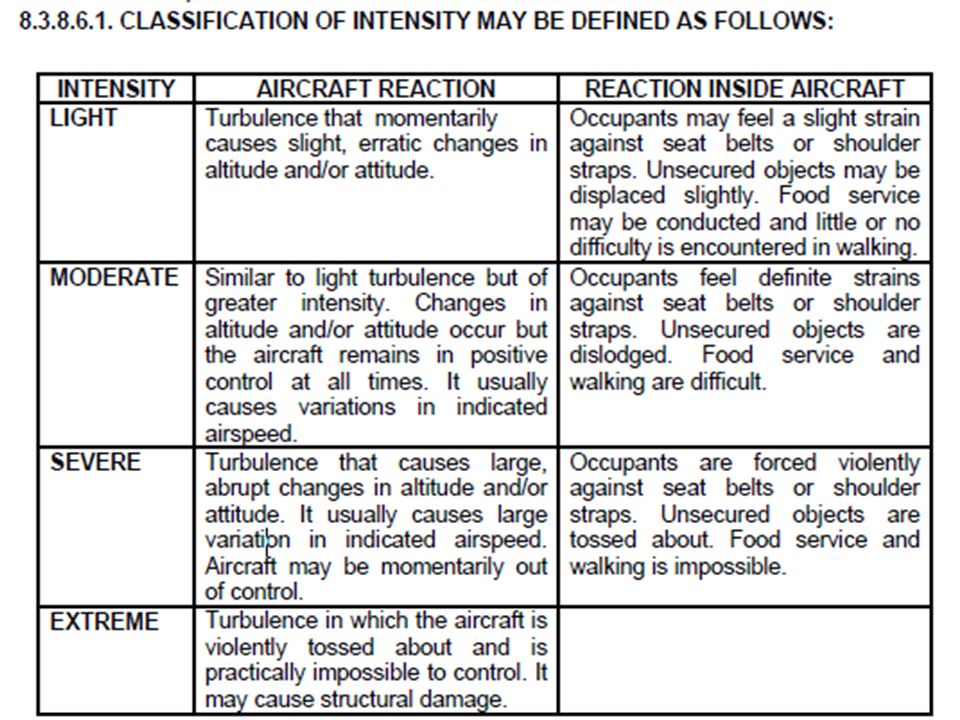


>")


 Saulo Da Silva>")
 taking all reasonable steps to fully exploit the existing capacity of the air navigation system; b) developing plans.>")


 and Radio Navigation (R/N) services R/T Communications English is the standard language for all commercial flights,>")


