Download presentation
Presentation is loading. Please wait.

1
DESIGN OF FLEXIBLE PAVEMENT
BY RABINDRA KUMAR ACHARYA SE (D&P),O/O CE NH ODISHA
,O/O CE NH ODISHA.")
2
A pavement structure that maintains intimate contact with the load and distribute the load to the foundation through aggregate interlocking, particle friction and cohesion is called a flexible pavement. Cementing agent like bitumen is used at the top layer of the pavement to prevent wearing of the pavement

3
A TYPICAL TWO LANE HIGHWAY

4
TYTICAL CROSS SECTION OF THE TWO LANE HIGHWAY
DIFFERENT LAYERS OF THE PAVEMENT WITH GRANULAR BAES AND SUB BAES

6
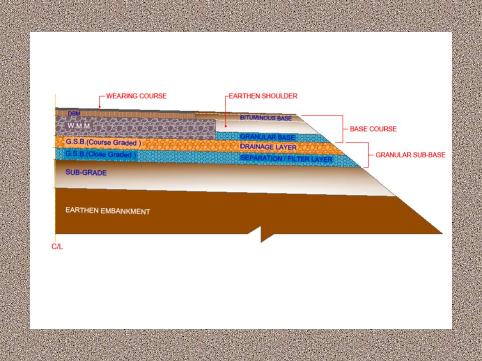
DIFFERENT LAYERS OF THE PAVEMENT
Wearing course BITUMENOUS Bituminous base Granular base GRANULAR GSB DRAINAGE LAYER GSB FILTER /SEPARATION LAYER SUB GRADE SOIL BMBANKMENT

7
Granular sub – base The material may consists of natural sand, moorum, gravel, laterite, kankar, brick metal, crushed stone, crushed slag, reclaimed crushed concrete/reclaimed asphalt pavement or combination thereof meeting the prescribed grading and physical requirements. Table (MOST)- Physical Requirement of Materials for GSB AGGREGATE IMPACT VALUE (AIV) I S 2386 (PART- 4) OR IS 5640 40 MAXIMUN LIQUID LIMIT (LL) IS 2720 PART - 5) MAXIMUN 25 PLASTICITY INDEX (PI) MAXIMUM 6 CBR AT 98% DRY DENSITY MINIMUM 30
- Physical Requirement of Materials for GSB. AGGREGATE IMPACT VALUE (AIV) I S 2386 (PART- 4) OR IS MAXIMUN. LIQUID LIMIT (LL) IS 2720 PART - 5) MAXIMUN 25. PLASTICITY INDEX (PI) MAXIMUM 6. CBR AT 98% DRY DENSITY. MINIMUM 30.")
8
Granular sub – base cont…
GSB IS OF TWO LAYERS 1) Filter/ Separation layer – Close Graded. Placed above the sub grade to prevent the ingress of sub grade soil to the drainage layer above it. 2) Drainage layer – Coarse Graded. Permeability – 300m/day. Fineness passing 75 micron < 2% . Drainage layer is very important for the internal drainage in the pavement
 Filter/ Separation layer – Close Graded. Placed above the sub grade to prevent the ingress of sub grade soil to the drainage layer above it. 2) Drainage layer – Coarse Graded. Permeability – 300m/day. Fineness passing 75 micron < 2% . Drainage layer is very important for the internal drainage in the pavement")
9
INTERNAL DRAINAGE IN THE PAVEMENT
Performance of the pavement is seriously affected if adequate drainage measures to prevent the accumulation of water in the pavement structure are not taken. The sub-grade and the granular layers with entrapped water would be subjected to large pore water pressure under heavy load causing erosion to the unbound layers. Drainage measures are very important when the road is: 1) In cutting sections 2) Built on low permeability soil 3) In heavy rainfall/snow fall region AS MOST OF THE REGIONS OF ODISHA GET RAINFALL 1500MM / YEAR, INTERNAL DRAINAGE IS A MUST FOR ROADS HAVING HIGH VOLUME OF TRAFFIC
 In cutting sections. 2) Built on low permeability soil. 3) In heavy rainfall/snow fall region. AS MOST OF THE REGIONS OF ODISHA GET RAINFALL 1500MM / YEAR, INTERNAL DRAINAGE IS A MUST FOR ROADS HAVING HIGH VOLUME OF TRAFFIC.")
10
CONTINUE………. TO ENSURE INTERNAL DRAINASE AND TO PREVENT ACCUMULATION OF WATER BELOW THE PAVEMENT LAYERS FOLLOWING GUIDELINES SHOULD BE FOLLOWED 1) BOTTOM OF THE SUB – GRADE , 0.6 M – 1.0 M ABOVE THE HFL/WATER TABLE 2) SAND BLANKEK AS CAPLLARY CUOFF, IF SUB – GRADE IN THE ZONE OF CAPILLARY SATURATION 3) TRENCH TYPE SECTIONS SHOUD NOT BE PROVIDED. IN SLOPES SPECIAL DRAINAGE ARRANGEMENT SHOULD BE MADE. 4) DRAINAGE LAYER (GSB) SHOULD BE EXTENDED FULL WIDTH OF THE EMBANKMENT 5) SUITABLE ROAD SIDE DRAIN FOR SURFACE RUNOFF 6) PREVENT ENTERING OF WATER AT THE EDGE OF BITUMINOUS LAYER a) proper cross slop of shoulders (4%) b) shoulders with impervious material c) base course extended 300 – 450 mm to prevent ingress of water to carriage way d) paved shoulders for high volume traffic road e) periodic maintenance of shoulders
 BOTTOM OF THE SUB – GRADE , 0.6 M – 1.0 M ABOVE THE HFL/WATER TABLE. 2) SAND BLANKEK AS CAPLLARY CUOFF, IF SUB – GRADE IN THE ZONE OF CAPILLARY SATURATION. 3) TRENCH TYPE SECTIONS SHOUD NOT BE PROVIDED. IN SLOPES SPECIAL DRAINAGE ARRANGEMENT SHOULD BE MADE. 4) DRAINAGE LAYER (GSB) SHOULD BE EXTENDED FULL WIDTH OF THE EMBANKMENT. 5) SUITABLE ROAD SIDE DRAIN FOR SURFACE RUNOFF. 6) PREVENT ENTERING OF WATER AT THE EDGE OF BITUMINOUS LAYER. a) proper cross slop of shoulders (4%) b) shoulders with impervious material. c) base course extended 300 – 450 mm to prevent ingress of water to carriage way. d) paved shoulders for high volume traffic road. e) periodic maintenance of shoulders.")
11
BEHAVIOUR OF PAVEMENT

12
.

13
.

14
DESIGN LIFE BASED ON THE RESPONSE OF THE PAVEMENT DUTO REPEATED LOADING THE FAILURE OF THE PAVEMENT OCCURES AT POINT 1,2,&3 POINT – 1 – TOP DOWN CRACKING – AT TOP LAYER OF BITUMINOUS LAYER POINT – 2 – BOTTOM UP CRACKING - AT BOTTOM LAYER OF BITUMINOUS LAYER POINT – 3 – RUTTING ( DEPRESSION) – AT SUB – GRADE DESIGN LIFE OF PAVEMENT 1) 20% OF SURFACE AREA CRACKING AND RUTTING UP TO 20MM FOR TRAFFIC UP TO 30 MSA 2) 10% OF SURFACE AREA CRACKING AND RUTTING UP TO 20MM FOR TRAFFIC > 30 MSA
 – AT SUB – GRADE. DESIGN LIFE OF PAVEMENT. 1) 20% OF SURFACE AREA CRACKING AND RUTTING UP TO 20MM FOR TRAFFIC UP TO 30 MSA. 2) 10% OF SURFACE AREA CRACKING AND RUTTING UP TO 20MM FOR TRAFFIC > 30 MSA.")
15
DESIGN TFAFFIC THE DESIGN METHOD OF THE CODE(IRC 37 – 2012) CONSIDER THE DESIGN TRAFFIC AS THE CUMULATIVE NUMBERS OF STANDARD AXIL TO BE CARRIED BY THE PAVEMENT DURING THE DESIGN LIFE STANDARD AXIL - SINGLE AXLI DUAL WHEEL OF 80 KN DESIGN LIFE - DESIGN PERIOD OF MORE THAN 15 YEARS IS CONSIDERED
 CONSIDER THE DESIGN TRAFFIC AS THE CUMULATIVE NUMBERS OF STANDARD AXIL TO BE CARRIED BY THE PAVEMENT DURING THE DESIGN LIFE. STANDARD AXIL - SINGLE AXLI DUAL WHEEL OF 80 KN. DESIGN LIFE - DESIGN PERIOD OF MORE THAN 15 YEARS IS CONSIDERED.")
16
COMPUTATION OF DESIGN TRAFFIC

17
IRC:37-2012 – Lane Distribution factor
Single Lane – 100% of two-way traffic Two lane Single Carriageway – 50% of To-way Four Lane Single Carriageway – 40% of Two-way Dual Two-lane – 75 % of one way for; Dual Three lane – 60%; Dual Four lane – 45% VDF- VEHICLE DAMAGE FACTOR

18
Sub - grade Top 500mm of the embankment is the sub grade of the pavement which is the foundation of the pavement. It may be of in-situ soil, selected soil or stabilized soil It should be well compacted to limit the scope of rotting. Minimum 97% compaction Minimum CBR should be 8% for road having 450 commercial vehicle per day or more. 4 days soaked CBR of Each soil used in the sub-grade should be taken and 90th percentile for high volume road and 80th for other roads are taken for design

19
Effective CBR The effective CBR of the selected sub grade is considered for design when there is significant difference between the embankment soil and the sub-grade RELATION BETWEEN RESILIENT MODULUS AND EFFECTIVR CBR Resilient modulus is the measure of elastic behavior and determined from recoverable deformation in the laboratory test Fig. 5.1 Effective CBR OF sub- grade (IRC )
")
20
.Granular base and sub - base
Unbound GSB – PI and LL requirement of 25% and <6% Lower Layer of GSB – Filter; Upper layer – Drainage (LA Abrasion <40%; % Passing mm < 2%) Granular base course The base maybe of wet mix macadam (WMM),Water bound macadam (WBM),Crushed run macadam(CRM),Reclaimed concrete etc . Relevant specification of MORTH/IRC to be followed Resilient Modulus of GSB and Granular Base h = thickness of sub- base/base layer in mm Poisson’s ratio = 0.35
 Granular base course. The base maybe of wet mix macadam (WMM),Water bound macadam (WBM),Crushed run macadam(CRM),Reclaimed concrete etc . Relevant specification of MORTH/IRC to be followed. Resilient Modulus of GSB and Granular Base. h = thickness of sub- base/base layer in mm. Poisson’s ratio =")
21
Bituminous Layers POISSON’S RATIO = 0.35 FOR TEMP. UP TO 35⁰ C
RESILIENT MODULOUS OF BITUMINOUS MATERIAL AS PER IRC POISSON’S RATIO = 0.35 FOR TEMP. UP TO 35⁰ C = 0.50 FOR TEMP. > 35⁰ C

22
.

23
Principles of pavement design
A flexible pavement is modeled as an elastic multilayered structure. The stresses and strains at different locations are computed using linear layered elastic model. IITPAVE software can be used to compute the stresses and strains. At location 1 near the edge of tyres strains (Єt ) are much higher, which may cause top down cracking. High modulus rut resistant and fatigue resistant mix is used to prevent top - down cracking .
 are much higher, which may cause top down cracking. High modulus rut resistant and fatigue resistant mix is used to prevent top - down cracking .")
24
Fatigue model At location 2 the tensile strain (Єt ) developed at the bottom of the bituminous layer and creates micro cracks for every load repetition. Design life of the pavement in terms of cumulative numbers of standard axils which will cause fatigue failure of the bituminous layer has been developed based on pavement performance data collected by the researchers.
 developed at the bottom of the bituminous layer and creates micro cracks for every load repetition. Design life of the pavement in terms of cumulative numbers of standard axils which will cause fatigue failure of the bituminous layer has been developed based on pavement performance data collected by the researchers.")
25
Fatigue model continue…
The two equations for fatigue model are --(f1) --(f2) 80% reliability is for Nf up to 30msa with VG 30 bitumen 90% reliability is for Nf > 30msa with VG 40 bitumen
 --(f2) 80% reliability is for Nf up to 30msa with VG 30 bitumen. 90% reliability is for Nf > 30msa with VG 40 bitumen.")
26
Fatigue model continue…
Generally design mix with 4.5% air void ( Va ) and bitumen content 4.5% by wt. of mix, (which volume would comes to 11.5% (Vb ))were used for pavements. Further research recommended incorporation of a factor ‘C’ to take account of Va & Vb Incorporating Equation f2 becomes Considering 3% air voids and 13% binder volume, the fatigue equation gets a coefficient of 2.021
 and bitumen content 4.5% by wt. of mix, (which volume would comes to 11.5% (Vb ))were used for pavements. Further research recommended incorporation of a factor ‘C’ to take account of Va & Vb. Incorporating Equation f2 becomes. Considering 3% air voids and 13% binder volume, the fatigue equation gets a coefficient of")
27
Fatigue model continue…
The fatigue model equations (f1 & f2) gives fatigue lives 20% crack area of the bituminous layer at reliability level of 80% and 90% respectively at the end of design period. It means---- 1) 20% of area may have 20% crack for 80% reliability ( design traffic up to 30 msa) VG-30 may be used 2) 10% of area may have 20% crack for 90 % reliability ( design traffic > 30 msa) VG -40 should be used less Va and higher Vb
 gives fatigue lives 20% crack area of the bituminous layer at reliability level of 80% and 90% respectively at the end of design period. It means---- 1) 20% of area may have 20% crack for 80% reliability ( design traffic up to 30 msa) VG-30 may be used. 2) 10% of area may have 20% crack for 90 % reliability ( design traffic > 30 msa) VG -40 should be used less Va and higher Vb.")
28
Rutting model Rutting is the permanent deformation in the pavement usually occurring longitudinally along the wheel path. Rutting may partly be caused by deformation of sub – grade and granular layer. Granular layer laid on a strong sub- grade has a high resilient modulus and resist rutting when not highly stressed. Due to secondary compaction under heavy traffic load and high temperature the bituminous layer may undergo rutting. It is recommended to provide rut resistant bituminous mixes using higher viscosity grade bitumen or modified bitumen for avoiding rutting of bituminous layer

29
Rutting model cont…. At location 3 vertical sub - grade strain (Єv ) on the top of sub – grade are conventionally considered as critical parameter for pavement design to limit rutting in the pavement. The limiting rutting is recommended as 20mm in 20% of length for design traffic up to 30 msa (80% reliability level ) and 10% of length for design traffic > 30 msa (90% reliability level )
 on the top of sub – grade are conventionally considered as critical parameter for pavement design to limit rutting in the pavement. The limiting rutting is recommended as 20mm in 20% of length for design traffic up to 30 msa (80% reliability level ) and 10% of length for design traffic > 30 msa (90% reliability level )")
30
Rutting model cont…. Like fatigue model design life of the pavement in terms of cumulative numbers of standard axils which will cause rutting failure of the sub - grade has been developed based on pavement performance data collected by the researchers - 80% reliability level - 90% reliability level

31
Pavement design procedures
Design catalogues – IRC – design catalogues are provided in the code for different layer combinations, Sub- grade CBR 3% to 15% and cumulative axils from 2 msa to 150 msa. These plates can be used to design the pavement. Using IITPAVE – for the required traffic volume, material property of different layers and layer thickness the strains can be calculated. These strains can se compared with the allowable strains as predicted by the fatigue and rutting models. A satisfactory design can be achieved through iterative process by varying layer thickness if necessary.

32
Pavement design procedures
Design catalogues – IRC (Sample plate)
")
33
Pavement design procedures
DETAILED CALLATIOS STAPE WISE IS MADE ON A SPREAD SHEET AND CHECKED BY IITPAVE

34
OTHER DIFFERENT COMBINATIOS
IN ADDITION TO THE GRANULAR PAVENENT LAYRERS SOME OTHER COMBINATION OF PAVEMENT LAYERS ARE SPECIFIED IN IRC

35
BITUMINOUS LAYER (BC +DBM
subgrade COMBINATION 2 With cemented sub-base/base and a crack relief layer BITUMINOUS LAYER (BC +DBM 100WMM crack relief layer Cemented base Cemented subbase Sub - grade

36
COMBINATION - 3 With cemented sub-base/base and a crack relief SAMI layer BITUMINOUS LAYER (BC +DBM Stress Absorbing Membrane layer(SAMI) layer Cemented base Cemented sub base Sub- grade
 layer. Cemented base. Cemented sub base. Sub- grade.")
37
COMBINATION - 4 With RAP/ RAP+ virgin aggregate - foam bitumen or emulsion stabilized Bituminous layer(BC+DBM) RAP or RAP+ aggregate + bit emulsion or foamed bitumen Cemented subbase Sub - grade
 RAP or RAP+ aggregate + bit emulsion or. foamed bitumen. Cemented subbase. Sub - grade.")
39
Thank you

Similar presentations


>")


