Download presentation
Presentation is loading. Please wait.

1
Programming PIC 16F84A in Assembly

3
PIC16F84 pin-out and required external components

6
Programing

7
If you type a ; (semicolon) anywhere in your program, the compiler will ignore anything after it until the carriage return.
 anywhere in your program, the compiler will ignore anything after it until the carriage return.")
8
The Registers. A register is a place inside the PIC that can be written to, read from or both.

9
Bank 1 is used to control the actual operation of the PIC for example to tell the PIC which bits of Port A are input and which are output Bank 0 is used to manipulate the data example is as follows: Let us say we want to make one bit on Port A high. 1.go to Bank 1 to set the particular bit, or pin, on Port A as an output. 2.come back to Bank 0 and send a logic 1 (bit 1) to that pin.
 to that pin..")
10
The most common registers in Bank 1 we are going to use are STATUS It allows us to come back to Bank 0 TRISA It allows us to select which pins on Port A are output and which are input It allows us to select which pins on Port B are output and which are input TRISB

11
How to switch between Bank 0 and Bank 1? To change from Bank 0 to Bank 1 we tell the STAUS register. We do this by setting bit 5 of the STATUS register to 1. To switch back to Bank 0, we set bit 5 of the STATUS register to 0. The STATUS register is located at address 03h (the ‘h’ means the number is in Hexadecimal).
..")
12
Working With Banks Bank 1

13
File Address Bank 1

14
Bank 0

15
File Address

16
Setting ports as inputs or outputs These are located at addresses 85h and 86h respectively. To program a pin to be an output or an input, we simply send a 0 or a 1 to the relevant bit in the register. This can either be done in binary, or hex

17
working with Port A Port A we have 5 pins, and hence 5 bits. to set one of the pins to input, I send a ‘1’ to the relevant bit. The bits are arranges in exactly the same way as the pins, in other words bit 0 is RA0, bit 1 is RA1, bit 2 is RA2 and so on.

18
Example. Set pins of port as follow RA0, RA3 and RA4 as outputs RA1 and RA2 as inputs

19
To send one of our output pins high, we simply send a ‘1’ to the corresponding bit in our PORTA or PORTB register. Sending Data via port A Perform a check to see if the particular corresponding bit is set to high (1) or set to low (0) Reading DATA from Port A
 or set to low (0) Reading DATA from Port A.")
20
Understanding W register If you assign another value to W, its contents are overwritten. The W register is a general register in which you can put any value that you wish. Once you have assigned a value to W, you can add it to another value, or move it.

21
Configure Port A as the following PA0,PA3,PA4 as output PA1, PA2 as input An Example Code.

23
General Algorithm 1. Switch from Bank 0 to Bank 1 2. Move the value of port setting “00110” to register w This can be done by setting bit 5 in the status register into 1 3. Set the TRISA register by moving the content of W to TIRSA register 4. Return to Bank 0.

25
BSF 03h,5 MOVLW 06h MOVWF 85h BCF 03h,5

26
BSF 03h,5 The BSF Means Bit Set F. The letter F means that we are going to use a memory location, or register We are using two numbers after this instruction – 03h, which is the STATUS register address – 5 which corresponds to the bit number Meaning : Set bit 5 in address 03h to 1” Use : to switch from Bank 0 to Bank 1. We are now in Bank 1

27
MOVLW b'00110' Meaning : putting the binary value 00110 into general purpose register W. MOVLW 06h in hex MOVLW means ‘Move Literal Value Into W

28
It is used to put value (which is in W) onto our TRISA register to set up the port MOVWF 85h Meaning : Move The Contents Of W Into The Register Address That Follows
 onto our TRISA register to set up the port MOVWF 85h Meaning : Move The Contents Of W Into The Register Address That Follows")
29
BCF 03h,5 It means “Bit Clear F” It is used to set bit 5 on our STAUS register to 0 We are now back in Bank 0.

30
Writing To the Ports

31
bcf 03h,5 ; Come back to Bank 0 bsf 03h,5 ;Go to Bank 1 movlw 00h ;Put 00000 into W movwf 85h ;Move 00000 onto TRISA – all pins set to output Example : write a program which turn on a LED connected to port A pin2 movlw 02h movwf 05h

33
Turn The LED off:

34
What we want is for the LED to turn on then off continuously. We do this by getting the program to go back to the beginning.

35
Replacing Numbers to Names

37
Each instruction takes one clock cycle to complete. If we are using a 4MHz crystal, then each instruction will take 1/4MHz, or 1uS to complete. As we are using only 5 instructions, the LED will turn on then off in 5uS. Why you can’t see the blinking Led? What do you need ?

38
Principle of the delay we continue on our way through the program. count down from a previously set number when it reaches zero, we stop counting The zero value indicates the end of the delay

39
define a constant to use as our counter.COUNT decide how big a number to start counting from the largest number we can have is 255, or FFh in hex. If we try and assign the value FFh, we will get an error when we come to compile the program. This is because location FFh is reserved, and so we can’t access it. So, how do we assign an actual number

47
Subroutines

51
Reading from the I/O ports

53
Check If The Pin Is High Or Low The BTFSC instruction means ‘Do a bit test on the register and bit we specify. If it is a 0, then we skip the next instruction BTFSC BTFSS BTFSS means ‘Do a bit test in the register and bit we specify. If it is set to a 1, then we skip the next instruction.

54
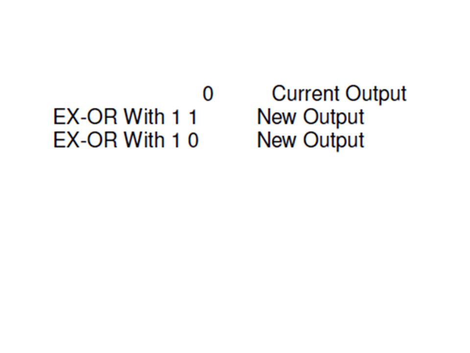
Code Optimization Exclusive OR function

56
to turn our LED on and off, we just need two lines

57
How it is work?

Similar presentations


 1 Prepared By: Associate Prof. Dr Masri Ayob.>")


