Download presentation
Presentation is loading. Please wait.

1
Prof. Shrikant M. Harle Asst prof. Dept of Civil Engg PRMCEAM
Flat Slab Prof. Shrikant M. Harle Asst prof. Dept of Civil Engg PRMCEAM

2
Introduction Common practice of design and construction is to support the slabs by beams and support the beams by columns. This may be called as beam-slab construction. The beams reduce the available net clear ceiling height.

3
Hence in warehouses, offices and public halls some times beams are avoided and slabs are directly supported by columns. This types of construction is aesthetically appealing also. These slabs which are directly supported by columns are called Flat Slabs.

4
Typical Flat slab (without drop & column head)
")
5
The column head is some times widened so as to reduce the punching shear in the slab.
The widened portions are called column heads. The column heads may be provided with any angle from the consideration of architecture but for the design, concrete in the portion at 45º on either side of vertical only is considered as effective for the design

6
Slab without drop & column with column head

7
Moments in the slabs are more near the column.
Hence the slab is thickened near the columns by providing the drops Sometimes the drops are called as capital of the column.

8
Slab with drop & column without column head

9
Types of flat slabs Slabs without drop and column head
Slabs without drop and column with column head Slabs with drop and column without column head Slabs with drop and column head

10
Slab with drop & column with column head

11
The portion of flat slab that is bound on each of its four sides by centre lines of adjacent columns is called a panel. A panel may be divided into column strips and middle strips. Column Strip means a design strip having a width of 0.25L1 or 0.25L2, whichever is less. The remaining middle portion which is bound by the column strips is called middle strip.

12
Panels, column strip & middle strip in y-direction

13
Proportioning of Flat slab
Drops The drops when provided shall be rectangular in plan, and have a length in each direction not less than one third of the panel in that direction. For exterior panels, the width of drops at right angles to the non continuous edge and measured from the centre-line of the columns shall be equal to one half of the width of drop for interior panels.

14
Column Heads Where column heads are provided, that portion of the column head which lies within the largest right circular cone or pyramid entirely within the outlines of the column and the column head, shall be considered for design purpose

15
Thickness of Flat Slab From the consideration of deflection control IS specifies minimum thickness in terms of span to effective depth ratio. For this purpose larger span is to be considered. If drop is provided, then the maximum value of ratio of larger span to thickness shall be 40, if mild steel is used 32, if Fe 415 or Fe 500 steel is used

16
If drops are not provided or size of drops do not satisfy the specification, then the ratio shall not exceed 0.9 times the value specified above i.e., 40 X 0.9 = 36, if mild steel is used. 32 X 0.9 = 28.8, if HYSD bars are used It is also specified that in no case, the thickness of flat slab shall be less than 125 mm.

17
Determination of BM & SF
For this IS permits use of any one of the following two methods: The Direct Design Method The Equivalent Frame Method

18
Direct Design Method This method has the limitation that it can be used only if the following conditions are fulfilled: There shall be minimum of three continuous spans in each directions. The panels shall be rectangular and the ratio of the longer span to the shorter span within a panel shall not be greater than 2. The successive span length in each direction shall not differ by more than one-third of longer span.

19
The design live load shall not exceed three times the design dead load.
The end span must be shorter but not greater than the interior span. It shall be permissible to offset columns a maximum of 10 percent of the span in the direction of the offset not withstanding the provision in (b).
.")
20
Total Design moment The absolute sum of the positive and negative moment in each direction is given by M0 = Total moment W = Design load on the area L2 X Ln Ln = Clear span extending from face to face of columns, capitals, brackets or walls but not less than 0.65 L1 L1 = Length of span in the direction of M0; and L2 = Length of span transverse to L1

21
In taking the values of Ln, L1 and L2, the following clauses are to be carefully noted:
Circular supports shall be treated as square supports having the same area i.e., squares of size 0.886D. When the transverse span of the panel on either side of the centre line of support varies, L2 shall be taken as the average of the transverse spans. When the span adjacent and parallel to an edge is being considered, the distance from the edge to the centre-line of the panel shall be substituted for L2.

22
Distribution of BM in to +ve & -ve moments
The total design moment M0 in a panel is to be distributed into –ve moment and +ve moment as specified below: In an interior span: Negative Design Moment 0.65 M0 Positive Design Moment 0.35 M0

23
In an end span Interior negative design moment Positive design moment
Exterior negative design moment

24
where I is the ratio of flexural stiffness at the exterior columns to the flexural stiffness of the slab at a joint taken in the direction moments are being determined and is given by Kc = Sum of the flexural stiffness of the columns meeting at the joint; and Ks = Flexural stiffness of the slab, expressed as moment per unit rotation

25
Distribution of Moments Across the Panel Width in a Column Strip

26
Moments in Columns In this type of constructions column moments are to be modified as suggested in IS 456–2000 [Clause No ].

27
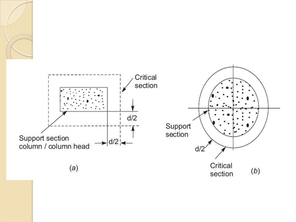
Shear Force The critical section for shear shall be at a distance d/2 from the periphery of the column/capital drop panel. Hence if drops are provided there are two critical sections near columns. The shape of the critical section in plan is similar to the support immediately below the slab as shown in Fig.

29
For columns sections with re-entrant angles, the critical section shall be taken as indicated in Fig

30
In case of columns near the free edge of a slab, the critical section shall be taken as shown in Fig.

31
The nominal shear stress may be calculated as
V – is shear force due to design bo – is the periphery of the critical section d – is the effective depth

32
The permissible shear stress in concrete may be calculated as ksτc, where ks = but not greater than 1, where is the ratio of short side to long side of the column/capital; and If shear stress – no shear reinforcement are required. If , shear reinforcement shall be provided. If shear stress exceeds flat slab shall be redesigned.

Similar presentations


: Redesign the stair shown in Example (10.1) if it is a cantilever type of a clear span of 1.6 m. Solution : Minimum stair thickness required.>")


