Download presentation
Presentation is loading. Please wait.

1
W Simple Circuit

4
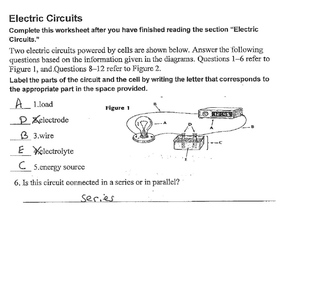
Lesson 5: Electrical Circuits Prelab: 1) What is a circuit? __________________________________________________________________ 2) Identify the three basic parts of a circuit? A._________________________ B._________________________ C._________________________
 Identify the three basic parts of a circuit. A._________________________ B._________________________ C._________________________.")
5
Lesson 5: Electrical Circuits Prelab: 1) What is a circuit? A complete closed path through which electrical charges flow 2) Identify the three basic parts of a circuit? A. Energy Source - Where the electrical current originates B. Wires - connect the power source to the load C. Load - uses the electrical current
 Identify the three basic parts of a circuit. A. Energy Source - Where the electrical current originates B. Wires - connect the power source to the load C. Load - uses the electrical current.")
6
3) Look in your lab kit. Identify the following materials.
 Look in your lab kit. Identify the following materials.")
7
Wires Switch Energy Source Load - Lightbulb

8
Inquiry 5.1: Lighting a Lightbulb 1) Use the materials in your kit to build a circuit in which a single lightbulb will tun on and off using a switch. 2) Draw a picture below of the circuit you created. - +
 Draw a picture below of the circuit you created")
9
3) Now use the electrical symbols chart to change your picture into an electrical diagram. W + -
 Now use the electrical symbols chart to change your picture into an electrical diagram. W + -")
10
4) Create a parallel circuit in which two bulbs can be turned on and off by a master switch. ( master switch is connected to the negative side of the battery). One lightbulb must stay on when the other is unscrewed from its base. __________________________________________________________________ 5) Now use your lab materials to build the diagram you created in number 4. W + - W
. One lightbulb must stay on when the other is unscrewed from its base. __________________________________________________________________ 5) Now use your lab materials to build the diagram you created in number 4. W + - W.")
11
Procedure: Constructing Circuits In this Inquiry your group will investigate circuits by connecting batteries, lightbulbs, and wire leads so that the lightbulbs will light in a number of different ways. Procedure: Complete the following circuits using your lab kit: Circuit A Create a circuit in which two lightbulbs can be turned on and off together. Draw the electrical diagram for the circuit:

12
C ircuit A W W - +

13
Circuit B Create a circuit in which two lightbulbs are connected to a power source, but one lightulb can be turned off, while the other lightbulb stays on continuously. Draw the electrical diagram for the circuit:

14
Circuit B W W - +

15
Circuit C Create a cicuit in which three lightbulbs connected to a power source. Lightbulb one can be turned off separately while lightbulb two and three can be turned on and off together. Draw the electrical diagram for the circuit:

16
Circuit C W W W - +

17
Circuit D Create a circuit in which three lightbulbs are connected to a power source. Each lightbulb must be able to turn on and off separately of each other. Draw the electrical diagram for the circuit:

18
W W W D + -

19
Reflecting What You’ve Done: A. Why is an electrical circuit that lights a lightbulb called a “closed” circuit? B. How can you tell that a circuit is closed? C. In an electrical diagram or schematic, how could you check to see if a circuit is closed? D. What does each of the following items do in a circuit: Battery Lightbulb Switch Wire E. A series circuit is one that has only one closed path around the circuit. Which of the circuits that you built are series circuits? F. A parallel circuit is one that has more than one closed path around the circuit. Which of the four circuit(s) that you built are parallel circuits? Why? G. Please read the article " Lightning's Fearsome Power" and answer the four questions at the end of the article.
 that you built are parallel circuits. Why. G. Please read the article Lightning s Fearsome Power and answer the four questions at the end of the article..")
20
W + - Quiz Review: Creating Circuits name the parts of a circuit by looking at the diagram. 1 2 3 4

21
W W - + W W - + Which circuit is a series? Which is parallel? How many paths are there for the electrical current to flow in each circuit below?

22
W W Is this an open or closed circuit? Why?

23
W W

24
W W W W Which circuit will keep the lightbulbs on continuously? W W

25
http://www.lightningsafety.noaa.gov/struck.htm Lightning 5 billion joules

28
Measuring Electrical Current in a Series Circuit Electric current is the flow of electric charge. To measure electrical current, you put a meter in an electrical circuit so that the electric charges pass through it. The meter measures how much electric charge passes through it each second. The electrical current is the amount of electric charge passing through the meter each second. Electrical current is measured in Amperes ( A ) which are often just called amps. The meter that measures electrical current is called an Ammeter. Ammeters often are marked in units of milliamperes ( mA ) because the current they measure are very small. A milliampere is 1/1000 of an amp. Prelab: 1) Examine your ammeter. What are the units of current on the ammeter? __________________________________________________________________ 2) What is the range of your ammeter? __________________________________________________________________ 3) How much current does the smallest interval on the scale measure? __________________________________________________________________
 which are often just called amps. The meter that measures electrical current is called an Ammeter. Ammeters often are marked in units of milliamperes ( mA ) because the current they measure are very small. A milliampere is 1/1000 of an amp. Prelab: 1) Examine your ammeter. What are the units of current on the ammeter. __________________________________________________________________ 2) What is the range of your ammeter. __________________________________________________________________ 3) How much current does the smallest interval on the scale measure. __________________________________________________________________.")
29
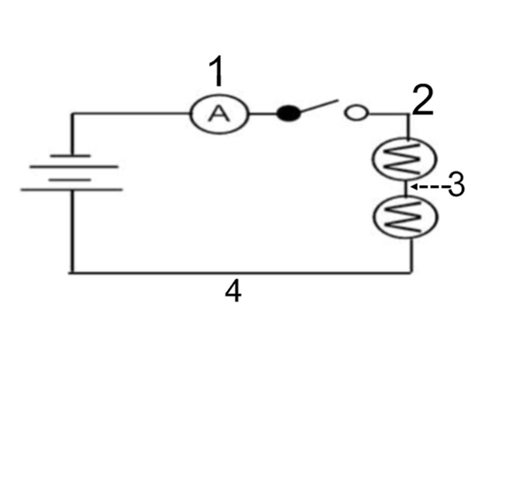
Procedure A: Measuring current in a series circuit 1) Set up the series circuit shown in the picture below using: Two batteries, a switch, two lightbulbs, and an ammeter. Make sure the switch is open. Place the Ammeter in position 1.

30
2) With the switch open, record the current through the ammeter. _____________ 3) Close the switch and record the current through the ammeter. _______________ 4) Hypothesis: If you were to move the ammeter to different places in the circuit would it have the same reading as above when the switch is open and closed? Discuss your reasoning.
 Close the switch and record the current through the ammeter. _______________ 4) Hypothesis: If you were to move the ammeter to different places in the circuit would it have the same reading as above when the switch is open and closed. Discuss your reasoning..")
31
Open the switch. Make sure the switch is open when you are moving the ammeter to different parts of the circuit. Then, close the ammeter to take the reading of the circuit. 5) Move the ammeter so that it is between the switch and the first lightbulb, in the series circuit. This is marked on the diagram as position ( 2 ). Record the current through the ammeter. _________________________ 6) Move the ammeter so that it is between the two lightbulbs in the series circuit. This is marked on the diagram as position ( 3 ). Record the current through the ammeter. _________________________ 7) Move the ammeter so that it is between the last lightbulb and the positive end of the battery in the series circuit. This is marked on the diagram as position ( 4 ). Record the current through the ammeter. _________________________
 Move the ammeter so that it is between the switch and the first lightbulb, in the series circuit. This is marked on the diagram as position ( 2 ). Record the current through the ammeter. _________________________ 6) Move the ammeter so that it is between the two lightbulbs in the series circuit. This is marked on the diagram as position ( 3 ). Record the current through the ammeter. _________________________ 7) Move the ammeter so that it is between the last lightbulb and the positive end of the battery in the series circuit. This is marked on the diagram as position ( 4 ). Record the current through the ammeter. _________________________.")
33
8) Was your hypothesis right or wrong? Explain the current flow in the system as you moved the ammeter to the four positions. Support your conclusion with evidence from your observations and measurements.

34
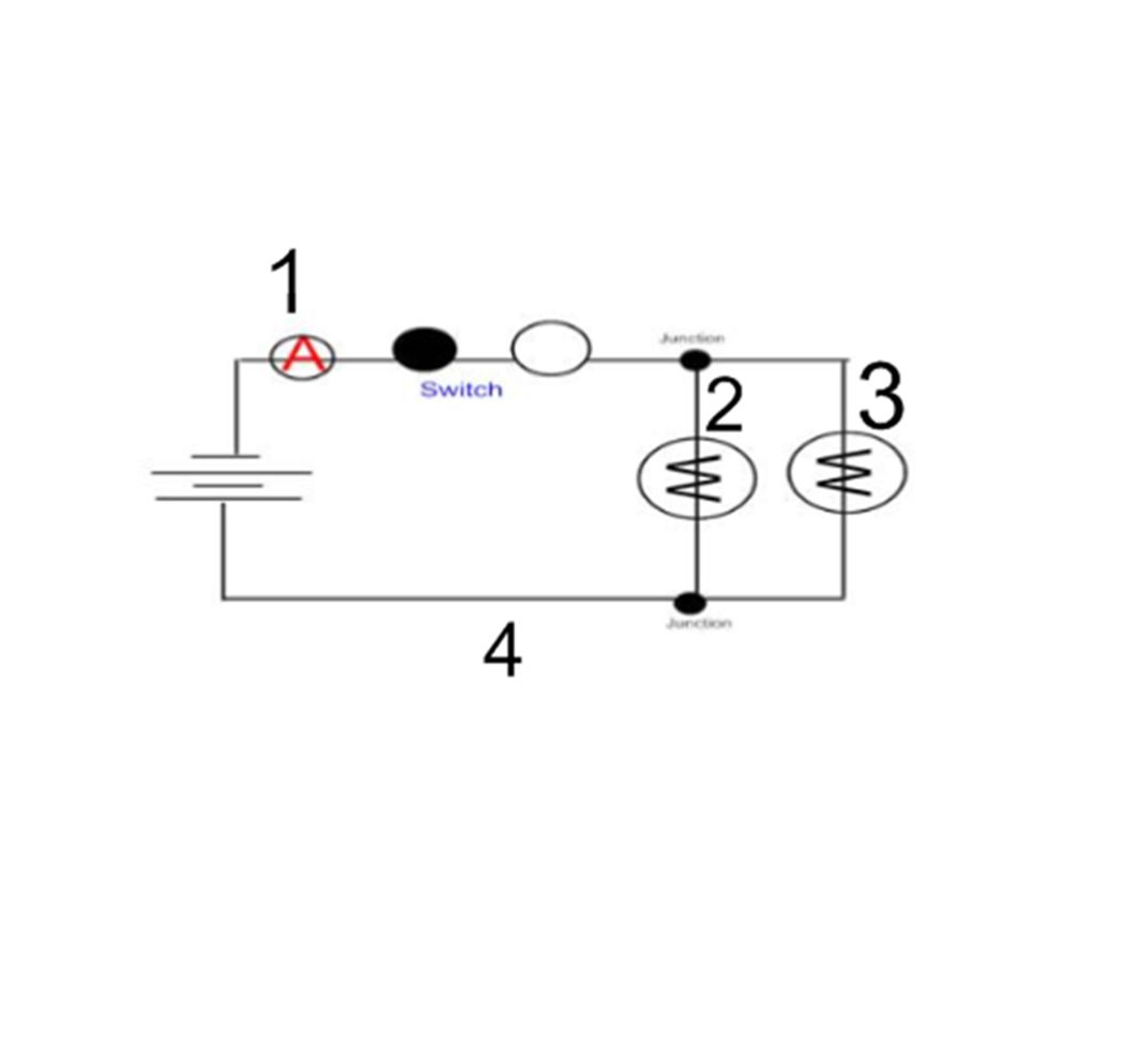
Procedure B: Measuring Current in a parallel circuit 9) Set up the parallel circuit shown in the picture below using: Two batteries, a switch, two lightbulbs, and an ammeter. Make sure the switch is open. Place the ammeter in position 1.

35
10) With the switch open, record the current through the ammeter. _____________ 11) Close the switch and record the current through the ammeter. ______________ 12) Hypothesis: If you were to move the ammeter to different places in the circuit would it have the same reading as above when the switch is open and closed. Discuss your reasoning.
 Close the switch and record the current through the ammeter. ______________ 12) Hypothesis: If you were to move the ammeter to different places in the circuit would it have the same reading as above when the switch is open and closed. Discuss your reasoning..")
36
Open the switch. Make sure the switch is open when you are moving the ammeter to different parts of the circuit. Then, close the ammeter to take the reading of the circuit. 13) Move the ammeter so that it is between the switch and the first lightbulb in the parallel circuit. This is marked on the diagram as position ( 2 ). Record the current through the ammeter. _________________________ 14) ) Move the ammeter so that it is between the switch and the second lightbulb in the parallel circuit. This is marked on the diagram as position ( 3 ). Record the current through the ammeter. _________________________ 15) ) Move the ammeter so that it is between the second lightbulb and the positive end of the battery in the series circuit. This is marked on the diagram as position ( 4 ). Record the current through the ammeter. _________________________ 16) ) Move the ammeter so that it is between the second junction and the positive end of the battery in the series circuit. This is marked on the diagram as position ( 5 ). Record the current through the ammeter. _________________________
 Move the ammeter so that it is between the switch and the first lightbulb in the parallel circuit. This is marked on the diagram as position ( 2 ). Record the current through the ammeter. _________________________ 14) ) Move the ammeter so that it is between the switch and the second lightbulb in the parallel circuit. This is marked on the diagram as position ( 3 ). Record the current through the ammeter. _________________________ 15) ) Move the ammeter so that it is between the second lightbulb and the positive end of the battery in the series circuit. This is marked on the diagram as position ( 4 ). Record the current through the ammeter. _________________________ 16) ) Move the ammeter so that it is between the second junction and the positive end of the battery in the series circuit. This is marked on the diagram as position ( 5 ). Record the current through the ammeter. _________________________.")
38
17) Was your hypothesis right or wrong? Explain the current flow in the system as you moved the ammeter to the four positions. Support your conclusion with evidence from your observations and measurements.

39
Procedure C: Investigating The direction of Current 17. Set up the circuit as shown below:

40
18. Close the switch. Observe the motion of the fan blade. 19. Discuss the following question with your partner: What will happen if you reverse the leads connected to the battery and close the switch? ________________________________________________________________________________ ____________________________________________________ 20. Reverse the wire leads to the battery and close the switch in the circuit. Record what happens to the fan. ( Move the wire on the negative end of the battery to the positive end, and move the wire on the negative end of the battery to the positive) 21. Propose an explanation with your group for why the fan behaves as it does.
 21. Propose an explanation with your group for why the fan behaves as it does..")
41
Measuring Current Review

42
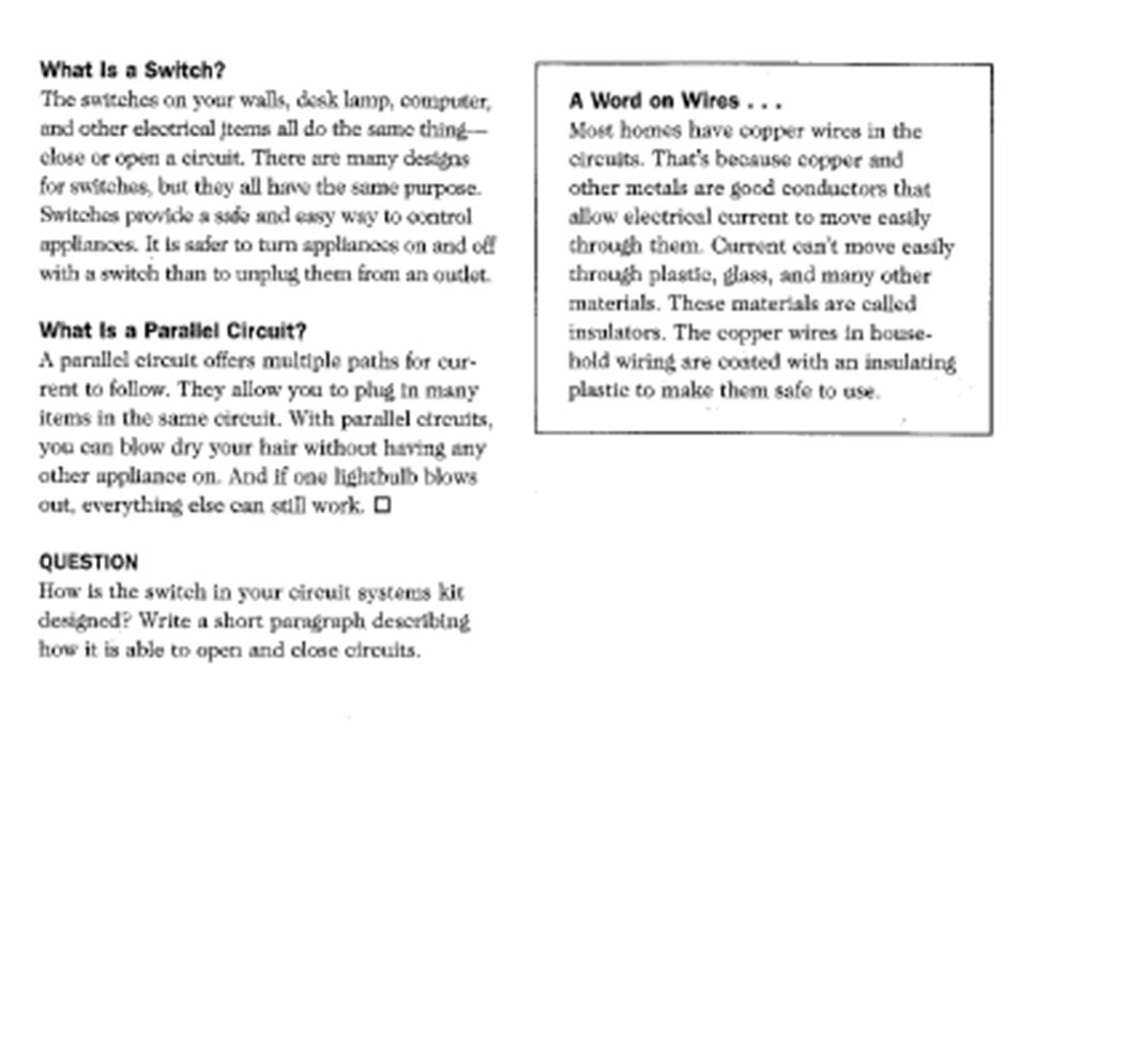
Switches: Opening switches stops the flow of current in a series system. In a parallel circuit, opening a switch will stop the current to a specific part of the circuit. if there is a master switch, opening the master switch will open the ciruit no matter if it is series or parallel.

43
Since this is a series circuit the current is the same throughout the circuit.

44
The current must now divide itself when it reaches the junction, but the total current in the system remains the same. Line 1 Line 2 Current at spot 1 = 450 mA Line 1= 220 mA Line 2= 225 mA

45
Current flows from negative to positive through the motor spinning it clockwise. Switching the wires switches the direction of current through the motor and causes the motor to spin in the opposite direction, making the fan blade spin in the opposite direction.

46
Reflecting What you’ve Done A. How did opening the switch affect the current? B. How did opening the switch in the circuit affect the lightbulb(s)? C. What do you think the current does in an electrical circuit? D. Consider the results of all three inquiries. What can you conclude about electrical current in closed circuits?
. C. What do you think the current does in an electrical circuit. D. Consider the results of all three inquiries. What can you conclude about electrical current in closed circuits .")
54
lab 10

61
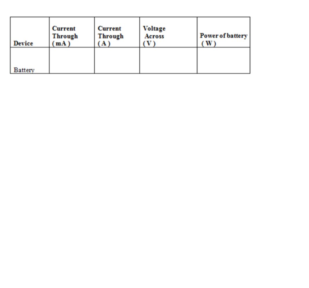
V A W

64
V A W W V V 1 2

66
Review

67
350 0.35 2.20.77 490 0.49 1.7 0.83 Uncertainty: Was the needle "zeroed" before the measurement Is all the energy in the system conserved or is some lost.

68
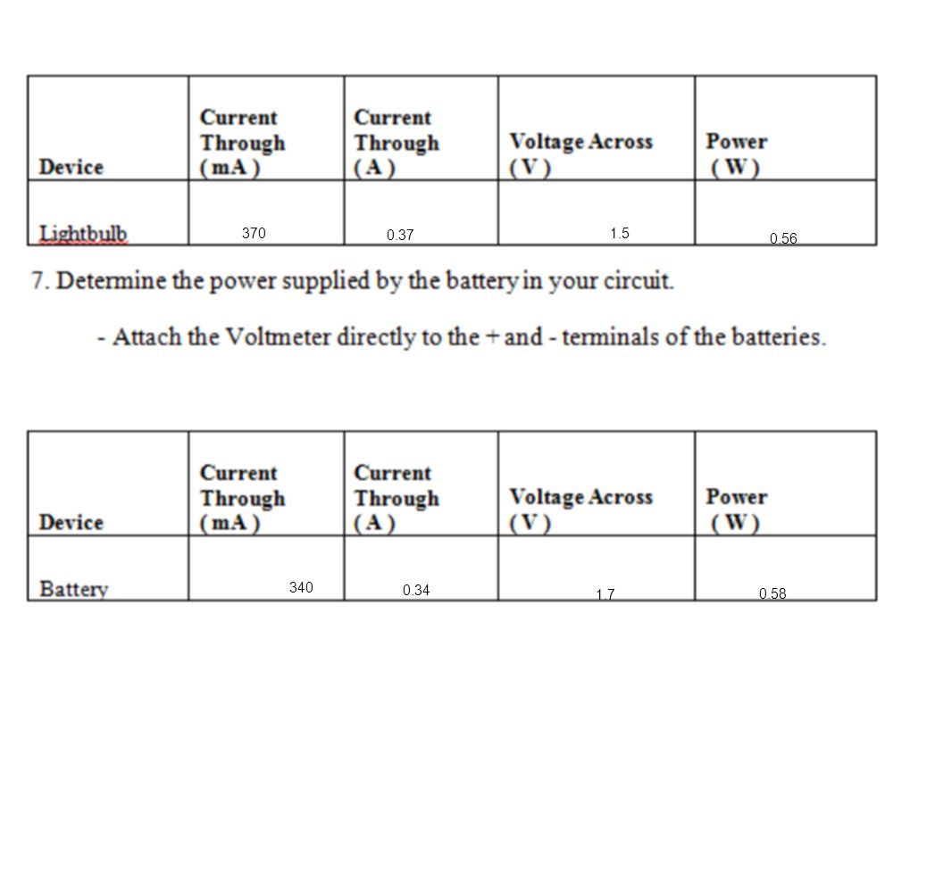
370 0.37 1.5 0.56 340 0.34 1.7 0.58

69
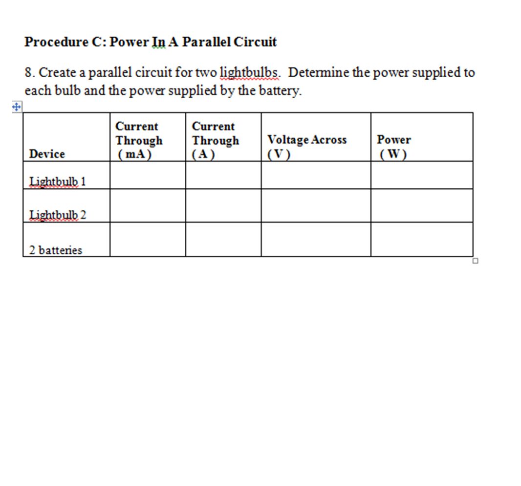
790 0.79 2.2 0.41 0.38 410 380 0.902 0.84 1.74 The power of the two bulbs = the total power of the batteries

77
Measuring Current Review

78
Switches: Opening switches stops the flow of current in a series system. In a parallel circuit, opening a switch will stop the current to a specific part of the circuit. if there is a master switch, opening the master switch will open the ciruit no matter if it is series or parallel.

79
Since this is a series circuit the current is the same throughout the circuit. 0.65A

80
The current must now divide itself when it reaches the junction, but the total current in the system remains the same. Line 1 Line 2 Current at spot 1 = 0.65A Line 1= 0.35A Line 2= 0.30A 0.65A 0.35A 0.30A 0.65A

81
Current flows from negative to positive through the motor spinning it clockwise. Switching the wires switches the direction of current through the motor and causes the motor to spin in the opposite direction, making the fan blade spin in the opposite direction.

82
Review

83
350 0.35 2.20.77 490 0.49 1.7 0.83 Uncertainty: Was the needle "zeroed" before the measurement? Is all the energy in the system conserved or is some lost? Does the device measure accurately?

84
370 0.37 1.5 0.56 340 0.34 1.7 0.58
85
790 0.79 2.2 0.41 0.38 410 380 0.902 0.84 1.74 The power of the two bulbs = the total power of the batteries

86
A 1 2 3 0.5 A Series or parallel? What will be the Current reading at points 2? 3?

87
A A A 1 2 3 1.0 A Series or parallel? What is the current at ammeter 2 and 3?

88
What is the difference between these two circuits?

89
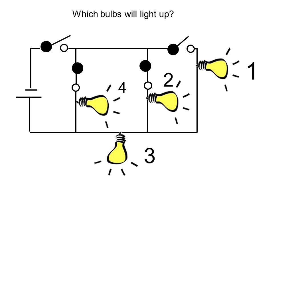
1 2 3 4 Which bulbs will light up?

90
1 2 3 4

91
1 2 3 4
92
1 2 3 4

98
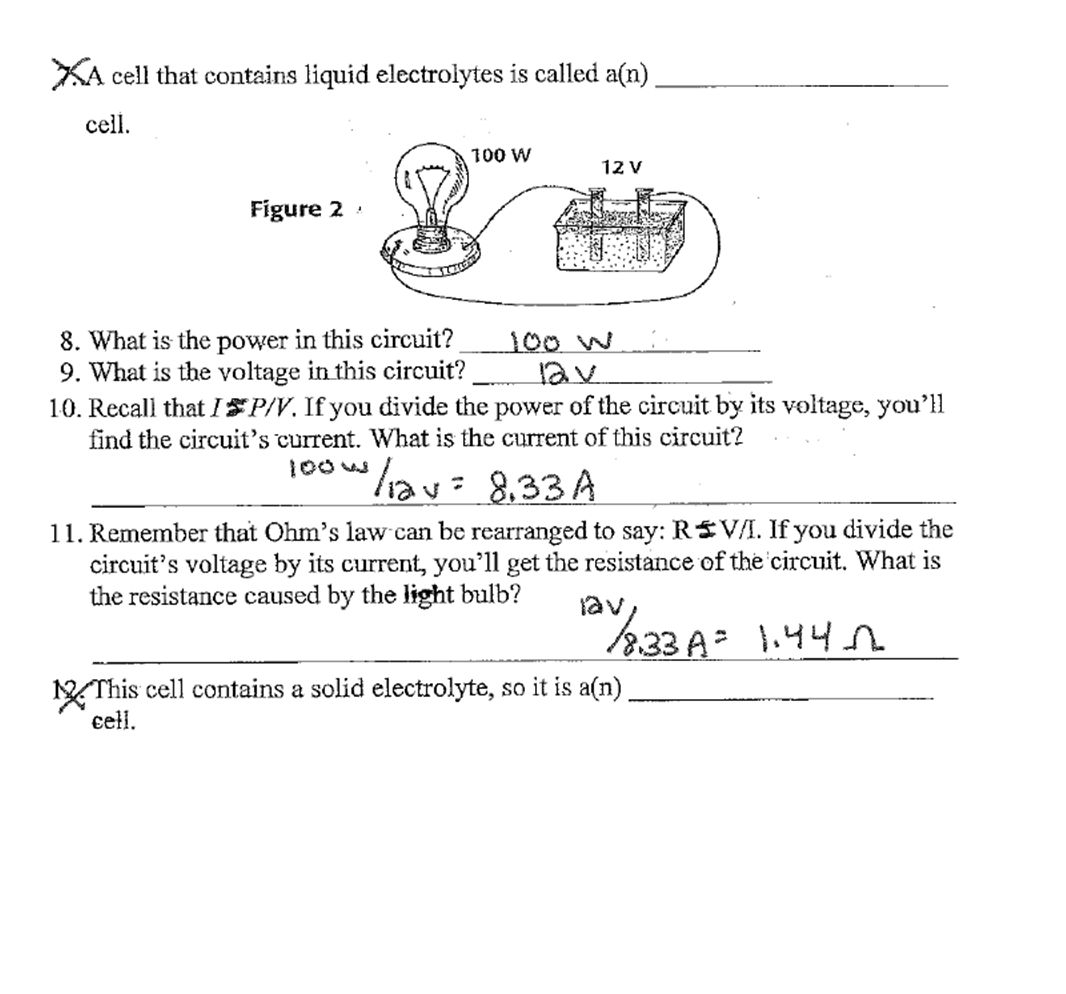
Chapter Review U SING KEY TERMS T he statements below are false. For each statement, replace the underlined term to make a true statement. 1.Charges flow easily in an electrical insulator. 2.Lightning is a form of static electricity. 3.A thermocouple converts chemical energy into electrical energy. 4.Voltage is the opposition to the current by a material. 5.Electric force is the rate at which electrical energy is converted into other forms of energy. 6.Each load in a parallel circuit has the same current.

105
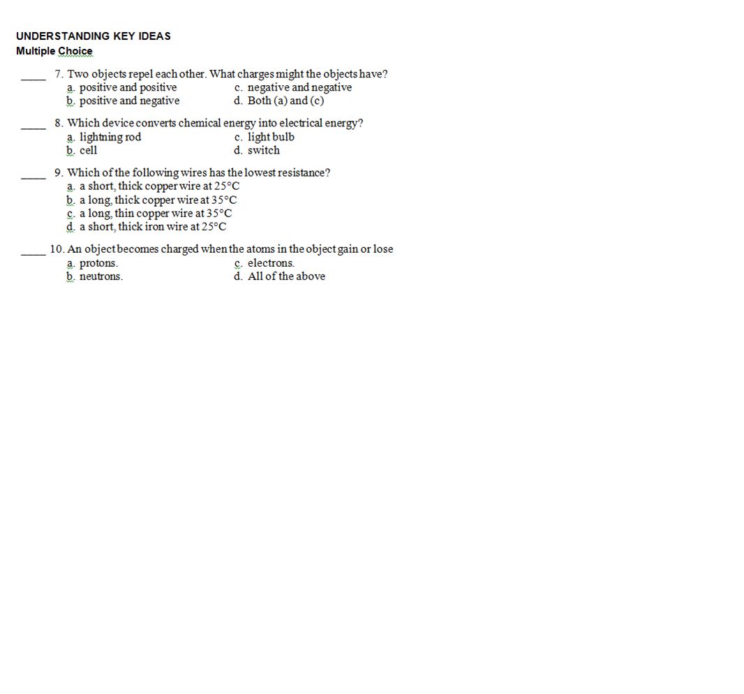
Chapter Review 1.electrical conductor 2.electric discharge 3.cell 4.Resistance 5.Electric power 6.series circuit 7.D 8.B 9.A 10.C 11.A 12.A 13.B

106
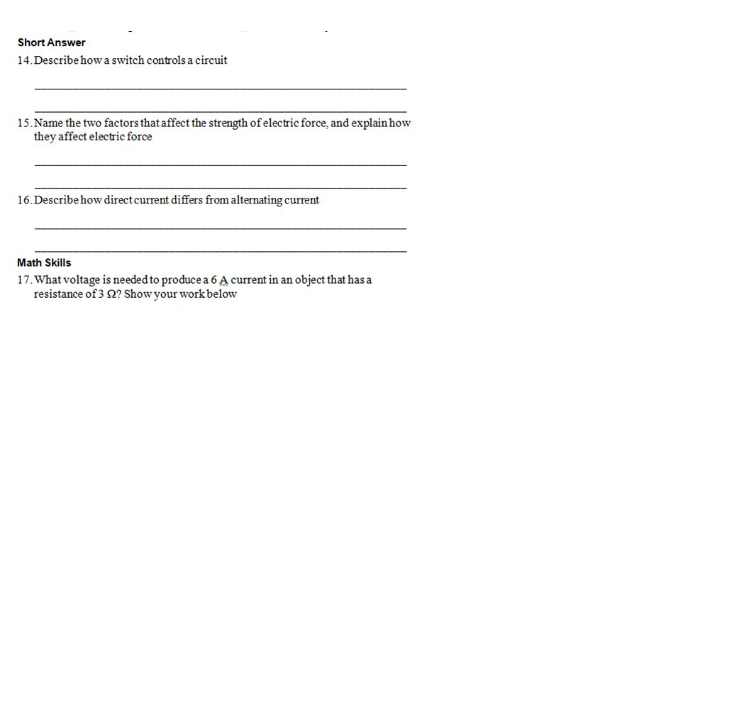
14.When a switch is open, it creates a break in the circuit. Charges cannot flow in the circuit. When a switch is closed, it closes the gap in the circuit. The circuit is complete, so charges can flow in it. 15.One factor is the amount of the electric charge. The greater the charge is, the greater the force. The other factor is the distance between the charges. The closer the charges are to each other, the greater the force between them 16.The charges in direct current flow in one direction. In alternating current, the charges continually switch from flowing in one direction to flowing in the reverse direction

107
17.V I R 6 A 3 18 V 18.I V/R 60 V/15 4 A 19.R V/I 40 V/5 A 8 9E 20.I P/V 150 W/120 V 1.25 A

108
21.E P t 0.06 kW 1,000 h 60 kWh 22.An answer to this exercise can be found at the end of the Teacher Edition. 23.The electrician must have wired the fish-tank bubbler in series with the lights and the computer in series with the overhead projector 24.You would push the strip of copper and the strip of silver into the apple. The apple is the electrolyte, and the metal strips are the electrodes. Students may identify the cell as a dry cell because the apple is a solid or as a wet cell because the apple juice conducts the electric current.

109
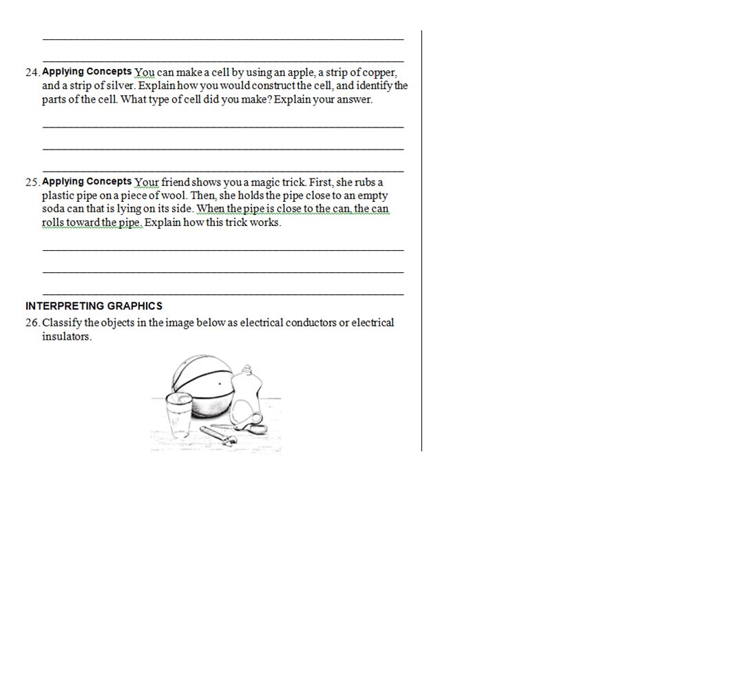
25.When the pipe is rubbed with a piece of wool, the pipe is charged by friction. When the charged pipe is held close to the can, the charges in the can are rearranged and the can is charged by induction. The side of the can closest to the pipe has the opposite charge that the pipe has, and the can is attracted to the pipe. 26.conductors: tap water in glass, wrench, metal part of scissors, liquid soap in plastic bottle; insulators: basketball, glass, plastic bottle, plastic scissors handles, wooden table

Similar presentations


 to battery/batteries correctly?>")


 Electrons (-) Neutrons (0)>")


 electrons.>")


 Negative More.>")

 on an object opposite charges attract, like charges repel There are 3.>")
