Download presentation
Presentation is loading. Please wait.

3
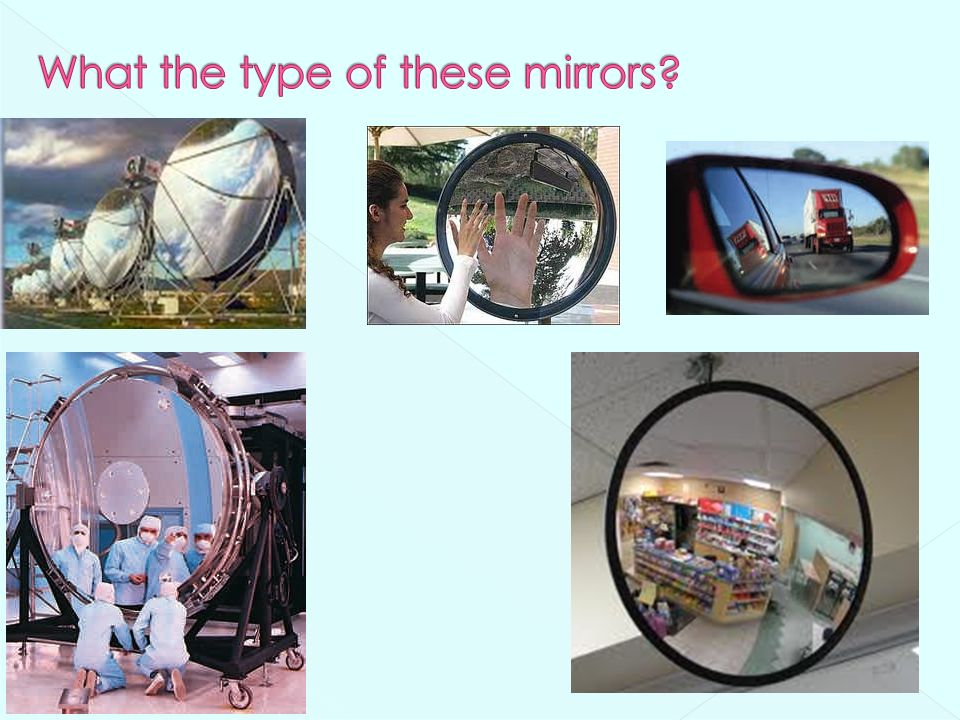
Basics Reflection Mirrors Plane mirrors Spherical mirrors Concave mirrors Convex mirrors Refraction Lenses Concave lenses Convex lenses

5
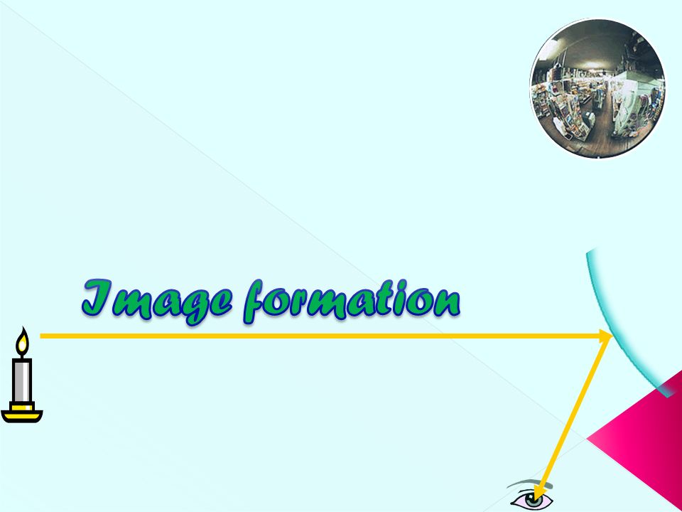
All visible objects emit or reflect light rays in all directions. Everything that can be seen is seen only when light from that object travels to our eyes. Whether it be a luminous object (that generates light of its own) or an illuminated object (that reflects the light that is incident upon it)
 or an illuminated object (that reflects the light that is incident upon it).")
6
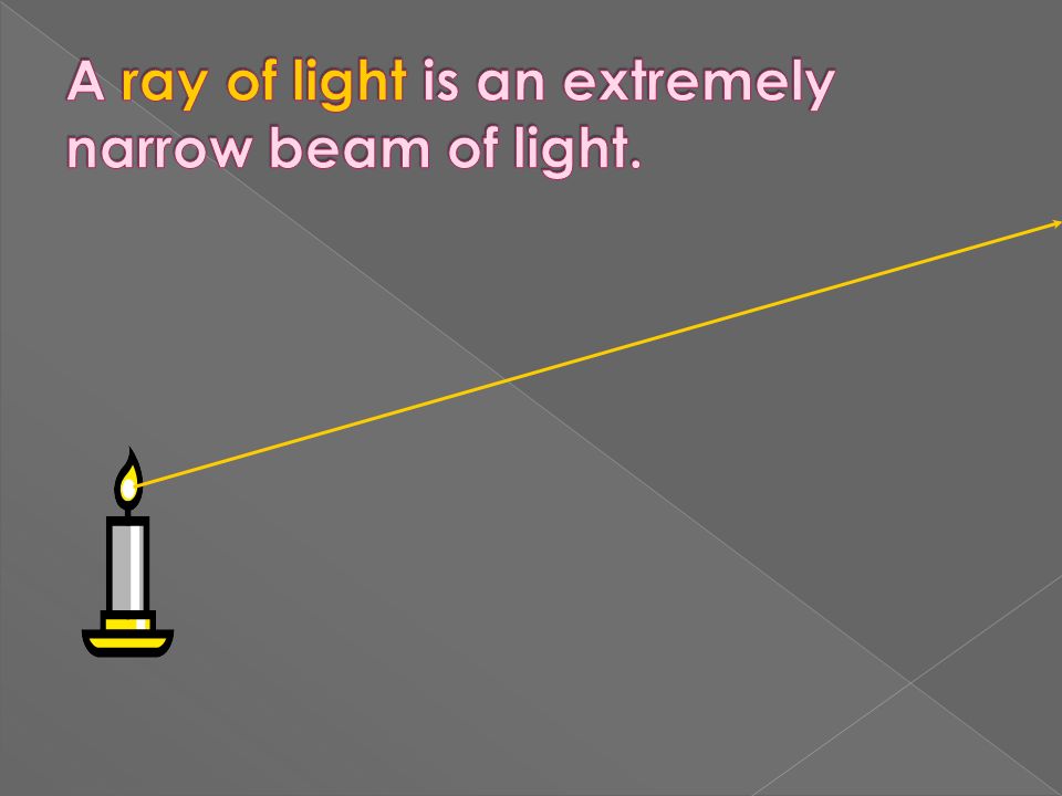
Our eyes detect light rays.

7
We think we see objects. We really see images. In order to view an object, you must sight along a line at that object; and when you do light will come from that object to your eye along the line of sight.

8
converge: come together Images are formed when light rays converge.

9
When light rays go straight into our eyes, we see an image in the same spot as the object. object & image

10
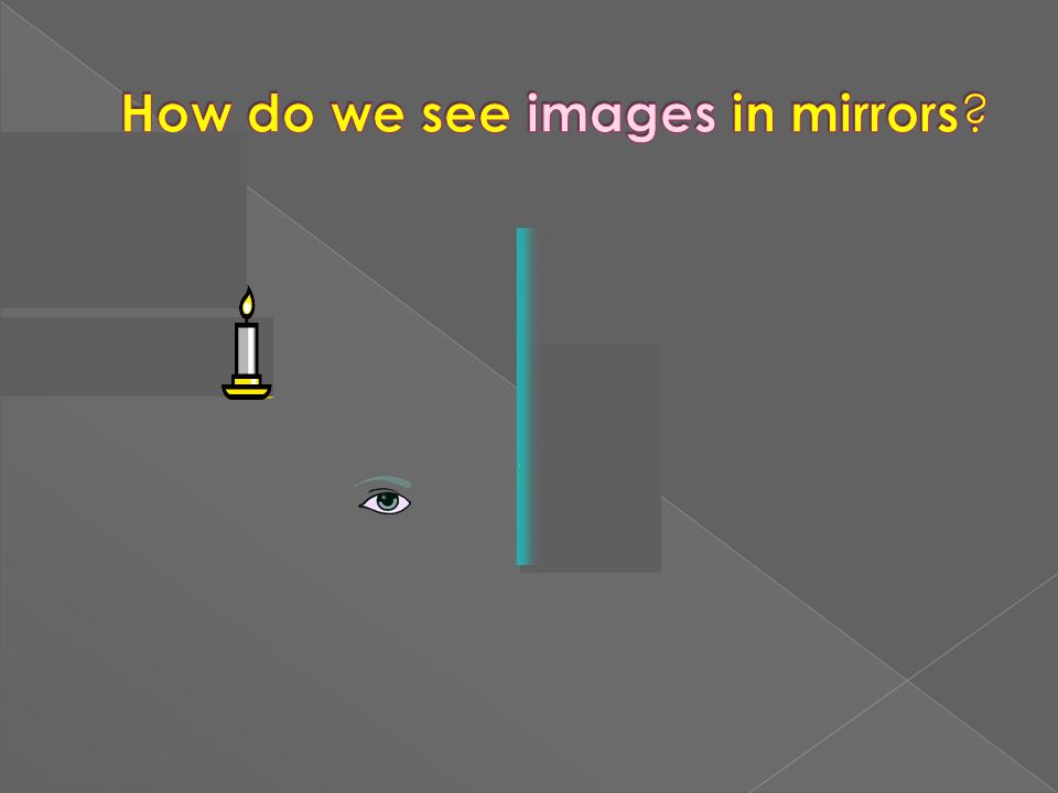
Mirrors reflect light rays.

12
objectimage Light from the object reflects off the mirror and converges to form an image.

13
objectimage We perceive all light rays as if they come straight from an object. The imaginary light rays that we think we see are called sight lines.

14
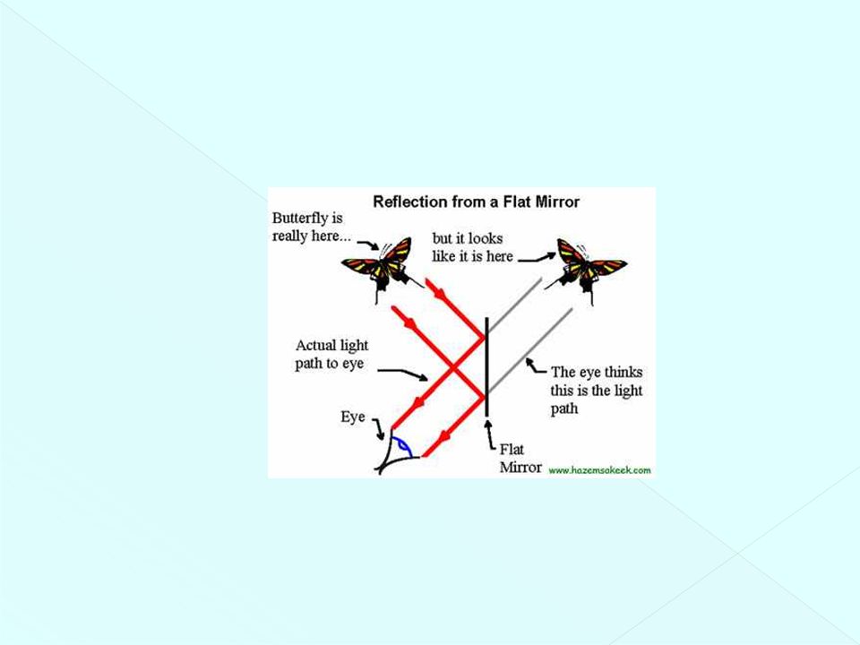
objectimage Real images are formed by light rays. Virtual images are formed by sight lines. mirror object & image window

16
Images can result when light rays encounter flat or curved surfaces between two media. Images can be formed either by reflection or refraction due to these surfaces. Mirrors and lenses can be designed to form images with desired characteristics. The object distance is the distance from the object to the mirror or lens. › Denoted by p The image distance is the distance from the image to the mirror or lens. › Denoted by q The lateral magnification of the mirror or lens is the ratio of the image height to the object height. › Denoted by M

17
Images are always located by extending diverging rays back to a point at which they intersect. Images are located either at a point from which the rays of light actually diverge or at a point from which they appear to diverge. A real image is formed when light rays pass through and diverge from the image point. › Real images can be displayed on screens. A virtual image is formed when light rays do not pass through the image point but only appear to diverge from that point. › Virtual images cannot be displayed on screens.

18
Simplest possible mirror. Light rays leave the source and are reflected from the mirror. imag Point I is called the image of the object at point O. The image is virtual. No light ray from the object can exist behind the mirror, so the light rays in front of the mirror only seem to be diverging from I. virtual image A flat mirror always produces a virtual image. Geometry can be used to determine the properties of the image. There are an infinite number of choices of direction in which light rays could leave each point on the object. Two rays are needed to determine where an image is formed.

19
One ray starts at point P, travels to Q and reflects back on itself. Another ray follows the path PR and reflects according to the law of reflection. The triangles PQR and P’QR are congruent. To observe the image, the observer would trace back the two reflected rays to P’. Point P’ is the point where the rays appear to have originated. The image formed by an object placed in front of a flat mirror is as far behind the mirror as the object is in front of the mirror. › |p| = |q|

21
Lateral magnification, M, is defined as › This is the lateral magnification for any type of mirror. › It is also valid for images formed by lenses. › Magnification does not always mean bigger, the size can either increase or decrease. M can be less than or greater than 1. The lateral magnification of a flat mirror is +1. This means that h’ = h for all images. The positive sign indicates the object is upright. › Same orientation as the object

22
A flat mirror produces an image that has an apparent left-right reversal. › For example, if you raise your right hand the image you see raises its left hand. The reversal is not actually a left-right reversal. The reversal is actually a front-back reversal. › It is caused by the light rays going forward toward the mirror and then reflecting back from it.

23
The image is as far behind the mirror as the object is in front. › |p| = |q| The image is unmagnified. › The image height is the same as the object height. h’ = h and M = +1 The image is virtual. The image is upright. › It has the same orientation as the object. There is a front-back reversal in the image.

24
With the daytime setting, the bright beam (B) of reflected light is directed into the driver’s eyes. With the nighttime setting, the dim beam (D) of reflected light is directed into the driver’s eyes, while the bright beam goes elsewhere.
 of reflected light is directed into the driver’s eyes, while the bright beam goes elsewhere..")
25
In what location will the image form? 1. A 2. B 3. C 4. D In what location will the image form? 1. A 2. B 3. C 4. D

27
A spherical mirror has the shape of a section of a sphere. The mirror focuses incoming parallel rays to a point. A concave spherical mirror has the silvered surface of the mirror on the inner, or concave, side of the curve. A convex spherical mirror has the silvered surface of the mirror on the outer, or convex, side of the curve.

28
radius of curvature of R. The mirror has a radius of curvature of R. center of curvature is the point C Its center of curvature is the point C V the center of the spherical segment. Point V is the center of the spherical segment. principal axis of the mirror. A line drawn from C to V is called the principal axis of the mirror. The blue band represents the structural support for the silvered surface.

29
We use only rays that diverge from the object and make a small angle with the principal axis. Such rays are called paraxial rays. All paraxial rays reflect through the image point.

30
Distances are measured from V Geometry can be used to determine the magnification of the image. › h’ is negative when the image is inverted with respect to the object. Geometry also shows the relationship between the image and object distances. › This is called the mirror equation. If p is much greater than R, then the image point is half-way between the center of curvature and the center point of the mirror. › p → ∞, then 1/p 0 and q R/2

31
When the object is very far away, then p → ∞ and the incoming rays are essentially parallel. In this special case, the image point is called the focal point. The distance from the mirror to the focal point is called the focal length. › The focal length is ½ the radius of curvature. The colored beams are traveling parallel to the principal axis. The mirror reflects all three beams to the focal point. The focal point is where all the beams intersect. › The colors add to white.

32
The focal point is dependent solely on the curvature of the mirror, not on the location of the object. › It also does not depend on the material from which the mirror is made. Since the focal length is related to the radius of curvature by ƒ = R / 2, the mirror equation can be expressed as

33
optical axis F Light rays that come in parallel to the optical axis reflect through the focal point.

34
Rays: 1) A ray which is parallel to the principle axis will reflect through the focal point. 2) A ray which passes through the focal point will reflect parallel to the principle axis. 3) A ray through the center of curvature will reflect back on itself Drawing ray diagrams for spherical mirror and plane mirror reflections
 A ray which passes through the focal point will reflect parallel to the principle axis. 3) A ray through the center of curvature will reflect back on itself Drawing ray diagrams for spherical mirror and plane mirror reflections.")
35
optical axis F The first ray comes in parallel to the optical axis and reflects through the focal point.

36
principle axis F The first ray comes in parallel to the optical axis and reflects through the focal point. The second ray comes through the focal point and reflects parallel to the optical axis.

37
optical axis F The first ray comes in parallel to the optical axis and reflects through the focal point. The second ray comes through the focal point and reflects parallel to the optical axis. A real image forms where the light rays converge.

38
principle axis F

39
optical axis F The first ray comes in parallel to the optical axis and reflects through the focal point.

40
optical axis F The first ray comes in parallel to the optical axis and reflects through the focal point. The second ray comes through the focal point and reflects parallel to the optical axis.

41
optical axis F The first ray comes in parallel to the optical axis and reflects through the focal point. The second ray comes through the focal point and reflects parallel to the optical axis. The image forms where the rays converge. But they don’t seem to converge.

42
optical axis F The first ray comes in parallel to the optical axis and reflects through the focal point. The second ray comes through the focal point and reflects parallel to the optical axis. A virtual image forms where the sight rays converge.

43
The object is between the mirror surface and the focal point. The image is virtual. The image is upright. The image is larger than the object (enlarged). The center of curvature is between the object and the concave mirror surface. The image is real. The image is inverted. The image is smaller than the object (reduced).
. The center of curvature is between the object and the concave mirror surface. The image is real. The image is inverted. The image is smaller than the object (reduced)..")
44
These sign conventions apply to both concave and convex mirrors. The equations used for the concave mirror also apply to the convex mirror. Be sure to use proper sign choices when substituting values into the equations.

45
With a concave mirror, the image may be either real or virtual. › When the object is outside the focal point, the image is real. › When the object is at the focal point, the image is infinitely far away. › When the object is between the mirror and the focal point, the image is virtual. With a convex mirror, the image is always virtual and upright. › As the object distance decreases, the virtual image increases in size. Section 36.2

47
Light rays that come in parallel to the optical axis reflect from the focal point. optical axis F The focal point is considered virtual since sight lines, not light rays, go through it.

48
Ray 1 is drawn from the top of the object parallel to the principal axis and is reflected away from the focal point, F. Ray 2 is drawn from the top of the object toward the focal point and is reflected parallel to the principal axis. Ray 3 is drawn through the center of curvature, C, on the back side of the mirror and is reflected back on itself.

49
optical axis F The first ray comes in parallel to the optical axis and reflects through the focal point.

50
optical axis F The first ray comes in parallel to the optical axis and reflects through the focal point. The second ray comes through the focal point and reflects parallel to the optical axis.

51
optical axis F The first ray comes in parallel to the optical axis and reflects through the focal point. The second ray comes through the focal point and reflects parallel to the optical axis. The light rays don’t converge, but the sight lines do.

52
optical axis F The first ray comes in parallel to the optical axis and reflects through the focal point. The second ray comes through the focal point and reflects parallel to the optical axis. The light rays don’t converge, but the sight lines do. A virtual image forms where the sight lines converge.

53
The object is between the mirror surface and the focal point. The image is virtual. The image is upright. The image is larger than the object (enlarged).
..")
54
ƒ = focal length d o = object distance d i = image distance f is negative for diverging mirrors and lenses d i is negative when the image is behind the lens or mirror

55
m = magnification h i = image height h o = object height If height is negative the image is upside down if the magnification is negative the image is inverted (upside down)
")
56
Which ray is correct? ray A ray B ray C ray D

59
The first telescope, designed and built by Galileo, used lenses to focus light from faraway objects, into Galileo’s eye. His telescope consisted of a concave lens and a convex lens. Light rays are always refracted (bent) towards the thickest part of the lens. convex lens concave lens light from far away object
 towards the thickest part of the lens. convex lens concave lens light from far away object.")
60
Concave lenses are thin in the middle and make light rays diverge (spread out). If the rays of light are traced back ( dotted sight lines ), they all intersect at the focal point (F) behind the lens. optical axis F
, they all intersect at the focal point (F) behind the lens. optical axis F.")
61
F Light rays that come in parallel to the optical axis diverge from the focal point. The light rays behave the same way if we ignore the thickness of the lens.

62
optical axis F Light rays that come in parallel to the optical axis still diverge from the focal point.

63
The first ray comes in parallel to the optical axis and refracts from the focal point. optical axis F

64
F The first ray comes in parallel to the optical axis and refracts from the focal point. The second ray goes straight through the center of the lens.

65
optical axis F The first ray comes in parallel to the optical axis and refracts from the focal point. The second ray goes straight through the center of the lens. The light rays don’t converge, but the sight lines do.

66
optical axis F The first ray comes in parallel to the optical axis and refracts from the focal point. The second ray goes straight through the center of the lens. The light rays don’t converge, but the sight lines do. A virtual image forms where the sight lines converge.

67
Convex lenses are thicker in the middle and focus light rays to a focal point in front of the lens. The focal length of the lens is the distance between the center of the lens and the point where the light rays are focused.

68
Convex lenses are thicker in the middle and focus light rays to a focal point in front of the lens. The focal length of the lens is the distance between the center of the lens and the point where the light rays are focused.

69
optical axis F F

70
Light rays that come in parallel to the optical axis converge at the focal point. F

71
F The first ray comes in parallel to the optical axis and refracts through the focal point. optical axis

72
F The first ray comes in parallel to the optical axis and refracts through the focal point. optical axis

73
F The first ray comes in parallel to the optical axis and refracts through the focal point. The second ray goes straight through the center of the lens. optical axis

74
F The first ray comes in parallel to the optical axis and refracts through the focal point. The second ray goes straight through the center of the lens. The light rays don’t converge, but the sight lines do. O I

75
Figure 1: Image formation in a camera Figure 2: Image formation with a projector

77
As you look at Mary in class, you are able to see Mary because she is illuminated with light and that light reflects off of her and travels to your eye. In the process of viewing Mary, you are directing your sight along a line in the direction of Mary. If you wish to view the top of Mary's head, then you direct your sight along a line towards the top of her head. If you wish to view Mary's feet, then you direct your sight along a line towards Mary's feet. And if you wish to view the image of Mary in a mirror, then you must direct your sight along a line towards the location of Mary's image. This directing of our sight in a specific direction is sometimes referred to as the line of sight. It is common to observe this law. To view an image of a pencil in a mirror, you must sight along a line at the image location. As you sight at the image, light travels to your eye along the path shown in the diagram below. The diagram shows that the light reflects off the mirror in such a manner that the angle of incidence is equal to the angle of reflection.

78
Rays that are far from the principal axis converge to other points on the principal axis. › The light rays make large angles with the principal axis. This produces a blurred image. The effect is called spherical aberration.

Similar presentations