Download presentation
Presentation is loading. Please wait.

1
Connecting Low Carbon Generation Clive Goodman Primary System Design Engineer

2
Western Power Distribution Wholly owned subsidiary Pennsylvania Power & Light ( PPL) 4 UK Distribution Licences incl. former CN since April 1 st 2011 Serves 7.6 million homes + businesses 55,000 sq km Largest length UK network – roughly 1/3

3
Renewable Generation Wind Photovoltaic Hydro Wave Biomass Geothermal Other?

4
Growth of Distributed Generation 240% increase in DG connection (2009/10) Ofgem Feed-in-Tariffs were introduced on 1 April 2010 & provide incentives for small-scale generators to to 5MW
 Ofgem Feed-in-Tariffs were introduced on 1 April 2010 & provide incentives for small-scale generators to to 5MW")
5
What is Driving Distributed Generation ? Environmental Concerns – Greenhouse Gas Emissions from Fossil Fuels Technological Innovation- Wind, Wave, Solar & Biofuels New Government Policy – Secure, Low Carbon, Competitively Priced

6
Feed in Tariffs (FITS) Introduced on 1 April 2010 Provide financial incentives for small-scale generators up to 5MW Most installations are Photovoltaic and Wind South West & South East accounting for almost 40% of the total installations Total Installed Capacity Breakdown of FIT installations by technology: 81 % Photovoltacic 11% Wind 5% Hydro 3% Anaerobic digestion
 Introduced on 1 April 2010 Provide financial incentives for small-scale generators up to 5MW Most installations are Photovoltaic and Wind South West & South East accounting for almost 40% of the total installations Total Installed Capacity Breakdown of FIT installations by technology: 81 % Photovoltacic 11% Wind 5% Hydro 3% Anaerobic digestion")
7
Renewable Resource

8
Small Scale Embedded Generation (SSEG) Low Voltage 230/400V Up to and including 16A per phase, single or multiple phase 3.68kW (Single-Phase) 11.04kw (Three-Phase)
 Low Voltage 230/400V Up to and including 16A per phase, single or multiple phase 3.68kW (Single-Phase) 11.04kw (Three-Phase)")
9
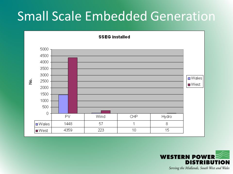
Small Scale Embedded Generation

11
Utilities Act 2000 It shall be the duty of an electricity distributor – (a)To develop and maintain an efficient, co- ordinated and economical system of electricity distribution (b)To facilitate competition in the supply and generation of electricity
To develop and maintain an efficient, co- ordinated and economical system of electricity distribution (b)To facilitate competition in the supply and generation of electricity")
12
Connection Process G83 Stage 1 – Single Installations of SSEG – Legal Obligation for installers to notify the DNO within 28 days of commissioning G83 Stage 2 – Multiple Installations of SSEG (eg. Housing refurbishment in the same street or New Housing Development)– Application to the DNO required + test certification. Application considered and costs/implications advised G59 – Larger applications for generators in excess of 16A per phase (3.68KW)
– Application to the DNO required + test certification. Application considered and costs/implications advised G59 – Larger applications for generators in excess of 16A per phase (3.68KW).")
13
Electricity Network Challenges Reverse Power Flow Voltage Rise Equipment Ratings Power Quality Voltage Disturbances (flicker) Voltage Distortion (harmonics) Fault Levels Equipment short circuit ratings
 Voltage Distortion (harmonics) Fault Levels Equipment short circuit ratings")
14
Traditional Network Power Flow

15
Renewable Generation Reverse Power Flow Power Flow

16
Voltage Rise Theory Assumes lightly loaded Voltage rise pu = V1 -Vo

17
Voltage Rise Ohms Law V = I x R

18
Voltage Rise Solutions: Reduce resistance (impedance) of the network. Improve network utilisation (i.e. ensure we get the most out of the network) Limit the connection of generation
 Limit the connection of generation.")
19
Voltage Rise Improve Network Utilisation: Improve network modelling Increase monitoring on the LV network (Smart Meters and Smart Networks) Improve voltage regulation at 132kV and 33kV substations Reduce voltage on HV and LV networks Introduce load / generator control Introduce automatic voltage regulation on our LV networks
 Improve voltage regulation at 132kV and 33kV substations Reduce voltage on HV and LV networks Introduce load / generator control Introduce automatic voltage regulation on our LV networks")
20
Power Quality Voltage Disturbance: Sudden increase or reduction in current / power causing voltage to dip or rise Causes flickering lights Solutions: Improve equipment design Reduce resistance (impedance) of the network Changes in lighting technology may help (e.g. compact fluorescent lighting)
.")
21
Power Quality Voltage Distortion (harmonics): Caused by non-linear load / generation (power electronics, inverters, motor drives, fluorescent lighting etc.) High levels of harmonics can cause capacitors / power supplies to fail, transformers to overheat, cables to overheat and metering inaccuracy Solutions: Improve equipment design Reduce resistance (impedance) of the network
: Caused by non-linear load / generation (power electronics, inverters, motor drives, fluorescent lighting etc.) High levels of harmonics can cause capacitors / power supplies to fail, transformers to overheat, cables to overheat and metering inaccuracy Solutions: Improve equipment design Reduce resistance (impedance) of the network")
22
Low Carbon Networks Fund £500 Million Funding Tier 1 £80 Million for small scales projects across all the DNOs Tier 2 £320 Million for ‘Flagship Projects’ where DNOs compete for funding £100 Million discretionary fund Accelerate development of Low Carbon Electricity System Impact on DNO network performance Delivered benefits to customers expected to exceed cost of project Generate new knowledge to be shared

23
Low Carbon Networks Fund WPD Projects Include: Network Templates Project (monitoring 1000 distribution substations and associated LV network) Melin Homes - 20 PV installations (38kW) 11kV Voltage Regulation (use of STATCOM systems)
 Melin Homes - 20 PV installations (38kW) 11kV Voltage Regulation (use of STATCOM systems)")
24
Low Carbon Network Fund Tier 2 Projects 2011 FALCON (Western Power Distribution East Midlands) Facilitate the installation of low carbon technologies by avoiding traditional reinforcement Use of real time network data in inform network decisions Development of a scenario investment model using data from the trials Control network tests in an area with about 200 distribution and primary substations centred on Milton Keynes
 Facilitate the installation of low carbon technologies by avoiding traditional reinforcement Use of real time network data in inform network decisions Development of a scenario investment model using data from the trials Control network tests in an area with about 200 distribution and primary substations centred on Milton Keynes")
25
Low Carbon Networks Tier 2 Projects 2011 Buildings, Renewables, Integrated Storage To Overcome Limitations (BRISTOL) 30 Houses, 10 Schools and an Office with Solar PV and Battery installation Solar PV Battery connected using DC connection DC Lighting Circuits + Small appliances run on DC direct from solar PV and battery Battery ‘shared’ between Customer and DNO Tariff to encourage electricity use at times of high PV generation and use battery when network is heavily loaded Focused on social housing in Bristol in conjunction with Bristol City Council Solar PV, Heat Pumps & Electric Vehicles require network reinforcement – Project will provide data on how the existing capacity may be better utilised
 30 Houses, 10 Schools and an Office with Solar PV and Battery installation Solar PV Battery connected using DC connection DC Lighting Circuits + Small appliances run on DC direct from solar PV and battery Battery ‘shared’ between Customer and DNO Tariff to encourage electricity use at times of high PV generation and use battery when network is heavily loaded Focused on social housing in Bristol in conjunction with Bristol City Council Solar PV, Heat Pumps & Electric Vehicles require network reinforcement – Project will provide data on how the existing capacity may be better utilised")
26
The End

Similar presentations


 Update ENA 2012 Low Carbon Network Fund Conference 26 October 2012.>")


 Venkata Alstom Grid and University of Washington (UW)>")

>")

