Download presentation
Presentation is loading. Please wait.

1
EXCAVATION & TRENCHING AWARENESS FOR THE CONSTRUCTION INDUSTRY

2
OSHA Susan Harwood Grant
This material was produced under grant number SH F24 from the Occupational Safety and Health Administration, U.S. Department of Labor. It does not necessarily reflect the views or policies of the U.S. Department of Labor, nor does mention of trade names, commercial products or organizations imply endorsement by the U.S. Government

3
EXCAVATION & TRENCHING AWARENESS FOR THE CONSTRUCTION INDUSTRY

4
Maryland Fire & Rescue Institute
Compliance training over 35 years Consulting Services Six (6) MFRI sites throughout Maryland Training at Clients Sites Hands - on instruction
 MFRI sites throughout Maryland. Training at Clients Sites. Hands - on instruction.")
5
Pre - Test Cave – ins can happen without warning
True or False A hazardous atmosphere can be found in a trench

6
Pre - Test A protective system is a method of protecting employees from cave-ins True or False A ladder shall be used for access and egress in trenches ___ ft or greater in depth 10, 25, 4, 16

7
Pre - Test A competent person must be aware of: Access and egress
Water accumulating Hazardous atmosphere All the above

8
Pre - Test Soil classifications are; A, B, C, Stable rock 1, 2, 3, 4
Rocky or Smooth Hard or Soft

9
Pre - Test The testing of soil consists of a ___ and a ___ test.
Day, Night Summer, winter Visual, manual Hot, cold

10
Pre - Test If water is added to soil it brings; Lunch
Additional weight Strength

11
Pre - Test What effects on the body can a cave-in cause;
Respiratory distress Crush syndrome Total body impact All the above

12
Pre - Test Soil can weigh about ___ lbs a cubic foot; 125 400 600 50

13
Pre - Test Factors that influence cave-ins are; Intersecting trenches
Previously disturbed soil Vibration All the above

14
Pre - Test The excavation standard also applies to trenches
True or False Benching is a method of protecting employees from cave-ins;

15
Pre - Test A trench box should be used to protect employees;
True or False No employee shall be permitted underneath loads handled by lifting or digging equipment

16
Enabling Objectives Identify the laws, regulations, and standards as they apply to excavations Describe soil classification and the testing used to determine type Describe protective systems used in excavations Discuss the hazards found in trenches Describe the role of the competent person

17
Overview / Main Points Excavation laws, regulations, standards
Soil classification Soil testing Competent person responsibilities Hazards associated with trenches Protective systems

18
Man buried up to the waist
Man buried up to the waist. 3 hours to extricate, minor crush syndrome, widest part of trench is 18 inches at top

19
Stuck to mid thigh in Prince George’s County Md
Stuck to mid thigh in Prince George’s County Md. Compound fracture of right leg, 2 hrs to extricate, Latin immigrant speaks no English.

20
Do not let operators use machines to extricate victims

21
Lock out/ tag out? Dive team made rescue

22
Tragic Facts Excavating is recognized as one of the most hazardous construction operations 541 Workers were killed on Excavation/Trenching jobs from 411 (76%) were killed by cave-ins 257 (47%) worked for companies employing less than 10 people
 were killed by cave-ins. 257 (47%) worked for companies employing less than 10 people.")
23
Tragic Facts 60% are would be rescuers
Civilians Fire dept personnel Co-workers Cave-ins can happen without warning All of the fatalities and injuries could have been prevented

24
Collapse Forces 24 inches of soil on a person’s chest weighs
lb. 18 inches of soil covering a body weighs lb. HOW MUCH CAN YOU LIFT, how well can you breathe HOW MANY BREATHS CAN YOU TAKE LOCK OUT/ TAG OUT 8” WATER MAIN CAN FLOW 19,000 GPM AT 100 PSI CAN FILL A TRENCH 4X12X25 IN 24 SECONDS

25
Soil Weight Example © ACR Publications Used By Permission

26
Collapse Forces Shear wall collapse speed 45 mph
1 cubic foot of soil can weigh from 100 to 125 lb. THINK YOU CAN OUT RUN IT VW HITTING YOU AT 45MPH PAST PRACTICES JUMP INTO TRENCH F/F ARE ACTION ORIENTED COMPASSION KILLS INADEQUATE SHORING CHEAPER TO PAY DEATH BENEFITS

27
Speed of Collapsing Dirt
Imagine this coming down on top of you…. Weight of a Volkswagen Weight of one cubic yard of soil 2,785 Pounds 2,700 Pounds

28
Effects On The Body Respiratory distress Crush syndrome
Total body impact How many breaths can you take with this much weight on your body, explain crush syndrome

29
If dirt can do this to a ladder?

30
The Top Five Trenching Hazards
Cave – ins Overhead Electric Line Contact Falls into Excavations Equipment Falling into Excavations Explosion / Fire / Electrocution

31
UNSAFE ATTITUDES “I Know what I’m doing.” “It can’t happen to me.”
“I’ve been doing it that way for years.” “I’d sleep in that hole!” “Don’t worry, we’ll watch the walls and tell you if you need to get out.”

32
Most Common Causes of Cave-ins:
Poor Planning Misjudgment of soil type. Inadequate, or incorrect installation of protective devices. Defective protective devices. Failure to adjust for changing conditions

33
Legal Aspects OSHA [29 CFR 1926.650 - 652]
Excavation standard applies to all open excavations made in the earth’s surfaces including trenches, all surface encumbrances that would create a hazard, and protective systems
![Legal Aspects OSHA [29 CFR ]](http://slideplayer.com/slide/4285713/14/images/33/Legal+Aspects+OSHA+%5B29+CFR+%5D.jpg "Excavation standard applies to all open excavations made in the earth’s surfaces including trenches, all surface encumbrances that would create a hazard, and protective systems.")
34
What’s In the Standard? scope, application and definitions
Job Site Hazard Listing Requirements for Protective Systems Appendixes that detail: Soil Classification Sloping and Benching Timber and Aluminum Hydraulic Shoring Protective System Selection Decision Tree

35
Definitions 1926.650 Accepted engineering practices
Aluminum hydraulic shoring Bell-bottom pier hole Benching Cave-in Cross braces Excavation Faces or Sides Failure Hazardous Atmosphere Kickout Protective system Ramp Registered Professional Engineer Sheeting Shield

36
Definitions Shoring Sloping Stable rock Structural ramp
Support systems Tabulated data Trench Uprights Wales

37
General Requirements 1926.651 (a) Surface encumbrances
(b) Underground installations (c) Access & egress (d) Exposure to vehicle traffic (e) Exposure to falling loads (f) Warning systems for mobile equipment
 Underground installations. (c) Access & egress. (d) Exposure to vehicle traffic. (e) Exposure to falling loads. (f) Warning systems for mobile equipment.")
38
General Requirements 1926.651 (g) Hazardous atmospheres
(h) Protection from hazards associated with water accumulation (i) Stability of adjacent structures (j) Protection from loose rock or soil (k) Inspections (l) Fall protection
 Protection from hazards associated with water accumulation. (i) Stability of adjacent structures. (j) Protection from loose rock or soil. (k) Inspections. (l) Fall protection.")
39
Surface Encumbrances All surfaces encumbrances that are located so as to create a hazard to employees shall be removed or supported as necessary to safeguard employees

40
Underground Installations
Utility companies shall be contacted with in established local response times Advised of proposed work Asked to establish location of utility When request cannot be met, employer may proceed with caution with detection equipment of an acceptable means to locate utility Call before you dig: In Maryland and Delaware Dial 811

41
Underground Installations
While the excavation is open, underground installations shall be protected, supported or removed as necessary to safeguard employees

42
Access & Egress Structural ramps
Used by employees shall be designed by a competent person When used for equipment shall be designed competent person qualified in structural design Stairway, ladder, ramp or other safe means of egress require no more than 25 ft of lateral travel for employees in excavations that are 4 feet or more in depth Ladders must be secured and extend a minimum of 36 inches above the landing

43
Exposure to vehicle traffic
Employees exposed to public vehicle traffic shall be provided with and wear warning vests or other suitable garments Marked or made with reflectorized or highly visible material Requiring a designated, trained flag person along with signs, signals, and barricades when necessary

44
Exposure to falling loads
No employee shall be permitted underneath loads handled by digging or lifting equipment Stand away from vehicle being loaded or unloaded to avoid being struck Operators may remain in cabs when vehicles are equipped in accordance with

45
Victim was working underneath load being moved

46
Warning systems for mobile equipment
When operator does not have clear view of edge of excavation Warning system shall be utilized Barricades Hand or mechanical signals Stop logs

47
Victim was ejected from tractor into the trench (lower center )
")
48
How much vibration does a concrete truck put on the side of a trench when mixing his load. Enough to cause collapse?

49
Hazardous Atmospheres
Testing and controls To prevent harmful levels of atmospheric contaminants Less than 19.5% or more than 23.5% oxygen Atmosphere tested before entry Adequate precautions shall be taken Ventilation Proper respiratory protection Testing done often as necessary TEST IN MULTIPLE LEVELS – TOP/MIDDLE/BOTTOM ( SAME AS CONFINED SPACE)
")
50
Unshored trench with backhoe and track hoe on lip with trash pump for water removal

51
Worker using a cut-off saw, gas can also in excavation

52
Monitoring Monitoring for hazardous atmospheres

53
Ventilation Blowers Propane system for heated ventilation

54
Emergency Rescue Equipment
Breathing equipment Safety harness and line or basket stretcher Must be readily available Must be attended Bell-bottom pier holes, deep and confined footing excavation shall wear a harness with a lifeline securely attached to it

55
Water Accumulation How much water is to much?

56
Water Accumulation Employees shall not work in excavations where there is accumulated water, or where water is accumulating, unless adequate precautions have been taken, to protect employees.

57
Water Accumulation Must take adequate precautions to protect employees
Accumulating water Varies with each situation Removal monitored by competent person Run off from heavy rains requires inspection by competent person

58
Well point system to lower ground water, pipes placed in ground to pump out water

59
Trash pump, watch were discharged water goes

60
Stability of adjacent structures
Where stability is endangered by excavation operations Support systems such as shoring, bracing or underpinning shall be provided Sidewalks, pavement and appurtenant structures shall not be undermined unless support systems are used to protect employees

61
Is the backhoe supporting the house or the house supporting the backhoe

62
Worker buried up to his waist, beneath concrete and brick veneer collapsing

63
Protection from loose rock and soil
Hazard from falling or rolling from excavation face Scaling to remove loose materials Installation of protective barricades Other means (retaining devices) 2 feet from edge of excavation
 2 feet from edge of excavation.")
64
How many things are wrong here?

65
What’s good? What’s not so good?
Good – protective system in place, ladder, water removal, no one under moving load. What’s not so good?

66
Competent Person One who is capable of identifying existing or predictable hazards in the surroundings which are unsanitary, hazardous or dangerous to employees & who has authorization to take prompt corrective measures

67
Competent Person Has specific training in and be knowledgeable about soil analysis, use of protective systems and the requirements of the standard

68
COMPETENT PERSON MUST BE AWARE OF:
Falling loads or equipment Hazardous atmospheres Weather conditions and forecast Stability of adjacent structures.

69
THE COMPETENT PERSON MUST BE AWARE OF:
Surface and overhead encumbrances Underground utilities Access and egress Vehicular traffic Continuation of trade activity

70
Inspections Daily and before start of work
As needed throughout the shift After snowstorms,windstorms,thaw, earthquake Soil classification Any hazard increasing occurrence Employees shall be removed until precautions have been taken

71
Inspections When fissures, tension cracks, sloughing undercutting, water seepage, bulging at the bottom Change in size, location or placement of the spoil pile Indication of movement in adjacent structures

72
Who inspected this trench
Who inspected this trench? Ladder to short, no protective system, soil pile to close

73
Training,knowledge and experience as demonstrated through responsible action makes a person “competent.”

74
Fall protection If walkway provided
Where employees permitted to cross, guard rails provided where 6 feet or more above lower levels Fall protection standard This refers to guard rails ( (b)
")
75
Requirements of Protective Systems
Employees shall be protected from cave-in by an adequate protective system except; Entirely in stable rock Less than 5 feet in depth with no indication of cave-in

76
The proper use of a protective system
The proper use of a protective system? 10 ft trench box in a 26ft deep hole, a fatality happened here.

77
How many laws are broken here
How many laws are broken here? Screw Jack used for cross member must be in trench to install

78
Designs using Manufacturers Data
Deviation will only be allowed after manufacturer issues specific written approval Written form at the job site during construction

79
Materials and Equipment
Free of damage and defects Maintain in manner consistent with manufactures data Examined by competent person & evaluated for continued use Removed from service until approved by registered professional engineer

80
How much abuse can you do to a shield before it fails?

81
Trench Boxes Make sure all cross members and safety pins are used when necessary

82
Installation & Removal
Members securely connected Prevent sliding, falling, kick outs Other predictable failure Members shall not subjected to loads exceeding those which were designed Members removed from bottom first Back fill with removal of support system

83
Installation & Removal
Excavate to no greater than 2 feet below – only if system is rated at full depth and there are no indications of a loss of soil from behind or below the support system Employees are not permitted to work below other employees unless adequately protected from falling, rolling, sliding material Employees are not allowed in shields when installed, removed or moved vertically

84
When an inspector is doing this something bad has happen.

85
Not a certified trench box. Made by laborers on site

86
Safe or not?

87
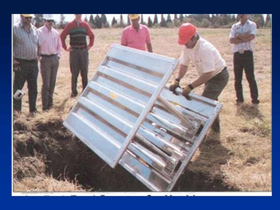
Nice system for shallow trenches 130 lbs overall weight

89
What's good? What’s not so good?
Good – easy system to use, a lot of work done quickly. Bad – not tall enough, no ladder What’s not so good?

90
Shield Used with Sloping
Unsupported utilities, no ladder, how much vibration does a freight train make?

91
Horizontal Shoring Dimensions
© ACR Publications Used By Permission

92
Vertical Shoring Dimensions
© ACR Publications Used By Permission

93
Pneumatic Systems Pneumatic system to mechanical

94
SHIELD USAGE AND SAFETY Shields are used to protect workers from cave-ins, not to provide support for the trench. Manufacturer’s Data must be present at work site. Top of the shield must extend to the top of the trench. If used with sloping, top of shield must extend 18 inches above vertical trench walls. Shields may be stacked, provided the bottom one is rated for the total depth of the trench. The trench may be dug 2 feet lower than the shield bottom, but the shield must be rated for that depth. Backfill around the box to prevent lateral movement. Trench boxes must be designed to be stacked.You can put any box on top of another

95
Review Table Top Exercise

96
Soil Classification 1926 Subpart P App A
Cemented soil Cohesive soil Dry soil Fissured Granular soil Layered system Moist soil Plastic Saturated soil Soil classification system Stable rock Submerged soil Unconfined compressive strength Wet soil

97
Soil Category: Stable Rock
Natural solid mineral material that can be excavated with vertical sides and remain intact while exposed. Examples are granite and sandstone. Determining whether a deposit is stable rock may be difficult unless it is known whether cracks exist and whether or not the cracks run into or away from the excavation.

98
Soil Classifications Stable rock Type A
cohesive soils with an unconfined compressive strength of 1.5 tons per square foot [tsf] Clay, silty clay, sandy clay NO SOIL IS A, IF FISSURED, SUBJECT TO VIBRATION, PREVIOUSED DISTURBED,SEEPING WATER SOIL TEST VISUAL- SIDES OF TRENCH FOR LAYERING EVIDENCE OF WATER PREVIOUSLY DIETURBED SOIL TENSION CRACKS, SPALLING, BOILING MANUAL TEST PLASTICITY DRY SRRENGTH THUMB PRENETRATION

99
Soil Classifications No soil is type A if; Fissured
Subject to vibration Previously disturbed Seeping water Part of a sloped or layered system of four horizontal to one vertical

100
Soil Fissuring How soon will it fail?

101
To Much Water? What do you have to do to make this trench safe?

102
Weight and Vibration How much pressure does it take from an outrigger to make this trench fail

103
Soil Classifications Type B
cohesive soils with an unconfined compressive strength greater than 0.5 tsf but less than 1.5 tsf Silt, silt loam, angular gravel soils that are fissured,or subject to vibration PREVIOUSLY DISTURBED UNLESS CLASSIFIED AS C. Define Silt and Loam type soils

104
Soil Classification Type - C
cohesive soils with a unconfined compressive strength of 0.5 tsf or less gravel, sand, loamy sand, submerged soil, soil from which water is freely seeping

105
SOIL STRENGTH MEASURE Unconfined Compressive Strength (UCS)
The amount of pressure in tons per square foot (tsf) required to cause the soil to fail in compression. OSHA Soil Classification is based on the UCS of the soil. Tests are usually done in the lab.
 required to cause the soil to fail in compression. OSHA Soil Classification is based on the UCS of the soil. Tests are usually done in the lab.")
106
Basis of classification
The classification of deposits shall be made based on the results of at least one visual and one manual analysis conducted by a competent person

107
Acceptable visual test
Determine qualitative information on site in general Soil adjacent to excavation Soil forming the sides of the open excavation Soil taken as samples from excavated material Estimate range of particle sizes

108
Acceptable visual test
Observe evidence of surface water Water seeping from the sides Location of the level of the water table Sources of vibration that may affect stability Evidence of previously disturbed soil

109
Acceptable manual test
Plasticity Ribbon and thread test Dry strength test Thumb penetration test Other strength test Pocket pentrometer Hand-operated shearvane

110
Field Sedimentation Test
Flat bottom container - at least inches high (old olive jar) 1 1/2 to 2 inches of soil Place soil in the glass jar 5 inches of water on top of soil
 1 1/2 to 2 inches of soil. Place soil in the glass jar. 5 inches of water on top of soil.")
111
After 30 seconds granular sand type material settles at the bottom
After 3 minutes silt type material settles on top of the sand

112
10% clay 10% silt 80% sand

113
The Ribbon Test Mix soil + water to make into plastic mass
Roll mass into cylindrical shape 1/2 to 3/4 inch diameter Lay across palm of hand Press between thumb and second joint of index finger

114
The Ribbon Test (continued)
Pass through thumb Squeeze until it takes the shape of a 1/8 to 1/4 inch thick strip Allow to hang freely from hand

115
The Ribbon Test (continued)
Clay loam will barely ribbon and break easily Clay = relatively long ribbon 6 to 8 inches or more More clay = longer and stronger ribbon Silt has tendency to produce short ribbon with broken appearance

116
Penciling If a 2 inch or longer thread can be held without breaking, the soil is cohesive.

117
Measures Soil’s Shear Strength
Shearvane/Torvane Measures Soil’s Shear Strength

118
Shearvane/Torvane Select fresh clod or block of undisturbed soil from spoil pile Cut a smooth surface on the clod Insert vanes of device into the soil Retract vanes to show foot imprint Set indicator at zero Hold device firmly against soil and twist in clockwise manner until soil fails in shear

119
Pocket Penetrometer Test
Device is designed to work on saturated clay soil Measures unconfined compressive strength of soil Twice the value of shear strength of same soil Note machine ring

120
Pocket Penetrometer

121
Pocket Penetrometer Test
To begin test, remove red protective cap, push ring against body so that low side reads “O” Slowly insert piston until engraved mark is level with soil

122
Pocket Penetrometer Test
Read strength in tons/sq ft using low side of ring (side closest to the piston end). Record reading and repeat step #1. For weak soils, use 1” adaptor foot, multiply by .0625
. Record reading and repeat step #1. For weak soils, use 1 adaptor foot, multiply by")
123
Thumb Penetration Test
The thumb penetration procedure involves an attempt to press the thumb firmly into the soil in question. OSHA TECHNICAL MANUAL – SECTIONV: CHAPTER2

124
Thumb Penetration Test
If the thumb makes an indentation in the soil only with great difficulty, the soil is probably Type A. If the thumb penetrates no further then the length of the thumb nail, it is probably Type B soil. OSHA TECHNICAL MANUAL – SETION V: CHAPTER 2

125
Thumb Penetration Test
If the thumb penetrates the full length of the thumb it is Type C soil. The thumb test is subjective and is therefore the least accurate of the tests. OSHA TECHNICAL MANUAL – SECTION V: CHAPTER 2

126
Soil Classifications Layered Geological Strata
where soils are configured in layers must be classified on the basis of the weakest soil each layer may be classified individually if a more stable layer lies below a less stable layer Type C soil rests on top of stable rock

127
Soil Classifications Look for the following conditions Particle size
Primarily fine grained=cohesive material Primarily coarse-grained sand or gravel Granular material Cohesion Remains in clumps=cohesive

128
Soil Strength is Dependent Upon:
Type of Soil. Amount of Moisture in the Soil. Whether the Soil Has Been Previously Disturbed.

129
If Water is Added It Brings Additional Weight
Hydrostatic Pressure It Erodes the Trench Wall Water movement typically moves soil It Can Freeze and Thaw Resulting in cracks & false cohesion REMOVAL OF GROUND WATER IS CRITICAL

130
SOIL COMPONENTS Clay: Silt: Sand: Gravel:
Composed of mineral particles less than mm in diameter Silt: Individual mineral fragments that range from to 0.05 mm in diameter. Sand: Individual rock or mineral fragments that range in diameter from 0.05 to 2.0 mm in diameter. Gravel: Can be either angular or rounded.

131
COHESIVE SOIL Soil with a high clay content which has cohesive strength. It does not crumble. It can be excavated with vertical side slopes. It is hard to break up when dry. It can be molded. It exhibits significant cohesion even when submerged.

132
GRANULAR SOIL Soils that include gravel, sand, silt.
Very low clay content. It has no cohesive strength. Some moist granular soils exhibit apparent cohesion. It cannot be molded when moist and crumbles easily when dry.

133
Soil Mechanics Toppling occurs when the trench’s vertical face shears along the tension crack line and topples into the excavation

134
Toppling into the trench

135
Soil Mechanics Subsidence and bulging occurs when an unsupported excavation can create an unbalanced stress in the soil which causes subsidence at the surface and bulging of the vertical face

136
Can the weight of this crane cause bulge or failure

137
Where is the crane. Is the gas line supported. What shoring?

138
Soil Mechanics Heaving or squeezing is caused by the downward pressure created by the weight of adjoining soil or equipment Can occur even when shoring or shielding has been properly installed

139
Forces Acting on a Trench
© ACR Publications Used By Permission

140
Soil Mechanics Boiling is evidenced by an upward water flow into the bottom of the cut High water table is one cause Boiling produces a quick condition even when trench boxes are used

141
Trench Boiling Boiling and toe failure

142
Soil Mechanics Tension cracks usually form at a horizontal distance of 0.5 to .75 times the depth of the trench

143
Soil Mechanics Sliding or sloughing may occur as a result of tension cracks

144
Sloping and Benching 1926 Subpart P App B
Actual slope Distress Maximum allowable slope Short term exposure Stable rock Type A soil Type B soil Type C soil

145
Design of Sloping and Benching
Allowable configurations and slopes Not steeper than 11/2 horizontal to 1 vertical Designs using other tabulated data Shall be in written form Must identify limits of use of the data Identify the registered professional engineer who approved

146
An attempt at sloping?

147
Benching?

148
Allowable Slopes Soil type Height/depth Slope angle
Stable rock Vertical 90 deg Type A ¾ to deg Type B 1 to deg Type C 11/2 to deg Type A short term ½ to deg max excavation depth 12 ft

149
Examples of Sloping for Different Soils
Type A Type B Type C

150
Only to be used on soil types A and B
BENCHING Only to be used on soil types A and B Type A Type B

151
Allowable Slopes Type A soil
Supported of shielded vertically sided lower portion ¾ to 1 20 feet max depth Shield 18 inches above to prevent rollover

152
Allowable Slopes Type B soil
Supported of shielded vertically sided lower portion 1 to 1 sloped 18 inches minimum at top of shield to prevent rollover

153
Allowable Slopes Type C soil supported of shielded vertically sided lower portion 1 ½ to 1 20 feet max depth 18 inches above to prevent rollover

154
Slope Configurations Excavations in Layered Soils

155
Slope Configurations Excavations in Layered Soil

156
Excavations in Type A Soils

157
Timber Shoring for Trenches 1926 Subpart P App C
Basis and limitations of data Trenches do not exceed 20 ft in depth Each table presents the minimum sizes of timber members to use in a shoring system Tables are taken from National Bureau of Standards

158
Timber system being built

159
Timber Shoring Timber system in place

160
Timber Shoring

161
Aluminum Hydraulic Shoring 1926 Subpart P App D
Basis and limitations of data Vertical shore rails and horizontal wales Meet equivalent strength properties 2 inch cylinder inside diameter minimum safe working capacity of no less than lbs compressive load at maximum extension 3 inch cylinder inside diameter safe working load not less than lbs axial compressive load Vertical shores used must be minimum of 3 spaced equally

162
Aluminum Hydraulic

163
Aluminum Hydraulic

164
Aluminum Hydraulic Aluminum hydraulic shoring

165
Aluminum Hydraulic Aluminum hydraulic shoring

166
Spot-bracing Usage Aluminum hydraulic shoring

167
Hydraulic Shoring Usage

168
Alternatives to Timber Shoring 1926 Subpart P App E

169
Alternatives to Timber Shoring 1926 Subpart P App E

170
Alternatives to Timber Shoring 1926 Subpart P App E

171
Pneumatic shoring with ventilation being used in rescue

172
Selection of Protective Systems 1926 Subpart P App F

173
Selection of Protective Systems 1926 Subpart P App F

175
Other Factors Influencing Cave-Ins
Intersecting Trenches Previously Disturbed Vibration Surcharged Load Inclined Layers Drying / Saturation Free standing time

176
Fallacies And Misconceptions
At what depth/width do most incidents occur Between 6-8 ft deep and less than 6 ft wide Most utilities found in this area

177
Fallacies And Misconceptions
Most incidents occur in bad weather False Good weather - crews are more careful in bad weather FREEZING GROUND THAWING DRYING OUT WARM TURNING COLD

178
Fallacies And Misconceptions
Clay is the least dangerous soil type False Clay looks strong but it is very deceptive - most fatal trench accidents occur in clay soil

179
THE TYPICAL CAVE-IN © ACR Publications Used By Permission

180
Summary Excavation laws, regulations, standards Soil classification
Soil testing Competent person responsibilities Hazards associated with trenches Protective systems

181
KEEP THE JOB SAFE SO YOU CAN GO HOME SAFE!

Similar presentations