Download presentation
Presentation is loading. Please wait.

1
WELDING INSPECTION AND QUALITY CONTROL
TASK # 2: FLAWS/DISCONTINUITIES / DEFECTS WHY IS IT IMPORTANT FOR YOU TO LEARN THIS SKILL? UPON COMPLETION OF THIS MODULE YOU WILL BE ABLE TO: DIFFERENTIATE FLAWS, DISCONTINUITIES AND DEFECTS. DEFINE THE MAJOR CLASSIFICATION OF WELD DEFECTS IDENTIFY DEFECTS, ITS CAUSES AND ITS REMEDIES ACCEPTANCE STANDARDS

2
Discontinuity All Welds have flaws. Another name for a flaw is a discontinuity Discontinuities are interruptions in the normal crystalline structure (or grain) of the metal. Discontinuities are NOT always defects Defect A flaw or flaws that by nature or accumulated effect render a part or product unable to meet minimum applicable acceptance standards or specifications. The term designates rejectability.
 of the metal. Discontinuities are NOT always defects. Defect. A flaw or flaws that by nature or accumulated effect render a part or product unable to meet minimum applicable acceptance standards or specifications. The term designates rejectability.")
3
Acceptance Standards CODE requirements Users standards
Sample of Codes and Standards AWS – American Welding Society API – American Petroleum Institute ASME – American Society of Mechanical Engineers ABS – American Bureau of Shipping

4
The purpose of welding inspections is to locate and determine the size of any discontinuities
Discontinuities that are too large or repeated too often within the weld become defects Defects will compromise the welds overall strength

5
What are some common defects?
CLASSIFICATION SYSTEM AND TYPES DRAWING AND DIMENSIONAL STRUCTURAL DISCONTINUITIES IN WELDS PROPERTIES(Mechanical and Chemical) of weld metal and or base metal. Dimensional 1. Warpage-Longitudinal Distortion-Angular
 of weld metal and or base metal. Dimensional. 1. Warpage-Longitudinal Distortion-Angular.")
6
b. Causes of warpage / distortion – 1
b. Causes of warpage / distortion – 1. shrinkage of weld metal and overheating of joint, 2. faulty preparation 3. faulty clamping or weak tacking c. Controlling methods 1. proper bead sequence 2. correct preparation 3. intermittent welding 4. correct clamping, proper tack size, prewarp d. Correction method – straightening operation, heating, removal of welds and subsequent re-welding e. Effects 1. builds stress 2. failure to meet design dimensions

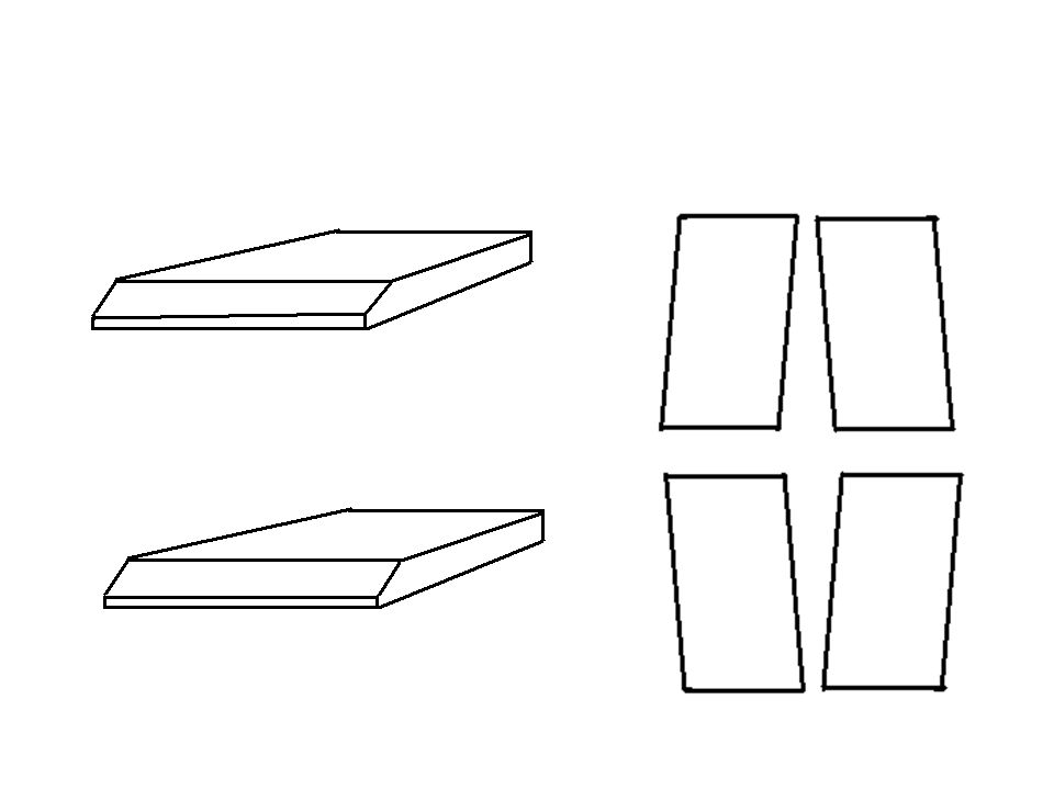
7
Joint Preparation Correct Bevel Angle Correct Root Gap
Correct Root Face Proper Tack Weld Proper Alignment

8
2. failure to issue proper instructions
2. Incorrect Joint Preparation a. Types 1. bevel angle 2. groove angle 3. root opening or root gap 4. root face b. Causes 1. improper methods used 2. failure to issue proper instructions 3. failure to follow instructions 4. use of improper symbols c. Controlling methods 1. use proper instructions 2. use of correct symbols 3. use correct techniques d. Corrections methods 1. prepare again using proper methods e. Effects–warpage/trapped slag/incomplete fusion/improper bead shape

12
Concavity Fillet weld Corner joint

13
Convexity Fillet weld Corner joint

14
Excessive Concavity or Convexity
Incorrect weld size Excessive Concavity or Convexity Types 1. excessive convexity/incorrect length 2. excessive concavity / excessive root reinforcement Causes 1. improper welding technique 2. failure to follow instruction 3. insufficient or excessive welding current Controlling Methods 1. use proper technique 2. follow instruction d. Correction Methods 1. removal of welds and subsequent welding Effects 1. notch effect 2. concentration of stress under load 3. insufficient throat thickness

15
EXCESSIVE CONVEXITY

16
EXCESSIVE CONCAVITY

17
EXCESSIVE WELD REINFORCEMENT
Incorrect weld profile EXCESSIVE WELD REINFORCEMENT Tie end

18
Excessive Face Reinforcement

19
Excessive Root Reinforcement
Insufficient penetration Burn through Narrow root gap

20
4. Incorrect Weld Profile
Type 1. excessive root reinforcement 2. excessive face reinforcement Causes 1. slow travel speed 2. excessive heat 3. incorrect root face 4. improper electrode angle c. Controlling methods 1. increase travel speed 2. reduce heat 3. use correct preparation 4. use correct electrode angle d. Correction methods 1. removal of excessive reinforcement 2. possible removal of welds and subsequent re-welding Effects – concentration of stress under load/notch effect

21
5. Incorrect Final Dimension
Types 1. Too long / Too short Causes 1. incorrect tolerance on drawings or specifications 2. shrinkage of welds 3. incorrect joint preparation c. Controlling methods 1. inspect for correct dimensions or tolerances prior to fabrication d. Correction methods 1. possible removal of welds and subsequent re-welding e. Effects 1. will change dimensions of entire product

22
Structural Discontinuities
Porosity Slag inclusion Tungsten Inclusion Poor penetration Undercut Cracks Lack of Fusion Burn Through Rollover or “Cold Lap”

23
Structural Discontinuities in Weld
POROSITY- Gas entrapment

24
Sample of Defective Welds
Porosity would likely to occur at starting the weld, Tie Ins. Over reinforcement

25
Sample of Defective Welds
A. Porosity Causes: 1.Welding speed too rapid 2.Current too low 3.High sulphur or other impurities 4.Faulty electrodes

26
Porosity Types 1. uniformly scattered porosity 2. cluster porosity 3. linear porosity b. Causes 1. dirt, grease, rust, oil, moisture on base metal 2. excessive current 3. moisture in shielding gas 4. moisture in filler metals c. Controlling methods 1. clean base metal properly 2. dry base metal and/or filler materials 3. proper welding technique d. Corrective methods 1. removal of defective area and subsequent re-welding e. Effect depending on nature and type can propagate into a crack

27
2. Slag Inclusions Type 1. slag at root of joint 2. slag at bond area 3. scattered slag inclusions b. Causes 1. improper joint preparation 2. improper cleaning of welds 3. improper techniques – wrong current setting - wrong travel or speed c. Controlling methods 1. proper joint preparation 2. proper cleaning before welding another bead 3. use proper technique – adjust current setting, - adjust travel or speed d. Corrective methods 1. removal of defective area and subsequent re-welding e. Effect – weld is weak and cause cracking

28
Sample of Defective Welds
B. Slag Inclusion Causes: 1.Joint design: sharp V-shaped recess 2.High viscosity of molten metal, rapid chilling, too low a weld temperature Slag are not complete remove before depositing another bead.

30
3. Tungsten Inclusions Type 1. Scattered inclusions b. Causes 1. touching the electrode to the work or molten weld metal 2. incorrect current type and or current setting 3. incorrect type and or size of tungsten electrode c. Controlling methods 1. use proper welding technique 2. use correct type and current setting 3. use correct type and size of tungsten electrode d. Correction method 1. removal of defective area and subsequent re-welding e. Effects 1. creates brittle area 2. can cause cracking Note: can be seen as white image in x-ray film.

31
4. Incomplete Fusion Type 1. incomplete fusion at the root of the weld or adjacent layers of weld metal b. Causes 1. inadequate amount of heat (low current setting) 2. incorrect electrode angle 3. travel speed too fast 4. incorrect joint preparation c. Controlling Methods 1. increase amount of heat (increase current setting) 2. reduce travel speed 3. use correct electrode angle 4. use proper joint preparation d. Correction methods 1. possible back gouge and re-weld 2. removal of defective area and subsequent re-welding e. Effect – weak joint and can cause cracking
 2. incorrect electrode angle. 3. travel speed too fast. 4. incorrect joint preparation. c. Controlling Methods. 1. increase amount of heat (increase current setting) 2. reduce travel speed. 3. use correct electrode angle. 4. use proper joint preparation. d. Correction methods. 1. possible back gouge and re-weld. 2. removal of defective area and subsequent re-welding. e. Effect – weak joint and can cause cracking.")
32
4. Incomplete fusion at the root of the weld
Corner edge of the joint is not melted

33
4. INCOMPLETE FUSION at adjacent of the weld

34
5. Incomplete joint penetration
Type 1. lack of complete fill at the root of the joint / either butt joint or tee joint. b. Causes 1. groove design not suited for the process 2. root face dimension is too great (thick) 3. root opening is too small 4. fast travel speed 5. insufficient welding current c. Controlling methods 1. use proper joint design 2. reduce travel speed 3. increase current setting d. Correction method 1. possible back gouge and re-weld 2. removal of defective area and subsequent re-welding e. Effects – notch effect possible start cracks
 3. root opening is too small. 4. fast travel speed. 5. insufficient welding current. c. Controlling methods. 1. use proper joint design. 2. reduce travel speed. 3. increase current setting. d. Correction method. 1. possible back gouge and re-weld. 2. removal of defective area and subsequent re-welding. e. Effects – notch effect possible start cracks.")
35
Inadequate joint penetration

36
Defective Root Penetration
Lack of penetration: Causes: 1.Too long arc 2.Wrong fit-up or root gap 3. Low current rating 4. Faulty electrode size 5. Wrong travel speed

37
Defective Root Penetration
keyhole Keyhole = root gap + 1/16” on both sides is the recommended size. Burn Through / Melt through

38
Defective Root Penetration
Lack of Penetration In tie ins

39
Insufficient Fill on the Root Side (suckback)
Definition: The weld surface is below the adjacent surfaces of the base metal at the weld root. Cause: Typically improper joint preparation or excessive weld pool heat. Prevention: Correct cause. Repair: Backweld to fill. May requireremoval of weld section by grinding for access to the joint root.

40
EXCESSIVE PENETRATION&INCOMPLETE PENETRATION

41
6. Undercut Types 1. side wall undercut 2. surface toe line undercut b. Causes 1. excessive current (too high current) 2. too long arc length 3. magnetic arc blow (DC welding) 4. excessive travel speed (travel too fast) 5. incorrect electrode angle c. Controlling methods 1. reduce current 2. adjust arc length 3. use AC welding 4. reduce travel speed 5. observe electrode angle
 4. excessive travel speed (travel too fast) 5. incorrect electrode angle. c. Controlling methods. 1. reduce current. 2. adjust arc length. 3. use AC welding. 4. reduce travel speed. 5. observe electrode angle.")
42
d. Correction methods 1. grinding or removal of defective area and subsequent re-welding. e. Effects 1. reduces strength of the joint 2. can cause slag inclusion

43
Undercut Definition: A groove cut at the toe of the weld and left unfilled. Cause: High amperage, electrode angle, long arc length, rust Prevention: Set machine on scrap metal. Clean metal before welding. Repair: Weld with smaller electrode, sometimes must be low hydrogen with preheat. Sometimes must gouge first.

44
UNDERCUT

45
Undercut D. Undercutting Causes: 1.Current too high
2.Arc length too long 3.Improper manipulation of the electrode 4. Welding speed too rapid

46
Undercut typically has an allowable limit
Undercut typically has an allowable limit. Different codes and standards vary greatly in the allowable amount. Plate - the lesser of 1/32” or 5% (typical)
")
47
7. Cracks Types 1. transverse and longitudinal weld cracks 2. crater cracks 3. base metal cracking b. Causes 1. localized stress exceeds the ultimate strength of the material 2. lack of pre heat 3. poor crater fill technique c. Controlling methods 1. use pre heating 2. use low hydrogen electrodes 3. sequence welds to balance shrinkage 4. use proper crater fill technique 5. avoid quenching and cooling conditions

48
d. Correction method 1. grinding / removal of defective area and subsequent re-welding e. Effects 1. weld failure 2. cracks progress in length (increase of crack length)
")
49
Cracks

50
CRATER CRACKS INSUFFICIENT FILLING AT THE END OF THE WELD

51
8. Surface irregularities
Types 1. depressions 2. varying surface welds 3. varying reinforcement 4. non uniform weld ripples 5. spatter b. Causes 1. inexperienced welder 2. restricted positioning while welding c. Controlling methods 1. proper training of welders 2. workmanship samples d. Correction methods 1. grinding or chipping before depositing succeeding welds e. Effects 1. could result in slag entrapment or other discontinuities

52
OVERLAP

53
Insufficient Fill Definition: The weld surface is below the adjacent surfaces of the base metal Cause: Improper welding techniques Prevention: Apply proper welding techniques for the weld type and position. Use stripper beads before the cover pass. Repair: Simply weld to fill. May require preparation by grinding.

54
UNDERFILL

55
Surface Irregularities
SPATTER

56
POOR APPEARANCE Crater Incomplete Termination of Weldment

57
UNACCEPTABLE WELD PROFILES

58
Properties (Mechanical and Chemical) of Welded Metal and/or Base Metal
Tensile strength – ultimate strength of a material subjected to a tensile load Yield strength – indication of maximum stress that can be developed in a material without with out plastic deformation. Ductility – extent to which a material can sustain palstic deformation without rupture Hardness – measure of a materials resistance to localized plastic deformation Impact – energy required to fracture a part subjected to shock loading Chemical Composition – the structure and properties of substances and of the changes they undergo.

59
How would you find these faults ?
TWO METHODS OF DETERMINING WELD FAULTS 1. Non Destructive Examination 2. DESTRUCTIVE TESTING

60
Standard Acceptability of welding defects:
1. Undercut should not exceed 1/32” inch(0.8mm) width and depth or must not exceed to 5% thickness from base metal. 2. No porosity shall exceed 1/16 inch (1.6mm) or in addition no square inch of weld metal shall exceed 1/16 inch(1.6mm) in greatest dimensions. 3. No gas pocket on square inch of weld metal area shall contain more than 6 gas pocket exceeding 1/16 inch (1.6mm) in greatest dimensions. 4. No slag inclusion shall exceed 1/8 inch (3.2mm) in every 6 inches of weld.
 width and depth or must not exceed to 5% thickness from base metal. 2. No porosity shall exceed 1/16 inch (1.6mm) or in addition no square inch of weld metal shall exceed 1/16 inch(1.6mm) in greatest dimensions. 3. No gas pocket on square inch of weld metal area shall contain more than 6 gas pocket exceeding 1/16 inch (1.6mm) in greatest dimensions. 4. No slag inclusion shall exceed 1/8 inch (3.2mm) in every 6 inches of weld.")
61
Florence-Darlington Technical College
Excerpts from: Tim Turner Elizabethtown Technical College Wanda S. Benton Florence-Darlington Technical College

Similar presentations


 and Weld Joint Design>")


, Resistance Seam Welding (RSEW),& Resistance Projection.>")
>")


