Download presentation
Presentation is loading. Please wait.

1
Virtual LAN

2
Using Hubs Layer 1 devices Inexpensive In one port, out the others
One collision domain One broadcast domain

3
This is fine for small workgroups, but does not scale well for larger workgroups or heavy traffic.

4
What if the computers were on two different subnets
What if the computers were on two different subnets? Could they communicate within their own subnet? Yes Between subnets? No, need a router.

5
Same issues as before, with more of an impact on the network.

6
Using Switches Layer 2 devices
Moderate expense for common access switches, but can be very expensive. Layer 2 filtering based on Destination MAC addresses and Source Address Table One collision domain per port One broadcast domain

7
Two parallel paths: (complete SAT tables)
Data traffic from to and from to

8
As opposed to the Hub: Data traffic from 172.30.1.21 to 172.30.1.22
and from to Collision!

9
Collisions and Switches:
What happens when two devices on a switch, send data to another device on the switch. to and to

10
The switch keeps the frames in buffer memory, and queues the traffic for the host This means that the sending hosts do not know about the collisions and do not have to re-send the frames. Frames in buffer

11
Other Switching Features
Review Asymmetric ports: 10 Mbps and 100 Mbps Full-duplex ports Cut-through versus Store-and-Forward switching

12
Ports between switches and server ports are good candidates for higher bandwidth ports (100 Mbps) and full-duplex ports.
 and full-duplex ports.")
13
Introducing Multiple Subnets/Networks without Routers
Switches are Layer 2 devices Router are Layer 3 devices Data between subnets/networks must pass through a router.

14
A Switched Network with two subnets:
What are the issues? Can data travel within the subnet? Yes Can data travel between subnets? No, need a router! What is the impact of a layer 2 broadcast, like an ARP Request? ARP Request

15
All devices see the ARP Request
All devices see the ARP Request. One broadcast domain means the switches flood all broadcast out all ports, except the incoming port. Switches have no idea of the layer 3 information contained in the ARP Request. This consumes bandwidth on the network and processing cycles on the hosts.

16
One Solution: Physically separate the subnets. But still no data can travel between the subnets. How can we get the data to travel between the two subnets?

17
Introducing Multiple Subnets/Networks with Routers
Switches are Layer 2 devices Router are Layer 3 devices Data between subnets/networks must pass through a router.

18
Routed Network: Two separate broadcast domains, because the router will not forward the layer 2 broadcasts such as ARP Requests.

19
Switches with multiple subnets
So far this should have been a review. Lets see what happens when we have two subnets on a single switch and we want to route between the two subnets.

20
Router-on-a-stick: When a single interface is used to route between subnets or networks, this is know as a router-on-a-stick. To assign multiple ip addresses to the same interface, secondary addresses or subinterfaces are used. interface e 0 ip address ip address secondary

21
Router-on-a-stick Advantages
Useful when there are limited Ethernet interfaces on the router. Disadvantage Because a single link is used to connect multiple subnets, one link is having to carry the traffic for multiple subnets. Be sure this is link can handle the traffic. You may wish to use a high-speed link (100 Mbps) and full-duplex.
 and full-duplex.")
22
Gotcha’s 1. Remember to have the proper default gateway set for each host. hosts - default gateway is hosts - default gateway is 2. The router must still route between subnets, so you must include: Router (config)# router rip Router (config-router)# network
# router rip. Router (config-router)# network")
23
Multiple interfaces: Two Ethernet router ports may be used instead of one. However this may be difficult if you do not have enough Ethernet ports on your router. E0 E1

24
One switch two subnets:
Good News: Data can travel between subnets and we have two separate broadcast domains. Bad News: Hosts are on different subnets but on a single layer 2 broadcast domain. ARP Request

25
An ARP Request from for will still be seen by all hosts on the switch. The switch is a layer 2 device and will flood broadcast traffic out all ports, except the incoming port.

26
Introducing VLANs VLANs create separate broadcast domains
Routers are needed to pass information between different VLANs VLANs are not necessary to have separate subnets on a switched network, but as we will see they give us more advantages when it comes to things like data link (layer 2) broadcasts.
 broadcasts.")
27
VLAN Definition A logical subgroup within a local area network that is created via software rather than manually moving cables in the wiring closet. It combines user stations and network devices into a single unit regardless of the physical LAN segment they are attached to and allows traffic to flow more efficiently within populations of mutual interest. VLANs are implemented in port switching hubs and LAN switches and generally offer proprietary solutions. VLANs reduce the time it takes to implement moves, adds and changes. VLANs function at layer 2. Since their purpose is to isolate traffic within the VLAN, in order to bridge from one VLAN to another, a router is required. The router works at the higher layer 3 network protocol, which requires that network layer segments are identified and coordinated with the VLANs. This is a complicated job, and VLANs tend to break down as networks expand and more routers are encountered.

28
Layer 2 broadcast control:
An ARP Request from for will only be seen by hosts on that VLAN. The switch will flood broadcast traffic out only those ports belonging to that particular VLAN, in this case VLAN 1. ARP Request Switch Port: VLAN ID

29
Port-centric VLAN Switches
Remember, as the Network Administrator, it is your job to assign switch ports to the proper VLAN. This assignment is only done at the switch and not at the host. Note: The following diagrams show the VLAN below the host, but it is actually assigned within the switch.

30
Catalyst 1900 - VLAN Membership Configuration
Port VLAN Membership Type Static Static Static Static Static Static Static Static Static Static Static Static AUI Static A Static B Static [M] Membership type [V] VLAN assignment [R] Reconfirm dynamic membership [X] Exit to previous menu Enter Selection:

31
Layer 2 broadcast control:
Without VLANs, the ARP Request would be seen by all hosts. Again, consuming unnecessary network bandwidth and host processing cycles. ARP Request

32
With VLANs: Data will only travel within the VLAN. Remember that switches are Layer 2 devices and they can only pass traffic within the VLAN. ARP Request Switch Port: VLAN ID

33
Switch Port: VLAN ID

34
With VLANs: A switch cannot route data between different VLANs. Example: Data from to X Switch Port: VLAN ID

35
Gotcha’s 1. Remember that VLAN IDs (numbers) are assigned to the switch port and not to the host. (Port-centric VLAN switches) 2. Be sure to have all of the hosts on the same subnet belong to the same VLAN, or you will have problems. Hosts on subnet / VLAN 1 Hosts on subnet / VLAN 2 etc.

36
Routing and VLANs In the previous example data could travel within the VLAN, but not between VLANs. Just like subnets, a router is needed to route information between different VLANs. The advantage is the switch propagates broadcast traffic only within the VLAN.

37
Data between VLANs is routed through the router. Data from 172. 30. 1
Data between VLANs is routed through the router. Data from to

38
Gotcha’s 1. Remember to have the proper default gateway set for each host. hosts - default gateway is hosts - default gateway is 2. The router must still route between subnets, so you must include: Router (config)# router rip Router (config-router)# network 3. The switch ports to the router must have the corresponding VLAN ID to that subnet. Switch port to must be on VLAN 1 Switch port to must be on VLAN 2
# router rip. Router (config-router)# network The switch ports to the router must have the corresponding VLAN ID to that subnet. Switch port to must be on VLAN 1. Switch port to must be on VLAN 2.")
39
Switch Port: VLAN ID (VLAN ID not set at router.)
")
40
So, what’s the difference?
One of the main differences between subnets with VLANs and subnets without VLANs on switched networks, is that VLANs offer layer 2 broadcast control.

41
Here is an ARP Request example without VLANs.

42
Here is an ARP Request example with VLANs
Here is an ARP Request example with VLANs. Notice that the broadcast is isolated only to the VLAN that it came from, in this case VLAN 1. ARP Request

43
Can I use the Router-on-a-stick method with multiple VLANs?
Can you remind me what Router-on-a-stick is?

44
What is Router-on-a-stick?
When a single interface is used to route between subnets or networks, this is know as a router-on-a-stick. To assign multiple ip addresses to the same interface, secondary addresses or subinterfaces are used. interface e 0 ip address ip address secondary

45
With Router-on-a-stick, ISL or 802. 1Q trunking is needed
With Router-on-a-stick, ISL or 802.1Q trunking is needed. We will talk about tagging and trunking in the next section.

46
. VLAN introduction VLANs provide segmentation based on broadcast domains. VLANs logically segment switched networks based on the functions, project teams, or applications of the organization regardless of the physical location or connections to the network. All workstations and servers used by a particular workgroup share the same VLAN, regardless of the physical connection or location.

47
. VLAN introduction VLANs are created to provide segmentation services traditionally provided by physical routers in LAN configurations. VLANs address scalability, security, and network management. Routers in VLAN topologies provide broadcast filtering, security, and traffic flow management. Switches may not bridge any traffic between VLANs, as this would violate the integrity of the VLAN broadcast domain. Traffic should only be routed between VLANs.

48
Broadcast domains with VLANs and routers
. Broadcast domains with VLANs and routers A VLAN is a broadcast domain created by one or more switches. The network design above creates three separate broadcast domains.

49
Broadcast domains with VLANs and routers
/8 2) With or without VLANs /16 1) Without VLANs /16 /16 1) No VLANs, or in other words, One VLAN. Single IP network. 2) With or without VLANs. However this can be and example of no VLANS. In both examples, each group (switch) is on a different IP network. 3) Using VLANs. Switch is configured with the ports on the appropriate VLAN. What are the broadcast domains in each? One link per VLAN or a single VLAN Trunk (later) /16 1) With VLANs /16 /16
 With or without VLANs /16. 1) Without VLANs / /16. 1) No VLANs, or in other words, One VLAN. Single IP network. 2) With or without VLANs. However this can be and example of no VLANS. In both examples, each group (switch) is on a different IP network. 3) Using VLANs. Switch is configured with the ports on the appropriate VLAN. What are the broadcast domains in each One link per VLAN or a single VLAN Trunk (later) /16. 1) With VLANs / /16.")
50
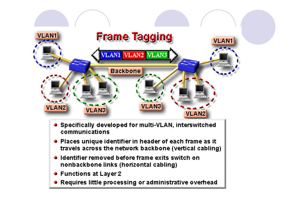
Tagging and Trunking

51
Non-tagging Switches Lets first see how multiple VLANs are interconnected using switches that do not have the tagging capability.

52
Non-tagging Switches For each VLAN, there must be a link between the two switches. One link per VLAN. Be sure the switch ports on the switches are configured for the proper VLAN. 100BaseT Ports Port 1 = VLAN 1 & Port 2 = VLAN 2 Moe VLAN 1: Port 1 on switch Moe is connected to Port 1 on Switch Larry. VLAN 2: Port 2 on switch Moe is connected to Port 2 on Switch Larry. Larry Port 1 = VLAN 1 & Port 2 = VLAN 2 100BaseT Ports

53
Advantages Each VLAN gets its own dedicated link with its own bandwidth. Disadvantages This requires a separate link for each VLAN. There may not be enough ports on the switch to accommodate a lot of different VLANs.

54
Introducing Tagging and Trunking

55
Some quick terminology
Channel - multiple links that carry a single VLAN (I.e. Fast-Etherchannel) Trunk - one link that carries multiple VLANs Tagging - used to Identify which VLAN a frame belongs to
 Trunk - one link that carries multiple VLANs. Tagging - used to Identify which VLAN a frame belongs to.")
56
Reminder: Switches and Routers
It is important to remember that hosts on different switches, can communicate with hosts which belong to their same subnet, without VLANs. It is also important to remember that if hosts on different subnets wish to communicate, then that traffic must be routed via a router.

57
VLANs and Switches However, if you put those hosts that are on different subnets, into different VLANs, then the switches will need to communicate the VLAN IDs. Again, this can be done without VLANs, but as we saw one of the benefits to VLANs is layer 2 broadcast control.

58
Trunking (or tagging) is needed between switches, or a switch and a router, to pass traffic for multiple VLANs, if a single link is used. Your switches must have ports that can do this trunking or tagging.

59
Advantages: A single port on a switch or router can be used to send and receive traffic for multiple VLANs. Disadvantages: This can put a lot of traffic on a single link, so be sure the link has enough bandwidth to handle it. This also requires the switch and/or router ports that are used for tagging to be capable of doing the tagging/trunking.

61
Tagging needed between the switches
Tagging needed between the switches. Note, that there is no router here, so there is no communications between the VLANs. Here is an example of sending information to

62
VLAN Network - Inter-switch VLANs
Two separate Broadcast Domains (VLAN 1 and VLAN 2) Communications over the trunk links (i.e. between switches) uses Tagging 802.1q ISL (Inter-Switch Link) - Cisco FDDI ATM LANE Tagging needed between the switches No communications between the VLANs, because there is not a router NOTE: VLAN ID is on the switches not on the hosts.
 Communications over the trunk links (i.e. between switches) uses Tagging q. ISL (Inter-Switch Link) - Cisco FDDI. ATM LANE. Tagging needed between the switches. No communications between the VLANs, because there is not a router. NOTE: VLAN ID is on the switches not on the hosts.")
63
Catalyst 1900 - VLAN Membership Configuration
Port VLAN Membership Type Static Static Static Static Static Static Static Static Static Static Static Static AUI Static A Static B Static [M] Membership type [V] VLAN assignment [R] Reconfirm dynamic membership [X] Exit to previous menu Enter Selection: NOTE: This is just an example of a switch configuration menu and does not show represent the configuration of the previous example.

64
The router is now connected, so we can see how to communicate between the VLANs. Because we are using Router-on-a-stick, the router will also need to be configured to include the ISL or 802.1Q tagging.

65
Same Gotcha’s 1. Remember to have the proper default gateway set for each host. hosts - default gateway is hosts - default gateway is 2. The router must still route between subnets, so you must include: Router (config)# router rip Router (config-router)# network 3. The switch ports to the router must have the corresponding VLAN ID to that subnet. Switch port to must be on VLAN 1 Switch port to must be on VLAN 2
# router rip. Router (config-router)# network The switch ports to the router must have the corresponding VLAN ID to that subnet. Switch port to must be on VLAN 1. Switch port to must be on VLAN 2.")
66
New Gotcha’s 4. Ports interconnecting switches must be capable of doing VLAN trunking, with either ISL or 802.1Q. 5. If you are using Router-on-a-stick, then the switch port and the router interface must be capable and configured to do trunking/tagging with either ISL or 802.1Q. 6. Remember, all traffic between different VLANs must be routed via the router. Question What if the router is not capable of doing the tagging or trunking? How can we use the router to switch between VLANs?

67
That’s right. You use two interfaces on the router instead of one
That’s right! You use two interfaces on the router instead of one. One for each VLAN. On the switch you will not need to use trunk ports for the router. No ISL or 802.1Q tagging is needed.

68
Would you like to see how the router is configured, with and without trunking?

69
Well, we will do it anyways. :-)
Instead of using secondary addresses, we will use something more current, know as subinterfaces. This allows you to configure multiple interfaces on a single physical interface. Cisco has said that secondary addresses will eventually not be a part of future IOS releases.

70
Router-on-a-stick, the router will also need to be configured to include the ISL or 802.1Q tagging. Secondary or subinterfaces can be used.

71
Using multiple Ethernet interfaces
Using multiple Ethernet interfaces. On the switch you will not need to use trunk ports for the router. No ISL or 802.1Q tagging is needed. Each switch port is on a separate VLAN.

72
Fast Etherchannel

73
Fast Etherchannel Allows two or four contiguous 100 Mbps ports to operate as a single link, giving twice the throughput. (command: port-channel mode on) 100BaseT Ports 10BaseT Ports (12) Moe A B Two 100BaseT Full-duplex ports: 2 x (100 x 2) = 400 Mbps throughput A B 10BaseT Ports (12) Larry 100BaseT Ports
 100BaseT Ports. 10BaseT Ports (12) Moe. A B. Two 100BaseT Full-duplex ports: 2 x (100 x 2) = 400 Mbps throughput. A B. 10BaseT Ports (12) Larry. 100BaseT Ports.")
74
Fast Etherchannel is a Cisco proprietary feature, although other vendors have a similar solution.
Fast Etherchannel allows some Cisco switches to use either two or four 100 Mbps ports as a single, virtual port. To the switch the multiple links will look like one, single, higher-bandwidth connection, combining the bandwidth of the two or four links between the two switches.

75
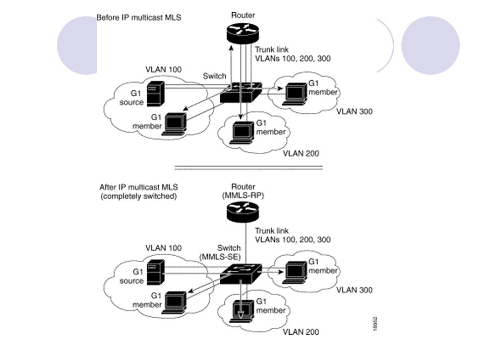
NetFlow Switching NetFlow Switching provides network layer switching to campus switches at high forwarding rates. The first packet of the “flow” is routed via the router. When a flow is detected, NetFlow switching establishes a cut-through path for all remaining packets in the flow. These can be switched by the switch and not routed by the router.

77
VLAN operation . Each switch port can be assigned to a different VLAN.
Ports assigned to the same VLAN share broadcasts. Ports that do not belong to that VLAN do not share these broadcasts.

78
. VLAN operation Static membership VLANs are called port-based and port-centric membership VLANs. As a device enters the network, it automatically assumes the VLAN membership of the port to which it is attached. “The default VLAN for every port in the switch is the management VLAN. The management VLAN is always VLAN 1 and may not be deleted.” This statement does not give the whole story. We will examine Management, Default and other VLANs at the end. All other ports on the switch may be reassigned to alternate VLANs. More on VLAN 1 later.

79
VLAN operation . Important notes on VLANs:
VLANs are assigned on the switch port. There is no “VLAN” assignment done on the host (usually). In order for a host to be a part of that VLAN, it must be assigned an IP address that belongs to the proper subnet. Remember: VLAN = Subnet
. In order for a host to be a part of that VLAN, it must be assigned an IP address that belongs to the proper subnet. Remember: VLAN = Subnet.")
80
. VLAN operation Dynamic membership VLANs are created through network management software. (Not as common as static VLANs) CiscoWorks 2000 or CiscoWorks for Switched Internetworks is used to create Dynamic VLANs. Dynamic VLANs allow for membership based on the MAC address of the device connected to the switch port. As a device enters the network, it queries a database within the switch for a VLAN membership.

81
Benefits of VLANs If a hub is connected to VLAN port on a switch, all devices on that hub must belong to the same VLAN. The key benefit of VLANs is that they permit the network administrator to organize the LAN logically instead of physically. Note: Can be done without VLANs, but VLANs limit the broadcast domains This means that an administrator is able to do all of the following: Easily move workstations on the LAN. Easily add workstations to the LAN. Easily change the LAN configuration. Easily control network traffic. Improve security.

82
Without VLANs – No Broadcast Control
ARP Request Without VLANs, the ARP Request would be seen by all hosts. Again, consuming unnecessary network bandwidth and host processing cycles.

83
With VLANs – Broadcast Control
Switch Port: VLAN ID ARP Request

84
VLAN Types

85
MAC address Based VLANs
. MAC address Based VLANs Rarely implemented.

86
Two Types of VLANs End-to-End or Campus-wide VLANs
. Two Types of VLANs End-to-End or Campus-wide VLANs Geographic or Local VLANs

87
End-to-End or Campus-wide VLANs
. End-to-End or Campus-wide VLANs

88
Geographic or Local VLANs
. Geographic or Local VLANs

89
End-to-End or Campus-wide VLANs
. End-to-End or Campus-wide VLANs End-to-End or Campus-wide VLANs Same VLAN/Subnet no matter what the location is on the network Trunking at the Core Usually not recommended by Cisco or other Vendors Adds complexity to network administration Does not resolve Layer 2 Spanning Tree issues Use to be recommended with routing at the Core was considered to slow.

90
End-to-End or Campus-wide VLANs
. End-to-End or Campus-wide VLANs The core layer router is being used to route between subnets (VLANs). The network is engineered, based on traffic flow patterns, to have 80 percent of the traffic contained within a VLAN. The remaining 20 percent crosses the router to the enterprise servers and to the Internet and WAN. Note: This is known as the 80/20 rule. With today’s traffic patterns, this rule is becoming obsolete.
. The network is engineered, based on traffic flow patterns, to have 80 percent of the traffic contained within a VLAN. The remaining 20 percent crosses the router to the enterprise servers and to the Internet and WAN. Note: This is known as the 80/20 rule. With today’s traffic patterns, this rule is becoming obsolete.")
91
Geographic or Local VLANs
. Geographic or Local VLANs Geographic or Local VLANs More common Routing at the core Different VLAN/Subnet depending upon location

92
Geographic or Local VLANs
As many corporate networks have moved to centralize their resources, end-to-end VLANs have become more difficult to maintain. Users are required to use many different resources, many of which are no longer in their VLAN. Because of this shift in placement and usage of resources, VLANs are now more frequently being created around geographic boundaries rather than commonality boundaries.

93
Geographic or Local VLANs
. Geographic or Local VLANs This geographic location can be as large as an entire building or as small as a single switch inside a wiring closet. In a VLAN structure, it is typical to find the new 20/80 rule in effect. 80 percent of the traffic is remote to the user and 20 percent of the traffic is local to the user. Although this topology means that the user must cross a Layer 3 device in order to reach 80 percent of the resources, this design allows the network to provide for a deterministic, consistent method of accessing resources.

Similar presentations

.>")


>")


>")
. Switches, also known as switching hubs, have become an increasingly important part of our networking today, because when working with hubs,>")
