Download presentation
Presentation is loading. Please wait.

1
Stormwater Design Adaptations for Karst Terrain in the Chesapeake Bay Watershed
Photo: Virginia DCR

2
Stormwater Training Partnership
The Chesapeake Bay Stormwater Training Partnership Visit: To learn how you can have access to: Discounted Webcasts Free One-day design workshops Intensive master stormwater design seminars Direct On-site technical assistance Self guided web-based learning modules

3
Welcome to the Webcast To Ask a Question – The lower left-hand corner of the screen contains a chat box. Click on the “Public” tab and type your question in the box and click on the arrow to submit it. We will try to answer as many questions as possible during the webcast. To Answer a Poll Question – Polling questions will appear throughout the webcast. To answer a poll question, click on the radio button to the left of your answer and click submit. Do not type your answer in the chat box. To Adjust How the Slides Appear on Your Screen – On the top of your screen, click on the small down arrow next to the button that looks like Scroll down to “Zoom” and click on “Auto Fit.”

4
Welcome to the Webcast To Complete the Webcast Survey – After the webcast, we will have a short multiple choice survey to get feedback on your experience. Please take a few minutes to fill the survey out so we can identify areas for improvement. Resources – After the webcast, we will a resources sheet, speaker contact information, and a pdf of the presentation.

5
Webcast Archive We will archive the webcast in a few weeks where it can be accessed at the Chesapeake Bay Stormwater Training Partnership website at

6
Chesapeake Stormwater Network 117 Ingleside Avenue Baltimore, MD 21228
Speaker Info Jim Lawrence Opequon Targeted Watershed Project 408 Marion Street Winchester, VA 22601 Tom Schueler Chesapeake Stormwater Network 117 Ingleside Avenue Baltimore, MD 21228

7
Webcast Agenda Karst: The Dissolving Landscape.
Challenges in Managing Stormwater in Karst Terrain The Site Assessment Process in Karst Stormwater Design in Karst Terrain Stormwater and the Safe Drinking Water Act Wrap-up

8
1. Karst: The Dissolving Landscape

9
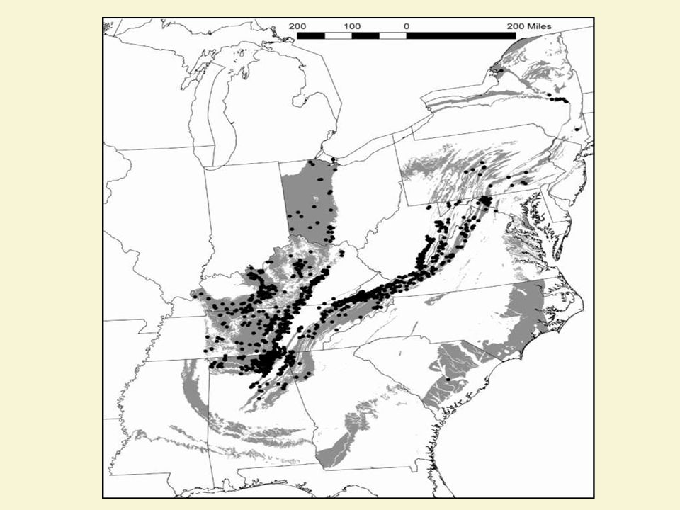
What Is Karst? Karst is a dynamic landscape characterized by sinkholes, springs, caves and a pinnacled, highly irregular soil rock interface that is the consequence of the presence of underlying carbonate geology such as limestone, dolomite or marble.

11
Surface and Subsurface Hydrology in Karst
Soils in karst terrain are moderately to poorly permeable, yet there is little surface runoff. Rainwater is diverted underground through sinkhole insurgences and/or by diffuse recharge into numerous small fractures in the limestone. Contaminants can pass rapidly from surface to subsurface waters with little or no modification Short residence times, confined aquifers, and lack of natural filtration creates special need for groundwater protection

14
very ancient and, in many areas, is deeply buried by residual soils
The Karst terrain of the Bay Watershed behaves differently than other regions very ancient and, in many areas, is deeply buried by residual soils

16
Unique Development Conditions where Karst is Found
Most is in the Ridge and Valley Province Extremely large lot ex-urban development Individual development projects are small Limited public water and sewer service Runoff reduction practices are new Limited experience by contractors, designers and reviewers

17
Why Karst is Different Post development runoff rates greatly increase
Karst is interspersed with non-karst at sites Highly variable subsurface conditions Surface/sub-surface drainage patterns poorly understood Confusing surface drainage patterns (losing streams) Lower stream density and more karst swales
 Lower stream density and more karst swales.")
18
Why Karst is Different Impervious cover dramatically increases site runoff Increased ponding or infiltration of the runoff can create new sinkholes Pollutants in runoff increase risk of groundwater contamination Rural development relies on wells for drinking water Increased sinkhole formation can damage local infrastructure (roads, buildings and BMPSe Sensitive endangered species found underground

19
CSN TECHNICAL BULLETIN No. 1
STORMWATER DESIGN GUIDELINES FOR KARST TERRAIN IN THE CHESAPEAKE BAY WATERSHED VERSION 2.0 JUNE, 2009 Workshops or charrettes such as the one pictured in the slide above are important tools that should be used early in the planning process of retrofits to inform and educate stakeholders.

20
Purpose of Technical Bulletin
Limited, conflicting and disjointed guidance available to local planners and engineers Consensus among diverse karst working group over last year Document can be incorporated by reference into state and local ordinances and development review policies Doesn’t eliminate all risk, but reduces it sharply compared to status quo

21
Special Thanks for the Karst Working Group
Chris Anderson, Page County, VA Twila Carr, West Virginia DEP Bob Denton, Potomac Environmental Services Tom Devilbiss, Carroll County, MD Mike Eller, EPA Region 3 Jim Lawrence, Virginia Tech Wil Orndorff, Virginia DCR Alana Hartman, WV DEP Michael Schwartz, Freshwater Institute Wayne Webb, Winchester VA Sherry Wilkins, WV DEP

22
Questions and Answers

23
2. Site Assessment for Karst Vulnerability

25
Preliminary Site Investigation
Assess whether site is vulnerable to karst problems Analysis of geologic and topographic maps, aerial photos and field visit by experienced professional Screen for proximity to known caves and sinkholes Product is site map showing location of suspected karst features & decision While caves/sinkholes are diagnostic, their absence does not mean karst is not a problem

26
Detailed Site Investigation
Used to develop a karst feature plan that identifies the location and elevation of subsurface voids, cavities and fractures Scope reflects the size and complexity of the development project Used to determine the nature and thickness of subsurface materials

27
Techniques for Assessing Subsurface Conditions
Electric resistivity tomography Seismic refraction Gravity surveys Electromagnetic (EM) inductance/conductivity surveys These surveys identify suspect areas to be further evaluated by borings
 inductance/conductivity surveys. These surveys identify suspect areas to be further evaluated by borings.")
28
Key Data to Collect at Site
Bedrock characteristics (type, contacts, faults, and structure)* Overlying soil characteristics (type, thickness, infil rate, water table, geologic parent)* Verification of geological contacts between karst and non-karst formations Photo-geologic fracture trace map * these are often spatially variable
* Overlying soil characteristics (type, thickness, infil rate, water table, geologic parent)* Verification of geological contacts between karst and non-karst formations. Photo-geologic fracture trace map. * these are often spatially variable.")
29
Key Data to Collect at Site
Locations of bedrock outcrops, sinkholes, cave openings, closed depressions, springs and other karst features Perennial, intermittent or ephemeral streams (flow behavior and surface/subsurface discharge points) Site scale “watershed” boundaries (1 ft or less contours) Public or private wells within ¼ mile of site
 Site scale watershed boundaries (1 ft or less contours) Public or private wells within ¼ mile of site.")
30
Adjust Site Plan Layout
Avoid karst when possible in site layout and when locating building pads and roads Minimize site disturbance and major cut/fill Minimize drainage alteration and protect existing flow paths (karst swales) Minimize site IC to reduce runoff Any existing sinkholes should be recorded and protected with buffers or easements Sensible location of wells and septic systems
 Minimize site IC to reduce runoff. Any existing sinkholes should be recorded and protected with buffers or easements. Sensible location of wells and septic systems.")
31
Karst Swale Protection (KSP) Areas
Centered on drainage-way or swale with width of 50 to 300 feet. Credit: Subtract twice the KSP area from the contributing IC area when computing WQv. No disturbance during construction Protected by conservation easement after construction Adjacent filter strips and internal spreaders can further enhance its performance

32
Assess Future Hotspot Status
A hotspot is future operation or activity on part or all of the site that generates highly polluted runoff and/or has a greater risk of spills leaks and discharges Localities can designate which types of development with potential to become hotspots If a site is designated as a hotspot, it influences how much runoff must be treated and whether it can be infiltrated or discharged to a sinkhole

33
Risk-Based Management Strategies for Hotspots
Depending on Hotspot Severity: Enhanced On-site Pollution Prevention Plans Treat at least 50% of WQv prior to Infiltration Prohibit Infiltration and Use Sand Filters Instead These rules also apply to other practices where infiltration may be expected after little or no treatment (e.g., dry ED ponds, grass swales, filter strips)
")
34
Industrial and Municipal Stormwater Hotspots
SWPP Required? Restricted Infiltration No Infiltration Facilities w/NPDES Industrial permits Yes ■ Public works yard ● Ports, shipyards and repair facilities Railroads/ equipment storage Auto and metal recyclers/scrap yards Petroleum storage facilities Highway maintenance facilities Wastewater, solid waste facilities Industrial machinery and equipment Trucks and trailers Airfields and aircraft maintenance areas Fleet storage areas

35
Commercial Stormwater Hotspot OperationS
SWPP Required? Restricted Infiltration No Infiltration Parking lots (40 or more parking spaces) ● Gas stations Highways (2500 ADT) Retail/wholesale vehicle/ equipment dealers Convenience stores/fast food restaurants Vehicle maintenance facilities Nurseries and garden centers Golf courses
 ● Gas stations. Highways (2500 ADT) Retail/wholesale vehicle/ equipment dealers. Convenience stores/fast food restaurants. Vehicle maintenance facilities. Nurseries and garden centers. Golf courses.")
36
Questions and Answers

37
Part 3 De-centralized Stormwater Design

38
Guiding Philosophy for Stormwater Design in Karst
Treat runoff in a series of small runoff reduction practices across the site Disperse flows to avoid ponding, flow concentration or extended soil saturation LID practices work well in karst with CDA less than a half acre Avoid big contributing areas and deep trenches/pools Define stormwater hotspots and ensure full treatment before discharge Increase setbacks from buildings and other infrastructure

39
Take Soil Borings At key locations near buildings, roads, conveyance and at centralized stormwater facilities Number and depth of borings depends on the karst feature plans and local requirements More guidance is contained in the Technical Bulletin

40
Modeling large storm events in karst
Adjustments are need to Curve Numbers when using TR-55 or TR-20 models These apply to predevelopment runoff computations Post-development runoff rates should be computed based on site impervious cover Do a second adjustment to curve numbers to reflect the effect of runoff reduction practices These prevent super-sized detention ponds

41
Curve Number Adjustments for Karst
Multipliers for Adjusting Predevelopment Runoff Quantities for Karst Impact Adapted from Laughland (2007) and VA DCR (1999) % of Drainage Area in Karst Design Storm Return Frequency 2-year Storm 10-year Storm 100-year Storm 100 0.33 0.43 0.50 80 0.38 0.51 0.62 60 0.55 0.66 0.74 40 0.73 0.80 0.85 20 0.91 0.92 0.93 1.00
 and VA DCR (1999) % of Drainage Area in Karst. Design Storm Return Frequency. 2-year Storm. 10-year Storm. 100-year Storm")
42
Step 6 Select Most Appropriate BMPs
Stormwater Practices in State Manuals are Classified as being: Preferred Adequate Discouraged Prohibited All require some design adaptation for karst

43
BMP Selection in Karst Preferred Accepted Discouraged Prohibited
Closed Bioretention Filter Strips Wet ponds Wet Swale Rain Tanks/Cisterns Small-scale Infiltration Dry ED ponds Large Scale Infiltration Green Roofs Grass Channel Open Bioretention Sand Filters Soil Compost Amendments Shallow Dry Swale Permeable Pavers Constructed Wetlands Roof Disconnection 43

44
Special Pond Design Criteria
Use of larger ponds highly discouraged in karst, especially wet ponds Temporary detention water elevations should not exceed six feet Liners required, with thickness and material based on proximity to bedrock/groundwater sensitivity Maintenance protocol to inspect and remediate sinkholes

47
Required Groundwater Protection Liners for Ponds in Karst Terrain
(WVDEP, 2006 and VA DCR, 1999) Pond Excavated at least Three Feet Above Bedrock 24 inches of soil with maximum hydraulic conductivity of 1 x 10⁻⁵ cm/sec Pond Excavated within Three Feet of Bedrock 24 inches of clay1 with maximum hydraulic conductivity of 1 x 10⁻⁶ cm/sec Pond Excavated Near Bedrock within wellhead protection area, in recharge area for domestic well or spring, or in area with high fracture density or significant geophysical anomalies. Synthetic liner with a minimum thickness of 60 ml. 1 Clay properties defined in the Technical Bulletin
 Pond Excavated at least Three Feet Above Bedrock. 24 inches of soil with maximum hydraulic conductivity of 1 x 10⁻⁵ cm/sec. Pond Excavated within Three Feet of Bedrock. 24 inches of clay1 with maximum hydraulic conductivity of 1 x 10⁻⁶ cm/sec. Pond Excavated Near Bedrock within wellhead protection area, in recharge area for domestic well or spring, or in area with high fracture density or significant geophysical anomalies. Synthetic liner with a minimum thickness of 60 ml. 1 Clay properties defined in the Technical Bulletin.")
48
Bioretention Design in Karst
Wide and shallow Use underdrain to daylight if bedrock is w/in 3 feet of bottom Add sump stone layer below underdrain to increase RR Keep contributing drainage areas small (1/2 acre or less) Increase up an down gradient setbacks to buildings and infrastructure Shallow media depths OK (2 to 3 feet) PREFERRED
 Increase up an down gradient setbacks to buildings and infrastructure. Shallow media depths OK (2 to 3 feet) PREFERRED.")
49
Rain Tank Design in Karst
Well suited to provide alternate water source in rural communities Above ground tanks are preferred to below ground Tanks can be combined with automated irrigation, rain gardens or other practices to increase overflow treatment Tank overflows should extend 15 feet from foundation PREFERRED

50
Rooftop Disconnection Design for Karst
Need to provide a 15 foot setback from foundation Some kind of flexible pipe, buried just underground Connect the pipe to a small depression, rain garden or mini-dry well to spread out runoff Discharge to a turf filter corridor, filter strip or karst swale Minimum 40 feet if it reconnects to IC or storm drain system PREFERRED

51
Filter Strip Design for Karst
Good idea to treat adjacent runoff to the boundaries of a karst swale protection area (KSP) Use shallow gravel diaphragms or short grass berms to help spread runoff Keep disturbance in filter strip area to a minimum and maintain native meadow or forest Drainage to each individual strip should be kept to a ½ acre or less PREFERRED
 Use shallow gravel diaphragms or short grass berms to help spread runoff. Keep disturbance in filter strip area to a minimum and maintain native meadow or forest. Drainage to each individual strip should be kept to a ½ acre or less. PREFERRED.")
52
Dry Swale Design for Karst
Try to locate them on predevelopment flow path Bottom invert should be at least two ft above bedrock Filter bed media can be less than 18 inches Lateral set back from roads Can often dispense with underdrain Tie it into an adequate channel or discharge to karst swale protection area PREFERRED

53
Sand Filter Design for Karst
Recommended practice to treat runoff from hotspots Bottom invert should be two feet above bedrock Minimum depth of sand bed can be reduced to 18 to 24 inches Filter bottom should be closed and be water tight PREFERRED

54
Grass Channel Design for Karst
Incorporate soil compost amendments along bottom to improve treatment Check dams are discouraged since they pond too much water. Spreaders that are flush with ground surface can spread flows evenly The minimum depth to the bedrock layer can be 18 inches. The grass channel may have off-line cells and should be tied into an adequate discharge point. ADEQUATE

55
Small-scale Infiltration Design
Max CDA of 20,000 square feet Maximize the surface area of the infiltration practice so that it is wider than it is deep Soil borings must show at least three feet of vertical separation exist between their bottom invert and the bedrock layer. In many cases, bioretention is preferred to infiltration in karst areas. 15 ft down-gradient and 25 feet up-gradient setback Prohibited if the contributing drainage areas is classified as a severe stormwater hotspot. ADEQUATE

56
Permeable Paver Design for Karst
Best to use micro and small scale applications Larger applications should have an impermeable bottom liner and under drains Use carbonate source of rocks for stone reservoir to preserve buffering capacity ADEQUATE

57
Constructed Wetland Design for Karst
Will generally need liner to hold water Shallow, linear, and multiple cell configurations are preferred Regenerative conveyance systems are worth testing (with sand and organic lenses) Use them leading to or in close proximity to KSPs ADEQUATE?
 Use them leading to or in close proximity to KSPs. ADEQUATE")
58
DISCOURAGED PRACTICES
Wet Ponds Dry ED Ponds High cost for testing and liners, and future sinkhole liability PROHIBITED PRACTICES Wet Swales (don’t work) Large Scale Infiltration Basins (CDA more than 20,000 SF of IC)
 Large Scale Infiltration Basins (CDA more than 20,000 SF of IC)")
59
Questions and Answers

60
Part 4. Karst and Drinking Water

61
The Safe Drinking Water Act
This federal act regulates the infiltration of stormwater in certain situations under the underground injection control (UIC) program State or federal permits are required in order to protect underground sources of drinking water from contamination Two kinds of stormwater discharge can be subject to UIC regulations in karst terrain Certain kinds of underground stormwater disposal (BMPs) Discharges to an existing “improved” sinkhole
 program. State or federal permits are required in order to protect underground sources of drinking water from contamination. Two kinds of stormwater discharge can be subject to UIC regulations in karst terrain. Certain kinds of underground stormwater disposal (BMPs) Discharges to an existing improved sinkhole.")
62
Underground Injection Permits
Class V permits are needed for shallow wells Any bored, drilled, driven shaft or dug hole that is deeper than its widest dimensions, or an improved sinkhole, or a subsurface fluid distribution system. Must notify appropriate state or federal permit authority

63
Each State Has its Own UIC Authority
Underground Injection Control Permit Agency in Each Bay State BAY STATE REGULATORY AUTHORITY MARYLAND MDE NEW YORK EPA REGION 2 * PENNSYLVANIA EPA REGION 3 * VIRGINIA WEST VIRGINIA WV DEP * in states where EPA administers the UIC program, Class 5 wells are “rule- authorized”, meaning that they do not require a permit, but the operator must contact the agency to inventory their well.

64
What is an improved sinkhole?
“ a naturally occurring karst depression or other natural crevice that has been modified by a man-made structure to direct fluids into the subsurface “ Man-made structures are pipes, swales, ditches or other devices that channel water toward and/or into an existing sinkhole Both the increased runoff from a development and the storm drain system qualify as discharge to an improved sinkhole

65
Stormwater Discharges to Improved Sinkholes
Sinkhole should be registered as Class V injection well Analyze for any public/private drinking wells w/in 1500 feet of sinkhole Dye tracing advised if wells are present Prevent increased runoff volumes from discharging to sinkhole, but maintain predevelopment stormwater volume Treat full water quality volume prior to sinkhole discharge using runoff reduction practices (one inch) Maintenance of stormwater practices a condition of underground injection permit
 Maintenance of stormwater practices a condition of underground injection permit.")
66
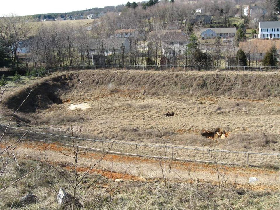
What if a Sinkhole is Created in a Stormwater BMP?
Maintenance Inspection Notification to Local Authority Sinkhole Investigation * Sinkhole Stabilization * Final Grading * The complexity of the methods depend on the depth and areal extent of the new sinkhole

67
Sinkhole Remediation: Lots Like a Bioretention Cross-Section

69
The Keys to Karst Understand the landscape below ground Detailed site planning and assessment Decentralized stormwater design Remove pollutants prior to underground discharge

70
Wrap-up

71
Webcast Resources More info, glossary and useful weblinks are provided in Technical Bulletin No. 1 which will be ed to you Also check out the CSN website at

72
Upcoming Webcasts – for 2010
June 13 Stormwater Design for Redevelopment Projects in MD (Register thru MAWP) September 1 Permeable Pavement Design, Installation, and Maintenance * October 20 Rooftop Disconnection, Filter Strips & Rainwater Harvesting * * Register at
 September 1 Permeable Pavement Design, Installation, and Maintenance * October 20 Rooftop Disconnection, Filter Strips & Rainwater Harvesting * * Register at")
73
Thanks Please take a minute to answer a multiple choice evaluation survey to improve future webcasts Or your comments directly to

Similar presentations