Download presentation
Presentation is loading. Please wait.

1
UDC Inspector Seminar 2007 Understanding Manufactured Home Installation Standards

2
Presenter – Ross Kinzler
Executive Director of Wisconsin Housing Alliance Presenter – Mike Zenner Inspection Services

3
Ross Kinzler With MH industry since 1989
Chief lobbyist for the industry

4
Mike Zenner Over 35 years of manufactured housing experience
Wick Quality Control Currently – Inspection Services AC inspections under the HUD Code UDC Construction and other creditials

5
What we’re going to learn
Basics of the HUD Code Installation standard for existing homes New HUD Installation Standard New licensing law for installers

6
What’s in your book? Key to the Code Did you know? Commerce contacts
Web links Older home installation standard info Licensing info New installation standard Resources

7
What’s What Home is covered by HUD Code which preempts state and local law New installation standards preempt local ordinances just like the UDC Pier installation standards are now a part of the UDC Watch out for places where codes interface Understanding the HUD Code

8
What is the Timeline Sept to March – training installers
Jan 1 –licensing in effect Jan to April – training inspectors April 1 – new code effective and inspections begin Inspectors may not be employees of home manufacturer, a salesperson involved in the sale or an installer involved with the particular home

9
Critical Websites See page 6

10
Licensing Trigger is installing a home on a foundation
Anchoring – no Grading – no Excavation – no Pouring basement – no The person supervising the home going on the foundation - yes

11
Licensing General supervision – the installer does not need to be on the job site Homeowner is exempt from licensing but if people help and would otherwise need a license they must be licensed

12
Licensing of Installers
Qualifications 18 years old Not been found responsible in any court or agency hearing of a violation of the installation law during prior 2 years Not been found responsible in any court or agency hearing for failure to perform under installation contract or defrauding a person in the provision of installation services

13
Application for Installers License
$100 license fee plus one time $10 application fee for 4 year license Take 12 hour qualifying class & pass exam Unless application made by June 1 Have installed 10 or more homes personally

14
Renewal Renewal requires 12 hours of continuing education over the 4 year period Also must not have been found responsible for breaking the rule or defrauding a customer

15
Wisconsin Installation Standard
Act 45 authorized Commerce to adopt standard Manufactured Housing Code Council - recommended rule adopted draft federal rule Council is attached to the Dept of Commerce Published in Administrative Register

16
Comm 21.40 Formerly Comm 27.18 Now a part of the UDC
Applies to homes built before April 1, 2007

17
Comm 21.40 No footing on unprepared fill. All organic matter must be removed. Soil bearing test using pocket penetrometer Grade site to drain water away for minimum of 5 ft from home A footing for every pier, nominal 16” by 16” Consult others if soil is less than 2000 psi

18
Comm Footings A. one 4 by 16 by 16 solid blocks or two 4 by 8 by 16 solid blocks. B. 16 by 16 ABS pad rated at not less than 6000 lbs C. 18 inch diameter hole bored below the frost line or to unfractured bedrock and filled with poured concrete D. Other materials or systems approved by Commerce

19
Comm Piers Concrete blocks, manufactured steel stands or manufactured concrete stands Single stack piers limited to 36 inches Single stack piers loads limited to 8,000 lbs 36 to 80 inch piers – double blocked (layered in opposing layers) 80 inch or more – double blocked laid in concrete mortar, cores filled with mortar and ½ inch steel reinforcing rod
 80 inch or more – double blocked laid in concrete mortar, cores filled with mortar and ½ inch steel reinforcing rod.")
20
Comm 21.40 Concrete Blocks 2 core design, construction grade 8x8x16
Cores placed with cores open vertically Block nearest main frame shall be perpendicular to the linear direction of frame No block may contact the frame

21
Comm 21.40 – Pier Spacing No more than 7 feet on center
No more than 3 feet from exterior side of each end wall Can be varied to follow manufacturer tables Piers under clear-span openings of 4 feet or more in mating walls Piers must be plumb and centered under point of support

22
Comm Caps Solid concrete block or solid wood block having nominal thickness of at least 2 inches Cap must be same width and length as top of pier No more than 2 pieces – 2 piece caps positioned with joint perpendicular to frame if used

23
Comm Shims Where used, driven from opposing sides and be no less than 4” by 8” Wood caps and shims at least equal to #2 spruce pine fir with min bending stress rating of 1200 psi. All wood caps must be of same species of wood. All shims must be of same species of wood.

24
Comm – Height limits Combination of nominal 2 inch solid concrete block or wood cap plus shims must not exceed 3 ½ inches Minimum clearance under home of 12 inches between lowest point of main frame in area of utility connections. Min clearance of 12 inches for 75% of home. Remainder may be less than 12 inches but cannot touch ground

25
Federal Installation Standard
MHCC recommended rule HUD Secretary published rule for comment HUD Secretary published proposed final rule OMB Review completed Awaiting final publication (November??)
")
26
The Standards 3280 – HUD Construction Standards for the home
3285 – HUD Model Installation Standards VERY IMPORTANT (means will be on test) The following must be AT LEAST AS STRINGENT as the federal model State Standards Manufacturer Manuals
 The following must be AT LEAST AS STRINGENT as the federal model. State Standards. Manufacturer Manuals.")
27
HUD Code Development Manufactured Home Consensus Committee approves standards Secretary of HUD submits for public comment Secretary of HUD issues final rule following OMB input (White House) Rule is published in Federal Register
 Rule is published in Federal Register.")
28
Understanding Part 3285 Use the Blue and Red Cheat Sheet

29
Definitions Words have meaning so read them carefully – see 3285.5
A manufacturer must provide with each new home a DAPIA approved designs and instructions that are consistent with the standards – DAPIA – means Design Approval Primary Inspection Agency

30
Variations by Installer
If you vary support and anchorage from the manufacturer’s instructions, the installer must obtain site-specific instructions from the (1) manufacturer or (2) a registered professional engineer or (3) registered architect (b)
 manufacturer or (2) a registered professional engineer or (3) registered architect (b)")
31
Temporary Storage The manufacturer’s instructions must provide at least one method for temporarily supporting each section to prevent structural damage when those sections are sited at the plant, retailer’s lot or home site (c)
")
32
Reference publications
Some to remember ASTM – American Society for Testing & Materials NFPA – National Fire Protection Assn FEMA – Federal Emergency Management Agency

33
Application These standards apply to HUD Code manufactured Homes not modulars.

34
Fire Separation Fire separation distances in accord with NFPA 501(a) must be maintained. Means 10 feet Fire separation distance must also comply with Comm 26 in a mobile home park (10 feet between basic structures) Local ordinances might have additional requirements
 Local ordinances might have additional requirements.")
35
Flood Zones Installer is responsible to determine if home is being installed in flood zone (c) If it is, special installation methods are required. Also note Shoreland zoning implications

36
Zone Maps 3 maps in the HUD Code Wind – Wisconsin in Zone 1
Roof Load – Wisconsin is South and Middle Zones Thermal Zone – Wisconsin is Zone 3 U/O value must be less than 0.079 U/O is inverse of R value = R 12.6 Homes may not be installed in a wind zone that exceeds the design load for the home.

37
Site Preparation Soil Mechanics
Soil tests can be conducted with a pocket penetrometer Footings must be sized and spaced according to soil bearing capacity Also see the tables in Poor soils – peat, organic clays or uncompacted fill require a geologist, engineer or architect’s opinion

38
Site Drainage Drainage must provided to direct surface water away from home and prevent build up under home. Minimum slope of ½ inch per foot for the first 10 feet Where site is sloped, home must be protected from surface runoff

39
Crown and Grade Site

41
Gutters and Downspouts
Manufacturer must specific if the home is designed for them When installed, runoff must be directed away from the home

42
Ground Moisture Control
Vapor barrier must be installed except in arid regions Min. 6 mill poly or equivalent Overlap 12 inches and seal Barrier may be under, over or around footings Voids and tears must be repaired

43
Ground Moisture Control
1 pint of water vapor is generated in 24 hours @ 55 degrees under 10 sq. ft of floor area sq ft home then equals 150 pints of water. That’s gallons of water

44
Foundations - Piers Concrete blocks – Must conform to ASTM standard C 90-02 Pressure treated wood – think pilings Adjustable metal - Manufactured piers must be labeled or listed for loads and installed to the pier manufacturer’s instructions Listed means approved for use

45
Pier loads Must be designed with load taken into consideration
Spacing is dependant on factors such as soil bearing capacity and foot size See tables at Pier spacing tables do not taken into consideration flood or seismic loads see an engineer or architect

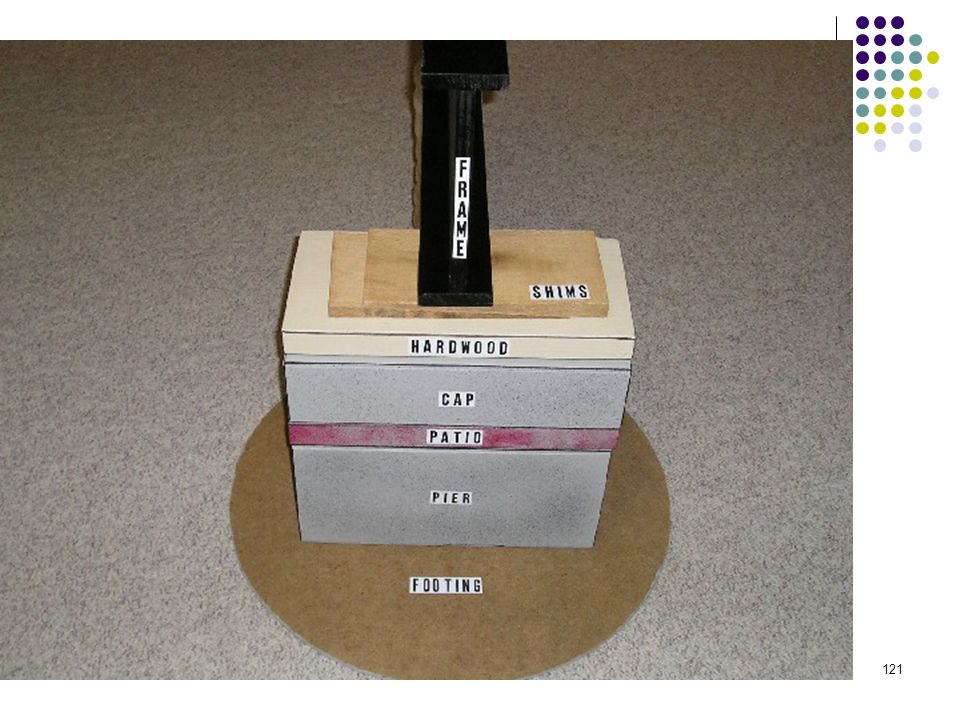
46
Pier Configuration Load bearing blocks not decorative
Nominal 8 by 8 by 16 inches Stacked with hollow cores aligned vertically When stacked side by side, each layer at right angles to preceding one Center beam/mating line supports are always required for multi-section homes

50
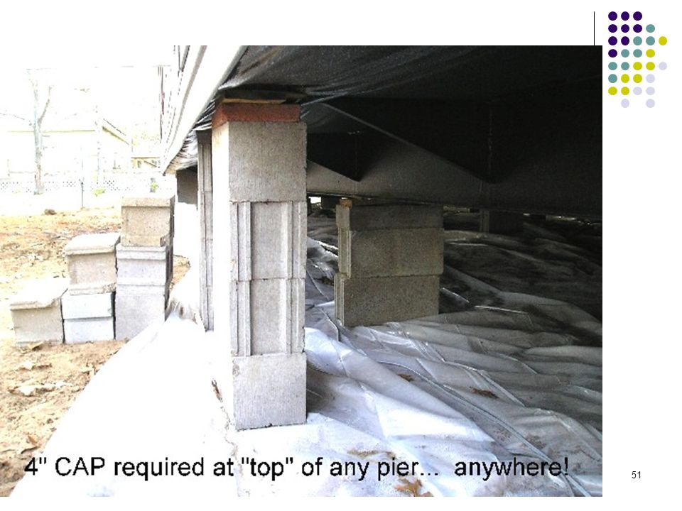
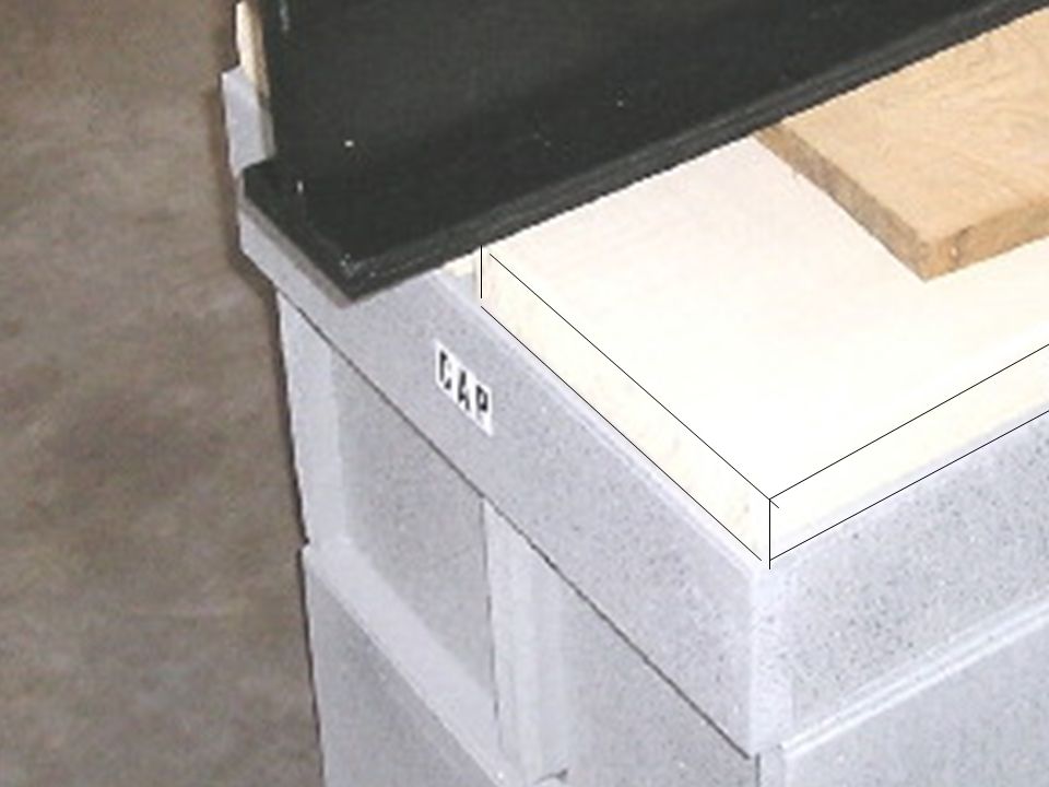
Caps Must evenly distribute loads across the capped hollow block piers
May be made of solid concrete or masonry at least 4 inches nominal thickness OR hardwood lumber at least 2 inches thick OR corrosion protected min ½ inch thick steel or other listed materials

52
Caps Must be same length and width as piers
Split caps on double stacked piers must be installed with long dimension across the joint in blocks below

53
Gaps Must be filled with one of these methods
Nominal 4 by 6 by 1 inch shims Must be used in pairs Driven tightly Must not occupy more than 1 inch of vertical space

54
Manufactured Piers Adjustable risers must not extend more than 2 inches when finally positioned

56
Clearance under Home Minimum of 12 inches between lowest member of main frame and grade under all areas of the home Comm for older homes is A minimum clearance of 12 inches shall be maintained beneath the lowest point of the main frame in the area of any utility connection. A minimum clearance of 12 inches shall also be maintained under the home for at least 75% of the home. The remainder of the home may be less than 12 inches above the ground but may not touch the ground.

57
Less than 36” Piers Permitted to constructed of open or closed cell 8 by 8 by 16 when capacity of block is not exceeded Long sides are at right angles to supported I-beam Hollow cores stacked vertically and at right angles to the footings Horizontal offsets from top to bottom not to exceed ½ inch No mortar unless instructions require

60
Piers 36 to 67” and Corner Piers
All frame piers 36 to 67” high and all corner piers over 3 block high must be double blocked No mortar unless instructions require Horizontal offsets not to exceed 1”

64
Piers over 67” Must be designed by registered professional engineer or registered architect Mortar not required unless specified

65
Perimeter support piers
Piers at mate-line supports, perimeter piers, and piers at exterior wall openings can be single open-cell or closed cell blocks to a maximum height of 54 inches Must be installed with the long dimension parallel to perimeter rail

66
Pier Support Locations
No more than 24 inches from both ends of frame No more than 120 inches center to center under the main I beam Mating line, marriage wall line, ridge beam all mean the point where sections join and they require support – Be alert to extreme weight considerations in these locations!

67
Perimeter Support Locations
Both sides of any exterior door Any side wall opening of 48 inches or more Under any load-bearing porch posts, factory installed fireplaces and wood stoves

68
Alternative to Perimeter Supports
If additional floor joists or outriggers are providing perimeter support, the sizing of piers and footers under the main chassis beam must be adjusted.

69
Footings Must be located on undisturbed soil or fill compacted to 90% of maximum relative density A footing for every pier Footing size depends on the load bearing capacity of soil, footings and piers 69

70
Footing Types Concrete types
4 inch nominal pre-cast pads meeting ASTM C with 28 day compressive strength of 1,200 psi 6-inch minimum poured in place concrete pads, slabs or ribbons with at least 28 day compressive strength of 3,000 psi 70

71
Footing Types Pressure-treated wood
Minimum 2 layers of nominal 2 inch thick pressure treated wood Single layer of nominal ¾ inch pressure treated plywood with a max size of 16 by 16 (must be rated exposure 1 or exterior sheathing PS-1-95 rated Cut ends must be field treated

72
Footing Types ABS footing pads
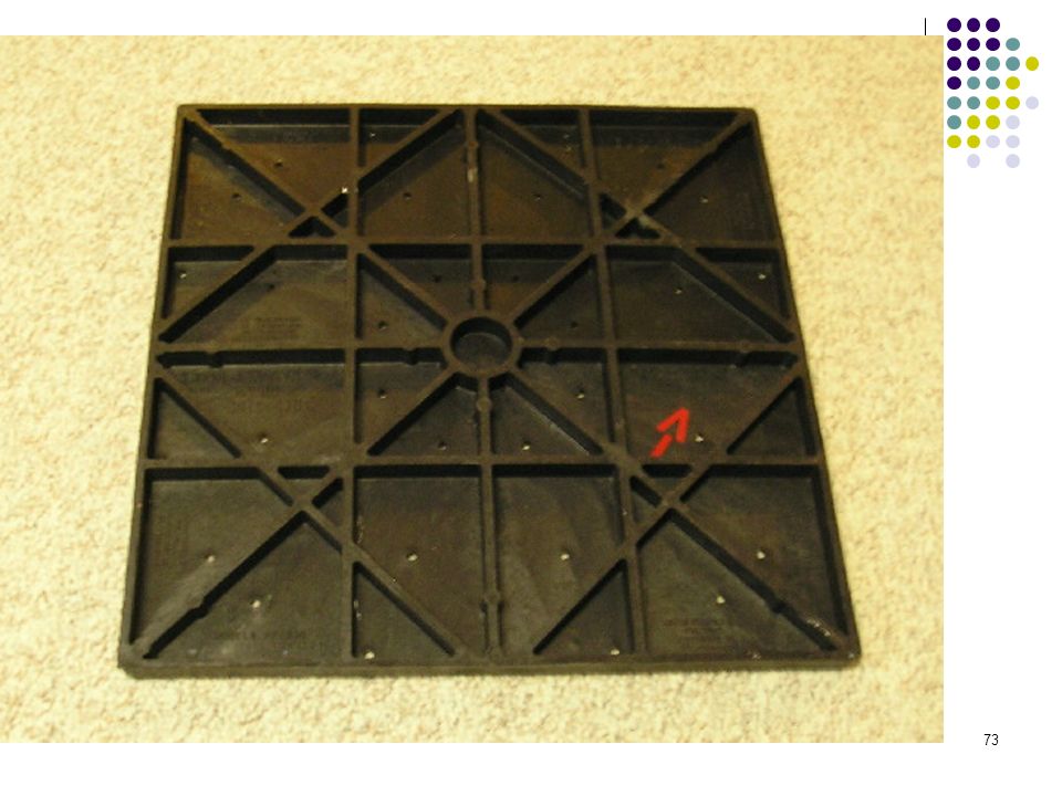
Installed according to pad manufacturer instructions and certified for use in soil classification at the site Must be listed for required load capacity

74
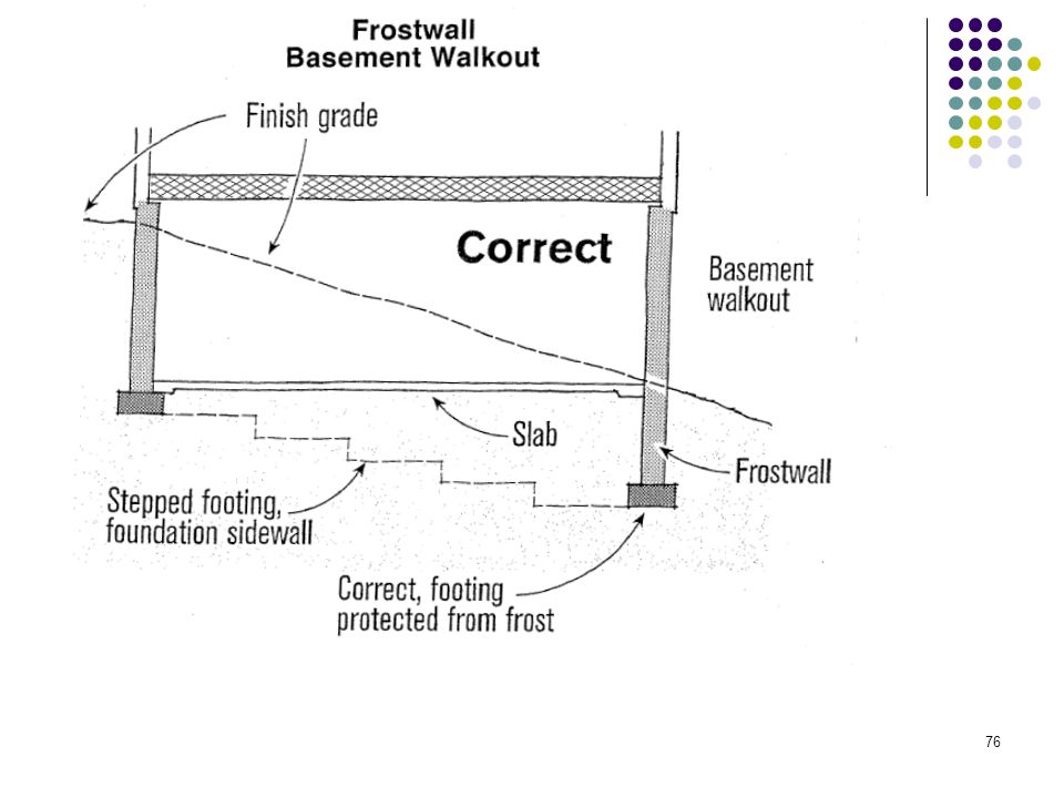
Frost Protection Frost line is 48 inches statewide as set by Commerce
Footings must be designed using methods and practices that prevent the effects of frost heave by: Conventional below the frost line footing Monolithic slab above frost line – must be designed by registered engineer or architect Insulated foundation system above frost line - must be designed by registered engineer or architect Frost line is 48 inches statewide as set by Commerce

77
Footing Sizing Table How to use the tables
Use soil bearing capacity to determine size and thickness needed

78
Anchorage After blocking and leveling, the manufactured home must be secured against the wind by an anchoring system Anchoring equipment means ties, straps, cables, turnbuckles, chains and other approved components including tensioning devices that are used to secure a manufactured home to anchor assemblies. Conventional anchors or alternative foundation system (Tie Down or Oliver Technologies type systems)
")
79
Tie Down Engineering Vector System

80
Vector System with Longitudinal Support
Note base plate and longitudinal support

81
Anchorage The anchors must be capable of meeting the loads the home was designed to withstand – see data plate Follow the anchor company’s instructions for spacing, angles, connections and so forth Install anchors to their FULL depth A diagonal anchor tie is intended to resist horizontal or shear forces, but may also resist vertical, uplift and overturning forces

82
Ground Anchors Must be listed (listed means approved)
Steel coated with zinc to not less than 0.30 oz/ft2 of surface Capable to resist a min ultimate load of 4750 lb and a working load of 3150 lbs (check listing labels)
")
83
Tie Down Straps 1 ¼ inch by in or larger steel strapping conforming to ASTM D standard Capable to resist a min ultimate load of 4750 lb and a working load of 3150 lbs (check listing labels) – Same capacity as the anchors Coated with zinc to not less than 0.30 oz/ft2 of surface
 – Same capacity as the anchors. Coated with zinc to not less than 0.30 oz/ft2 of surface.")
84
Tie Downs Maximum spacing – see the tables
See drawings for near beam and second beam methods If sidewall or over the roof, mate-line or shear wall straps are installed, they must be connected Must be augured below the frost line unless the foundation is a frost protected above frost line system

85
Tie Down Tips No long tails
Tension evenly or you might pull the home off the supports Determine if stabilizer plate is needed – See anchor manufacturer instructions Try locking clamp version

86
Tie Down Safety Issues Locate Utilities
- abandoned electrical drops is a concern - utility lineman’s gloves are recommended - Testing for power on anchor before connecting to home can be done using a simple voltage checker $5.25 worth of safety Image courtesy of Lab Safety, Janesville

87
On-site structures Each expansion room or other on-site structure must be able to support its own weight including any garage unless pre-designed by manufacturer, engineer or architect Any addition must be designed by either the home manufacturer, a registered engineer or architect

89
Optional Equipment Comfort systems (HVAC) must be installed by a licensed HVAC contractor if not factory installed Air conditioning equipment must be properly sized All heat producing equipment must be properly vented thru the skirting or exterior wall as appropriate When not installed by home manufacturer, must be installed according to the appliance manufacturer’s instructions

91
Skirting Must be weather resistant
Attached so no water is trapped between siding and trim or forced up into the wall cavity trim it is attached to All wood skirting within 6 inches of the ground must be pressure treated or be naturally resistant to decay and termites – This would include lumber and sheathing extension if any of the wood is less than 6 inches above the ground

96
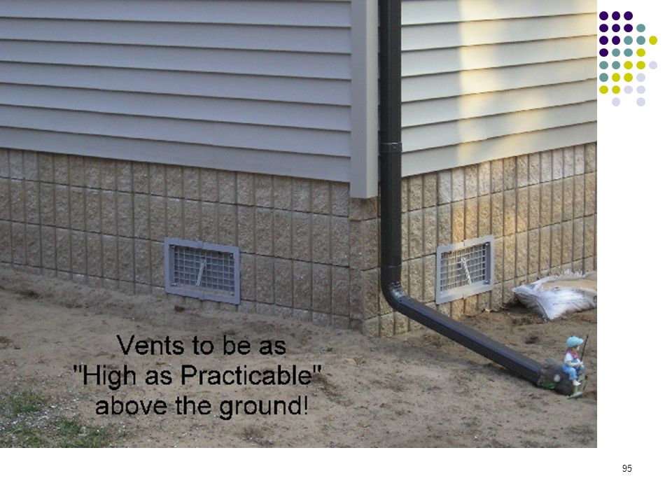
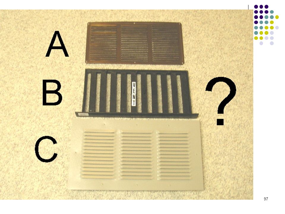
Crawlspace Venting NEW - One square foot for every 1,500 sq ft of floor area – Important – Check with your manufacturer before proceeding with reduced venting Vent openings as high as practicable Vents must located on at least two opposite sides of home Openings must be covered with a perforated corrosion and weather resistant covering to prevent rodent entry

98
Access Opening Not less than 18 wide by 24 high and not less than 3 sq ft Must be located so that any utility connections under the home are accessible

100
Dryer vents, air conditioning, & combustion air vents
Must pass through skirting to the outside This includes fireplace air inlets

101
Ductwork, Plumbing & Fuel Supplies
Manufacturer must supply instructions for proper field assembly

102
Water When local water supply pressure exceeds 80 psi, a pressure reducing value must be installed An identified and accessible shutoff value must be installed underneath or adjacent to the home Crossovers and lines must be protected from freezing Only listed for MH heat tape is permitted Water system must be inspected and tested for leaks after completion at the site. Disconnect water heater if test is air only

103
Piping support Water lines supported every 3 feet
Drain lines supported every 4 feet – See 48 inch on center max

104
Gas Supply Home design calls for system pressure of 10 to 14 inches of water column pressure (0.036 psi)
")
105
Ductwork Crossovers All ductwork connections must be sealed
Galvanized metal straps or tape and mastics listed to UL 181 A or B must be used around duct collar and secured tightly Metal straps required metal sheet screws Metal ducts must be fastened with at least 3 galvanized sheet metal screws equally spaced around the collar

106
Ductwork Max distance for duct supports is 4 feet
If straps are used they must be ½” wider than spacing of spirals in flex duct Arrange so that straps cannot slip between spirals and to prevent kinking Cannot contact ground Listed for exterior use only Crossovers outside the envelop must be insulated with proper materials In-floor or ceiling crossover connections must be sealed to prevent air leakage

107
Subpart H - Electrical Snap connections may or must be fastened to adjacent stud – CHECK instructions If a fixture is mounted on a combustible surface a limited combustible or non-combustible ring must be installed Wires connected black to black, white to white and ground to ground Test all connections

108
Smoke Alarms Additional shipped loose alarms for basement set models are typically provided by the manufacturer They may be wired to communicate with factory installed units at main floor

109
Exterior close-up Manufacturers provide instructions for joining sections. Pay particular attention to directions on fasteners The mate-line gasket must be installed following manufacturer instructions Exterior close up strips are trim that must be fastened securely and sealed with an exterior sealant

110
Before Sections are Secured
The poly sheeting used for transport must be removed completely

111
Hinged roofs and eaves May be subject to alternative construction inspections if flue penetrations are above the hinge

112
Gaps UPON COMPLETION – no gaps are permitted between structural elements PRIOR TO COMPLETION – minor gaps not exceeding one inch are permitted PROVIDED they are filed upon completion Fill gaps must be shimmed with dimensional lumber and fastener lengths used to make connections must be increased to provide adequate penetration into receiving lumber. Pay particular attention to end wall and floor completion gaps – May have marriage wall sheathing in from end wall ends

113
Close up All shipping blocking, strapping or bracing must be removed from appliances, window and doors. At a minimum, shipped loose wall panels must be installed using PVA adhesive on all framing members and fastened with 1 inch long staples or nails 6 inch on center panel edges and 12 inches on center in the field unless manufacturer directs other methods

114
Bottom Board Bottom Board is an industry term for barrier installed by the factory on the bottom of the floor system. It is for rodent control. Inspect for loosing or areas damaged by transport or installation Tears must be repaired Any missing insulation must be replaced Splits or tears must be resealed with tape or patches P traps must be checked to be sure they are well insulated and covered All repaired edges must be taped or otherwise sealed

115
Access to site The installer is responsible to ensure that transportation routing is possible and permits obtained Effective 4/01/07 disturbed soil areas of 1 acre or more at property site are subject to permits and UDC erosion control regulations (This also includes entire driveway areas!)
")
116
Gas appliances Make sure orifices match the fuel supply
Inspect vents to make sure they were not damaged in transit

117
Other UDC Issues to Watch
Site constructed elements subject to UDC Basement stairs Exterior decks, stairs and railings Garage attachments Habitable basements Egress windows for bedrooms Heating calculations for entire envelop

118
Trouble spots-Basement Stairs
Finished Stairwell Length (FSL) Headroom (Min. 6'-4") Headroom + Floor/Ceiling Depth (HFCD) Finished Stairwell Length(FSL) Unit Rise Unit Run So to solve for FSL, FSL = Unit Run x HFCD Unit Rise Floor/Ceiling Depth Max. 8" Unit Run Min. 9" Two Similar Right Triangles Maintain 6'-4" Headroom In Required 3' Long Landing
 Headroom. (Min ) Headroom + Floor/Ceiling Depth (HFCD) Finished Stairwell Length(FSL) Unit Rise Unit Run. So to solve for FSL, FSL = Unit Run x HFCD. Unit Rise. Floor/Ceiling Depth. Max. 8 Unit Run. Min. 9 Two Similar Right Triangles. Maintain 6 -4 Headroom In Required 3 Long Landing.")
125
“Structural Analysis” per Dept. of Comm.
Comm (Definitions.) (73) “Structural Analysis” is a branch of the physical sciences which uses the principles of mechanics in analyzing the impacts of loads and forces and their effect on the physical properties of materials in the form of internal stress and strain. Comm (Structural Analysis Standards.) Structural analysis shall conform to the following nationally recognized standards. ( c ) Concrete. Plain, reinforced or pre-stressed concrete construction shall conform to the following standards: · 1. ACI Standard 318, “Building Code Requirements for Reinforced Concrete”. · 2. ACI Standard 318.1, “Building Code Requirements for Structural Plain Concrete”. Comm (Frost Penetration.) · (2) Exceptions. (a) Floating slabs constructed on grade need not be installed below the minimum frost penetration line provided measures have been taken to prevent frost forces from damaging the structure. · Also, ( c ) Stoops or ramps need not be installed below the minimum frost penetration level provided measures are taken to prevent frost forces from damaging the structure.
 (73) Structural Analysis is a branch of the physical sciences which uses the principles of mechanics in analyzing the impacts of loads and forces and their effect on the physical properties of materials in the form of internal stress and strain. Comm (Structural Analysis Standards.) Structural analysis shall conform to the following nationally recognized standards. ( c ) Concrete. Plain, reinforced or pre-stressed concrete construction shall conform to the following standards: · 1. ACI Standard 318, Building Code Requirements for Reinforced Concrete . · 2. ACI Standard 318.1, Building Code Requirements for Structural Plain Concrete . Comm (Frost Penetration.) · (2) Exceptions. (a) Floating slabs constructed on grade need not be installed below the minimum frost penetration line provided measures have been taken to prevent frost forces from damaging the structure. · Also, ( c ) Stoops or ramps need not be installed below the minimum frost penetration level provided measures are taken to prevent frost forces from damaging the structure.")
126
Class Verification Certificate
Continuing Education = 8425 Password is …… If password is not on the form it won’t be processed by the state.

Similar presentations


 Grants Chapter 6.>")