Download presentation
Presentation is loading. Please wait.

1
DESIGN AND FABRICATION OF TURNING FIXTURE FOR ELBOW
Guided by, Ms.J.Jayanthi, B.E., Lecturer Presented by, G.Anandha Kumar G.Muthu thiyagarajan C.Padmanabha B.Prakash

2
ABSTRACT Pipe Elbows are widely used in industries to change the flow direction. So that in industrial power piping the elbows place a dominant roll. The edge preparation of elbows generally carried out by boring machine. It is a time consuming process so we are design a fixture by which we can do the edge preparation in lathe it self.

3
DESIGN OF TURNING FIXTURE
FOR THREE INCH ELBOW: LEG PLATE DIMENSION: Center to edge dimension = A + (D/2) We know that, Out side dia at the bevel of elbow (D) = 88.9mm Centre to face distance (A) = 114.3mm Therefore, Center to edge dimension = (88.9/2) = mm Allow machining tolerance for facing, Center to edge dimension = mm
 We know that, Out side dia at the bevel of elbow (D) = 88.9mm. Centre to face distance (A) = 114.3mm. Therefore, Center to edge dimension = (88.9/2) = mm. Allow machining tolerance for facing, Center to edge dimension = mm.")
4
Radius for block and clamp = 46mm
Contd., RADIUS CALCULATION FOR BLOCK AND CLAMP radius of curvature = D/2 = 88.9/2 = 44.5mm Allow 1.5 mm clearance, Radius for block and clamp = 46mm

5
PARTS IN THE TURNING FIXTURE
SERIAL.NO DESCRIPTION QUANTITY 01 Base plate 02 Leg 03 Weldment 04 Side plate 05 Block 06 Top clamp 07 Stud 08 Bottom plate 09 Fit bolt

6
VARIUS PARTS AND FUNCTIONS
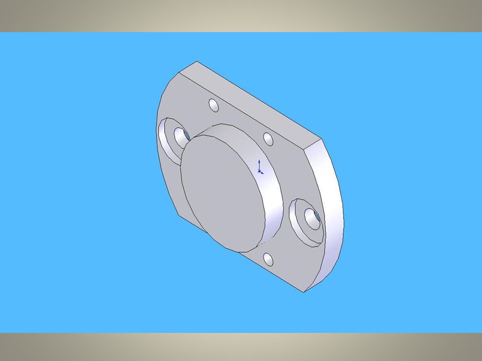
CHUCK BASE PLATE The figure shows the chuck base plate which is having mounting arrangements with Center Lathe. The dia of 78mm hub is fixed with the chuck.

8
LEG The leg, which is getting screwed with the chuck base plate and holds the job-holding device at its diameter location.

9
SIDE PLATE The side plate, which is having controlled dimensions, derived from the face to centre distance.

10
PLATE It is the drilled plate, which is having mounting arrangements for the indexing of elbow.

11
BLOCK The block is used to hold the elbow
BLOCK The block is used to hold the elbow. It is welded with the side plate.

12
STUD This is being welded with side plate. This studs aids to clamp the job with the fixture.

13
FIT BOLT The figure shows the fit locator bolt. For 24 mm length we have make M20 thread. This is used to fit the leg with the weldment. This bolt is a stepped section.

14
TOP CLAMP Clamp is also used to hold the elbow which has a calculated dia of 46mm.It is mounted over the elbow by means of a stud.

15
ADVANTAGES Time consumption for a edge preparation in horizontal boring machine is high. This fixture reduces the time up to 8minutes per a single job. Machining will be faster and level of accuracy also high. Setting time for fixing the elbow is less Optimum centre of the elbow can be maintained throughout the operation.

16
DISADVANTAGES The turning fixture is depends on the size of the elbow. So separate fixture should be designed for different elbows. This is only suitable for mass production.

17
COST ESTIMATION Cost of the material Cost of fasteners
Cost of 3” elbow Machining cost Other charges TOTAL COST OF THE PROJECT

18
CONCLUSION Thus the turning fixture for three inch elbow is designed and fabricated. The turning fixture reduces time consumption in lathe for mass production. Using this fixture edge preparation operation like grooving, facing, turning can be performed easily.

19
TURNING FIXTURE ASSEMBLED VIEW

20
Thank you

21
Queries ??

Similar presentations


 or no of.>")


