Download presentation
Presentation is loading. Please wait.

1
FILM CASSETTES & INTENSIFYING SCREENS WEEK 9
RTEC A Spring 2009 FILM CASSETTES & INTENSIFYING SCREENS WEEK 9

2
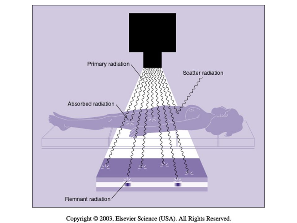
Creating the IMAGE When x-rays pass through a patient's body, three things can happen: (1) the x-ray photon is transmitted, passing through the body, interacting with the film, and producing a dark area on the film; (2) the x-ray photon is absorbed in an area of greater tissue density, producing lighter areas on the film; and (3) the x-ray photon is scattered and reaches the film causing an overall gray fog.
 the x-ray photon is transmitted, passing through the body, interacting with the film, and producing a dark area on the film; (2) the x-ray photon is absorbed in an area of greater tissue density, producing lighter areas on the film; and. (3) the x-ray photon is scattered and reaches the film causing an overall gray fog.")
4
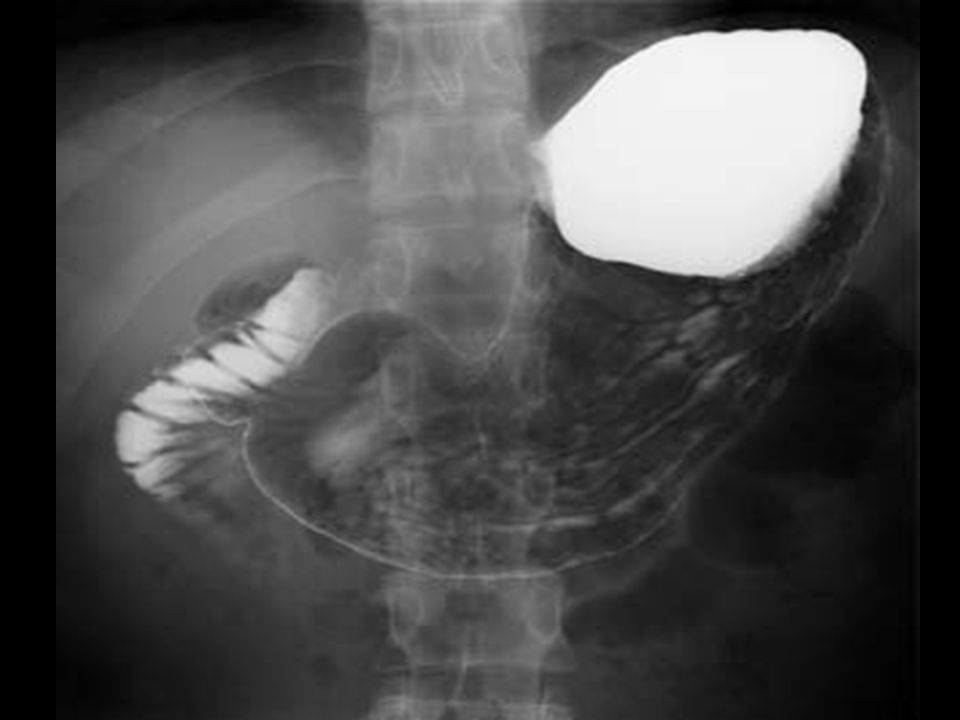
Radiographic Images AIR, CO2 , Lungs BARIUM, IODINE, Bones
RADIOLUCENT - dark on image AIR, CO2 , Lungs RADIOPAQUE - white on image BARIUM, IODINE, Bones

6
Primary Radiation exit from tube
100 % enters patient 1% exits for form image on cassette below REMNANT Radiation

7
Cassettes Cassettes serve 3 important functions:
Protect film from exposure to light Protect film from bending and scratching during use. Contain intensifying screens, keeps film in close contact to screen during exposure.

8
Image formation Remnant x-ray photons converted to light photons
Image before processing = Latent image Made visible by chemical processing = Manifest image

9
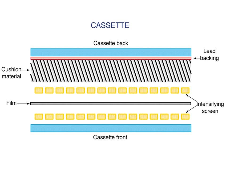
CASSETTE or FILM HOLDER
The CASSETTE is used to hold the film during examinations. It consist of front and back intensifying screens, and has a lead (Pb) backing. The cassette is light tight
 backing. The cassette is light tight.")
11
ALWAYS KEEP THE COLLIMATED AREA SMALLER THAN THE SIZE OF THE CASSETTE

12
Cassette Features - Front
Exposure side of cassette is the “front”. Has the ID blocker (patient identification) Made of radiolucent material – easily penetrated by x-rays, lightweight metal alloy or plastic material made of resin. Intensifying screen mounted to inside of front.
 Made of radiolucent material – easily penetrated by x-rays, lightweight metal alloy or plastic material made of resin. Intensifying screen mounted to inside of front.")
13
Cassette Features - Back
Back made of metal or plastic Inside back is a layer of lead foil – prevents backscatter that could fog the film Inside foil layer is a layer of padding – maintains good film/screen contact Back intensifying screen mounted on padding

14
Cardboard Cassettes Direct x-ray exposure to film required
25 to 400 times more radiation to create an image on the film BETTER DETAIL THAN FILM SCREEN (NO BLURRING OF IMAGE FROM LIGHT) ALL EXPOSURE MADE FROM X-RAY PHOTONS BIG DOSE TO THE PATEINT
 ALL EXPOSURE MADE FROM X-RAY PHOTONS. BIG DOSE TO THE PATEINT.")
15
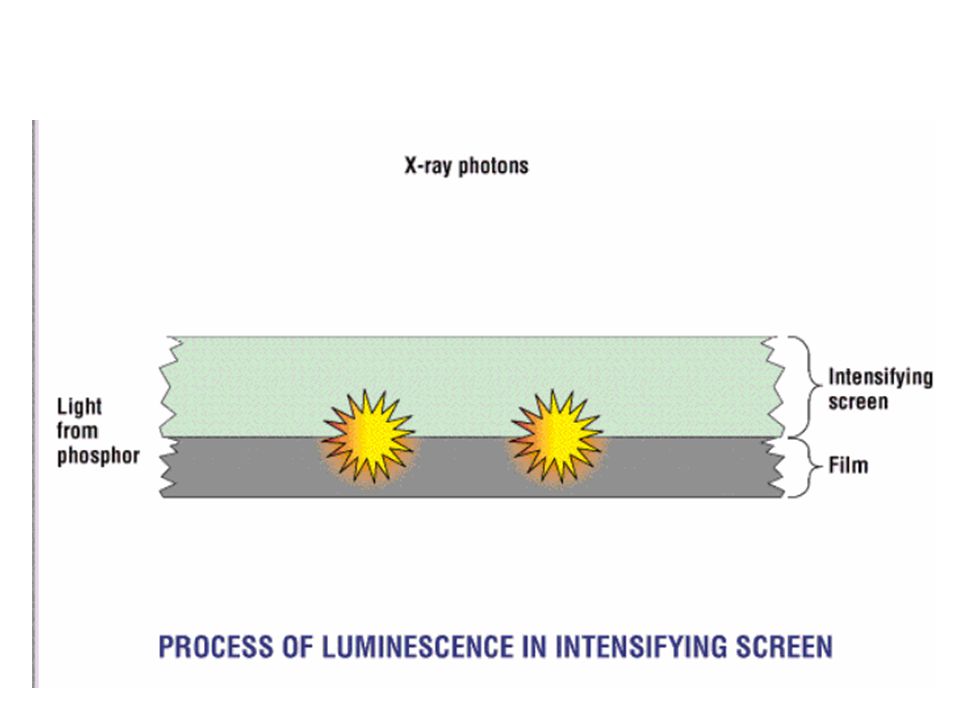
Intensifying Screens Flat surface coated with fluorescent crystals called phosphors that glow, giving off light when exposed to x-rays.

18
Image creation 1% of xray photons that leave patient
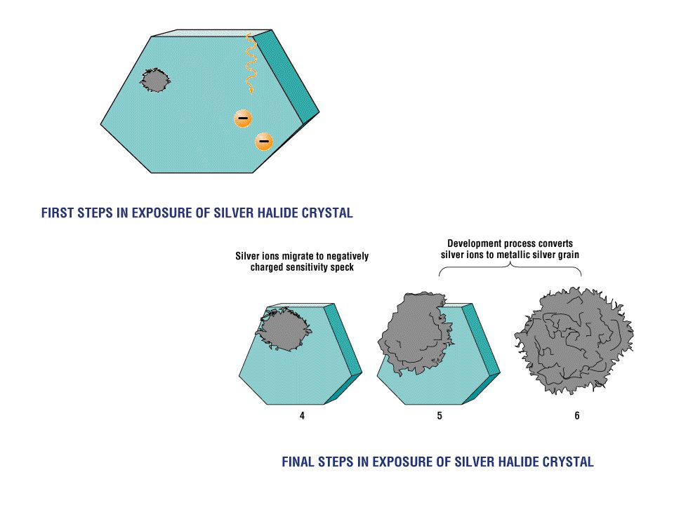
Interact with phosphors of intensifying screens 100’s of light photons created to make image on film Light photons expose silver halide crystals in the film emulsion – Turn black metallic silver after procession

19
Intensifying Screens Phosphors
RARE EARTH – (emits green light) Developed in 1980’s Most efficient – most common in use today CALCIUM TUNGSTATE (blue light) Not as efficient
 Developed in 1980’s. Most efficient – most common in use today. CALCIUM TUNGSTATE (blue light) Not as efficient.")
20
Rare Earth Screens Gadolinium Lanthanum Yttrium
Found in low abundance in nature

21
Reduce patient exposure Increase x-ray tube life
INTENSIFYING SCREENS DISADVANTAGES: less detail than direct exposure (detail better with rare earth than calcuim tungstate screens) ADVANTAGES: Reduce patient exposure Increase x-ray tube life
 ADVANTAGES: Reduce patient exposure. Increase x-ray tube life.")
23
Screen Construction Polyester plastic base – support layer
Phosphor layer – active layer Reflective layer – increases screen efficiency by redirecting light headed in other directions Protective coating

24
Intensifying screens

25
Phosphor Layer Active layer – x-ray photons converted to light photons
*Photoelectric Effect

26
Screen Speed Efficiency of a screen in converting x-rays to light is Screen Speed.

27
Screen Speed Greater efficiency = less exposure = faster
-Standard screen speed class of 100 -200 screen speed is twice as fast Speeds for routine work: 200 – 800 Speeds for high detail:

28
SCREEN SPEEDS FASTER SPEED – REDUCES PATIENT EXPOSURE
FASTER SPEED - REDUCES IMAGE DETAIL (LIGHT BLURING AROUND IMAGE)
")
29
FILM Standard Sizes in Inches 14 X 17 11 X 14 10 X 12 8 X 10 Metric:
18cm x 24cm 24cm x 30cm 30cm x 35cm 35cm x 43cm

30
X-Ray Film Film is a media that makes a permanent record of the image. Image recorded on film is caused by exposure to photons:

31
RADIOGRAPH PERMANENT RECORD MADE USING RADIATION
RADIO- RADIATION (usually x rays) GRAPH PERMANENT RECORD
 GRAPH PERMANENT RECORD.")
32
FIRST “FILM” GLASS PLATES WW 1 CELLULOSE ACETATE HIGHLY FLAMMABLE EASILY TORN RESPONSIBLE FOR MANY FIRES IN HOSPITAL BASEMENTS

33
X-ray Film cont’d Radiographic film is/was most common image receptor
Two parts: 1. Base 2. Emulsion

34
Film Construction - BASE
Made of a polyester plastic Must be clear, strong, consistent thickness Tinted pale blue or blue-gray (reduces eye strain) COATED ON 1 OR 2 SIDES WITH EMULSION
 COATED ON 1 OR 2 SIDES WITH EMULSION.")
35
Film Construction - EMULSION
Film emulsion can be on one side or both sides of base (single emulsion / double emulsion) Protective overcoat layered on top of emulsion Emulsion is a gelatin containing the film crystals
 Protective overcoat layered on top of emulsion. Emulsion is a gelatin containing the film crystals.")
36
FILM COMPOSTION SINGLE OR DOUBLE EMULSION EMULSION : GELATIN
COATED ON A BASE EMULSION : GELATIN WITH SILVER HALIDE CRYSTALS BASE: SUPPORT POLYESTER

37
Film Emulsion Made of mixture of gelatin & silver halide crystals (fluorine, chlorine, bromine, & iodine) Most x-ray film emulsions made of : silver bromide (90%) silver iodide (10%) Photographically active layer – activated by light & radiation to create image
 silver iodide (10%) Photographically active layer – activated by light & radiation to create image.")
38
X-Ray Film Cross Section

39
FILM CONSTRUCTION BASE WITH EMULSION CAN BE ON 1 (SINGLE EMULSION)
OR 2 SIDES (DOUBLE EMULSION) MUST BE MATCHED WITH 1 OR 2 SIDED INTENSIFYING SCREENS
 MUST BE MATCHED WITH 1 OR 2 SIDED INTENSIFYING SCREENS.")
40
IMAGE ON FILM SINGLE EMULSION = BETTER DETAIL
DOUBLE EMULISON = LESS DETAIL PARALLAX With double emulsion – an image is created on both emulsions – then superimposed – slight blurring of edges

41
PARALLAX – each emulsion has an image single image overlaped – edges less sharp

42
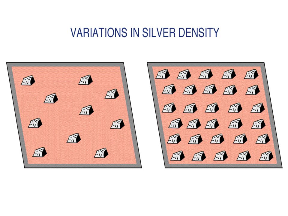
Film Characteristics Size of silver halide crystals & emulsion thickness determine speed of film and degree of resolution Speed – the response to photons Resolution – the detail seen

43
Film Speed / Crystal size
Larger crystals or Thicker crystal layer Faster response= less detail, and less exposure (chest x-ray) Finer crystals / thinner crystal layer =Slower response, greater detail, more exposure (extremity)
 Finer crystals / thinner crystal layer. =Slower response, greater detail, more exposure (extremity)")
46
LIGHT VS DARK AREAS ON FILM
DARK SPOTS – SILVER HALIDE CRYSTALS THAT HAVE BEEN EXPOSED TO PHOTONS – TURN TO BLACK METALLIC SILVER AFTER PROCESSING LIGHT AREAS – NO CRYSTALS EXPOSED – SILVER HALIDE IS WASHED AWAY WITH PROCESSING

48
FILM BIN - STORAGE

49
Film Storage Clean, dry location 40 – 60 % Humidity 70 º Fahrenheit
Away from chemical fumes Safe from radiation exposure Standing on edge Expiration date clearly visible

52
X-ray Film Sensitivity
Light X-rays Gamma Rays Gases Fumes Heat Moisture Pressure Static Electricity Age So what happens??

53
FILM FOG!!!! Unintended uniform optical density on a radiograph because of x-rays, light, or chemical contamination that reduces contrast & affects density

55
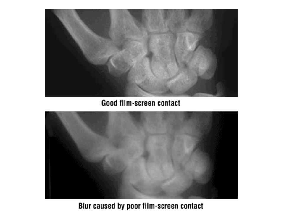
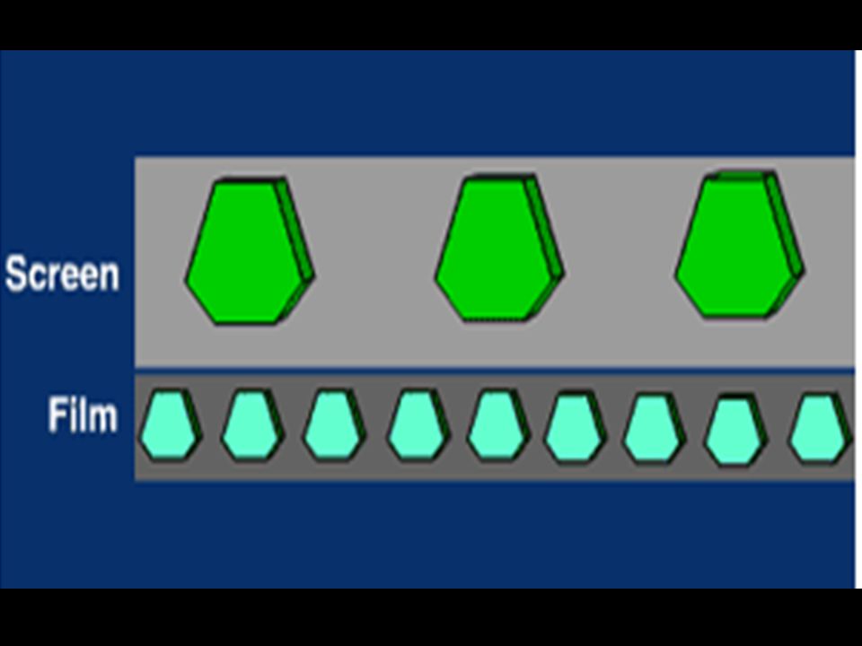
POOR SCREEN CONTACT FOAM BACKING HELSP TO PLACE INTENSIFYING SCREENS IN DIRECT CONTACT WITH THE FILM – NO GAPS IF GAPS – MORE LIGHT CAN BE EMITTED IN SPACE, CAUSING THE IMAGE TO BE OF POOR DETAIL

56
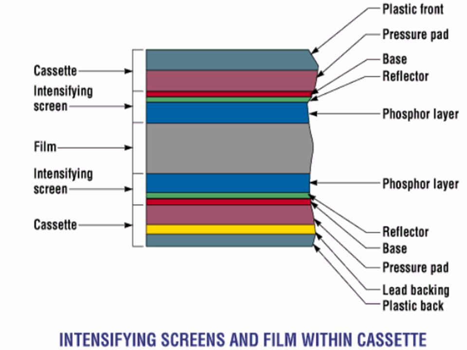
Intensifying Screen & Film Cross Section

59
Spectral Sensitivity OR SPECTRAL MATCHING Film is designed to be sensitive to the color of light emitted by the intensifying screens Blue – UV light sensitive film – CALCIUM TUNGSTATE screens Green, Yellow-Green light sensitive film - RARE EARTH screens

60
The light photons generated in the intensifying screen are emitted by phosphor crystals.
These crystals are significantly larger than the silver halide crystals in the film use of a screen reduces image sharpness somewhat Some examinations requiring extremely fine detail use screens with small crystals.

63
Questions?

Similar presentations