Download presentation
Presentation is loading. Please wait.

1
electronics fundamentals
circuits, devices, and applications THOMAS L. FLOYD DAVID M. BUCHLA Chapter 14 - Transformers

2
Mutual Inductance When two coils are placed close to each other:
a changing flux in one coil will cause an induced voltage in the second coil. Electrical isolation – condition in which two circuits have no common conductive path. Mutual inductance (LM) determines the amount of voltage induced in the second coil based on the amount of current in the first coil.
 determines the amount of voltage induced in the second coil based on the amount of current in the first coil.")
3
Mutual Inductance

4
Mutual Inductance k = the coefficient of coupling (dimensionless)
L1, L2 = inductance of each coil (Henry) The coefficient of coupling depends on: orientation of the coils to each other, their proximity, and if they are on a common core. The coefficient of coupling is a measure of how well the coils are linked; it is a number between 0 and 1. - Flux (Wb)
 The coefficient of coupling depends on: orientation of the coils to each other, their proximity, and. if they are on a common core. The coefficient of coupling is a measure of how well the coils are linked; it is a number between 0 and 1. - Flux (Wb)")
5
Example 1: Two coils are wound on a single core, and the
Coefficient of coupling is The inductance of coil 1 is 10µH, and the inductance of coil 2 is 15µH. What is Lm? Example 2: Determine the coefficient of coupling when LM = 2µH, L1 = 16µH, L2 = 4µH.

6
Basic Transformer Transformer
Electrical device constructed of two or more coils of wire (windings) Electromagnetically coupled to each other With a mutual inductance to transfer power from one coil to the other coil Schematic symbols indicate the type of core. Small power transformer Air core Ferrite core Iron core
 Electromagnetically coupled to each other. With a mutual inductance to transfer power from one coil to the other coil. Schematic symbols indicate the type of core. Small power transformer. Air core. Ferrite core. Iron core.")
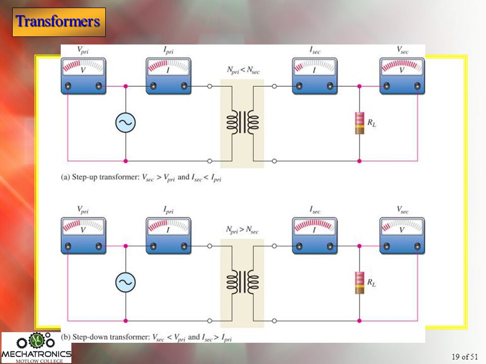
7
Basic Transformer

8
Basic Iron Core Transformer
Core Type - Easy to insulate Shell Type – higher core flux thus less turns are required

9
Transformers with cylindrical-shaped cores.
Usually used for high frequency applications

10
Some common types of transformers

11
Turns ratio Ratio of turns in the secondary winding (Nsec) to the number of turns in the primary winding (Npri) n = turns ratio Nsec = number of secondary windings Npri = number of primary windings * Based on the IEEE dictionary definition for electronics power transformers. Most transformers are not marked with turns ratio. A transformer has 800 turns on the primary and a turns ratio of How many turns are on the secondary? 200

12
Direction of windings Determines the polarity of the voltage across the secondary winding with respect to the voltage across the primary. Phase dots are sometimes used to indicate polarities. Phase Dots In phase Out of phase

13
Step-up and Step-down transformers
For any transformer: The ratio of secondary voltage (Vsec) to primary voltage (Vpri) is equal to the ratio of the number of turns in the secondary winding (Nsec) to the number of turns in the primary winding (Npri), n = turns ratio
 to primary voltage (Vpri) is equal to the ratio of the number of turns in the secondary winding (Nsec) to the number of turns in the primary winding (Npri), n = turns ratio.")
14
Step-up and step-down transformers
In a step-up transformer, the secondary voltage is greater than the primary voltage and n > 1. In a step-down transformer, the secondary voltage is less than the primary voltage and n < 1. 120 Vrms Vpri What is the secondary voltage? 4:1 30 Vrms ? What is the turns ratio? 0.25

15
Isolation transformers
A special transformer with a turns ratio of 1 is called an isolation transformer. Because the turns ratio is 1, the secondary voltage is the same as the primary voltage ac is passed from one circuit to another. The isolation transformer breaks the dc path between two circuits while maintaining the ac path. The dc is blocked by the transformer, because magnetic flux does not change with dc.

16
Coupling transformers
Special type of Isolation transformer used to pass a higher frequency signal from one stage to another. are configured with a resonant circuit on the primary and the secondary.

17
Ppri must always equal Psec
Current Transformers cannot increase the applied power. If the secondary voltage is higher than the primary voltage, then the secondary current must be lower than the primary current. If the secondary voltage is less than the primary voltage, then the secondary current must be higher than the primary current. Ppri=VpriIpri Ideally Psec=VsecIsec Ppri must always equal Psec

18
Current The ideal transformer does not dissipate power.
Power delivered from the source is passed on to the load by the transformer. The ideal transformer turns ratio equation for current is Notice that the primary current is in the numerator.

20
Reflected resistance A transformer changes both the voltage and current on the primary side to different values on the secondary side. The load resistance appears to the primary side of the transformer as a resistance (Rpri). Rpri will not necessarily equal RL. RL is “reflected” into the primary side as determined by the n; known as Reflected Resistance.
. Rpri will not necessarily equal RL. RL is reflected into the primary side as determined by the n; known as Reflected Resistance.")
21
Reflected resistance If you “look” into the primary side of the circuit, you see an effective load that is changed by the reciprocal of the turns ratio squared. You see the primary side resistance, so the load resistance is effectively changed. RL Step-up transformer - Rpri<RL Step-down transformer - Rpri>RL

22
Matching Transformers
Impedance (Z) Opposition to current flow in ac circuits Impedance matching Used to show that the source and load resistances are the same Impedance matching transformer Matches a load resistance to the internal source resistance ( maximum power is transferred to the load). Rint Impedance matching transformers are designed for a wider range of frequencies than power transformers, hence tend to be not ideal. RL Vs Impedance matching transformer
 Opposition to current flow in ac circuits. Impedance matching. Used to show that the source and load resistances are the same. Impedance matching transformer. Matches a load resistance to the internal source resistance ( maximum power is transferred to the load). Rint. Impedance matching transformers are designed for a wider range of frequencies than power transformers, hence tend to be not ideal. RL. Vs. Impedance matching transformer.")
23
Matching Transformers

24
An unbalanced signal is one that is referenced to ground.
Impedance matching Balun (short for balanced-unbalanced) transformer: Used to match a balanced line to an unbalanced line and vice-versa (hence the name balun). A balanced signal is composed of two equal-amplitude signals that are 180o out-of-phase. An unbalanced signal is one that is referenced to ground.
 transformer: Used to match a balanced line to an unbalanced line and vice-versa (hence the name balun). A balanced signal is composed of two equal-amplitude signals that are 180o out-of-phase. An unbalanced signal is one that is referenced to ground.")
25
Impedance matching Common application of a balun:
Matching a balanced dipole antenna to a coax line. Makes the conversion from a balanced line to an unbalanced line, Matches two different impedances. 300 W A dipole antenna of 300 W matched to a 75 W coax. 75 W

26
Non-ideal transformers
Operational losses occur due to: Winding resistance (causing power to be dissipated in the windings.) Hysteresis loss (due to the continuous reversal of the magnetic field.) Core losses due to circulating current in the core (eddy currents). Winding capacitance that has a bypassing effect for the windings. Flux leakage where boundary flux from the primary that does not link to the secondary
 Hysteresis loss (due to the continuous reversal of the magnetic field.) Core losses due to circulating current in the core (eddy currents). Winding capacitance that has a bypassing effect for the windings. Flux leakage where boundary flux from the primary that does not link to the secondary.")
27
Flux leakage in a practical transformer.

28
Power Ratings The power-handling capacity of a transformer is dependent upon its ability to dissipate heat. If the heat can safely be removed, the power-handling capacity of the transformer can be increased. This is sometimes accomplished by immersing the transformer in oil, or by the use of cooling fins or both. The power-handling capacity of a transformer is measured in either the volt-ampere unit or the watt unit.

29
Transformer efficiency
The efficiency of a transformer is the ratio of power delivered to the load (Pout) to the power delivered to the primary (Pin). What is the efficiency of the transformer? 20 mA Vpri RL 100 W 15 Vrms 120 Vrms
 to the power delivered to the primary (Pin). What is the efficiency of the transformer 20 mA. Vpri. RL. 100 W. 15 Vrms. 120 Vrms.")
30
Transformer efficiency
What is the efficiency of the transformer? 20 mA Vpri RL 100 W 15 Vrms 120 Vrms 94%

31
Example 2 Example 2: You have a transformer that’s primary power is 150W. If 10.5 W are dissipated in the winding resistances, what is the output power to the load, neglecting any other losses? What is the efficiency of the above transformer?

32
Tapped and multiple-winding transformers
It is possible to use multiple taps (connection points) on a transformer to achieve different voltage ratings. Can be either on the primary side or the secondary side or both. Secondary with center-tap Primary with multiple-windings
 on a transformer to achieve different voltage ratings. Can be either on the primary side or the secondary side or both. Secondary with center-tap. Primary with multiple-windings.")
33
Tapped and multiple-winding transformers

34
Tapped and multiple-winding transformers
Different taps, on the primary side, determine the voltage delivered to the customer. The center-tapped secondary allows household wiring to select either 120 V or 240 V.

35
Tapped and multiple-winding transformers

36
Three-phase transformers
Three-phase power is used for power transmission and industrial applications. Voltages in a three-phase system can be transformed with three identical single phase transformers or one three-phase transformer.

37
Three-phase transformers
Three-phase transformers are wired in either a wye or a delta configuration or a combination of both. This transformer is a wye-to-delta configuration, which is generally used in step down cases. The delta-wye (not shown) is generally used in step up cases. Vpri Vsec
 is generally used in step up cases. Vpri. Vsec.")
38
Three-phase transformer combinations
Delta to Wye Delta to Delta Wye to Delta Wye to Wye

39
Connections for a delta-to-wye transformer
Connections for a delta-to-wye transformer. The primary windings are designated Apri, Bpri and Cpri; the secondary windings are designated Asec, Bsec, and Csec. Vpri Vsec

40
Converting three-phase utility voltages to single-phase residential voltages.

41
For any line-to-neutral voltage 3-phase system, the line-to-line voltage is sqrt(3) [or1.73] times line-to-neutral voltage. This comes from the fact that the 3 voltages are at 120° from each other. The sqrt(3) comes from sin(0°)+sin(120°)+sin(240°). Then 277 x 1.73 = 480; 120 x 1.73 = 208; etc. For a 2-phase (or what is called "single-phase-3wire" system) the voltage would be 120 v from one hot to neutral and 240 v between the two hots (each hot is 180° from the other). Thus a 240 v is usually (and incorrectly) referred to as 220 v.
![For any line-to-neutral voltage 3-phase system, the line-to-line voltage is sqrt(3) [or1.73] times line-to-neutral voltage.](http://slideplayer.com/slide/5674107/18/images/41/For+any+line-to-neutral+voltage+3-phase+system%2C+the+line-to-line+voltage+is+sqrt%283%29+%5Bor1.73%5D+times+line-to-neutral+voltage..jpg "This comes from the fact that the 3 voltages are at 120° from each other. The sqrt(3) comes from sin(0°)+sin(120°)+sin(240°). Then 277 x 1.73 = 480; 120 x 1.73 = 208; etc. For a 2-phase (or what is called single-phase-3wire system) the voltage would be 120 v from one hot to neutral and 240 v between the two hots (each hot is 180° from the other). Thus a 240 v is usually (and incorrectly) referred to as 220 v.")
42
Selected Key Terms Mutual inductance Transformer Primary winding
Secondary winding The inductance between two separate coils, such as in a transformer. An electrical device constructed of two or more coils that are magnetically coupled to each other so that there is mutual inductance from one coil to the other. The input winding of a transformer; also called primary. The output winding of a transformer; also called secondary.

43
Selected Key Terms Magnetic coupling
Turns ratio Reflected resistance Impedance matching The magnetic connection between two coils as a result of the changing magnetic flux lines of one coil cutting through the second coil. The ratio of the turns in the secondary winding to the turns in the primary winding. The resistance of the secondary circuit reflected into the primary circuit. A technique used to match a load resistance to a source resistance in order to achieve maximum transfer of power.

44
Quiz 1. The measurement unit for the coefficient of coupling is a. ohm
b. watt c. meter d. dimensionless

45
Quiz 2. A step-up transformer refers to one in which
the voltage across the secondary is higher than the primary. the current in secondary is higher than the primary. the power to the load is higher than deleivered to the primary. all of the above.

46
Quiz 3. An isolation transformer a. blocks both ac and dc.
b. blocks ac but not dc. c. blocks dc but not ac. d. passes both ac and dc.

47
Quiz 4. If the current in the secondary is higher than in the primary, the transformer is a a. a step-up transformer. b. an isolation transformer. c. a step-down transformer. d. not enough information to tell.

48
Quiz 5. An ideal transformer has a. no winding resistance.
b. no eddy current loss. c. power out = power in. d. all of the above.

49
Quiz 6. Assume a step-down transformer is used between a source and a load. From the primary side, the load resistance will appear to be a. smaller. b. the same. c. larger.

50
Quiz 7. A transformer that can deliver more power to the load than it receives from the source is a(n) a. step-up type. b. step-down type. c. isolation type. d. none of the above.

51
Quiz 8. Generally, the purpose of an impedance matching transformer is to a. make the load voltage appear to be the same as the source voltage. b. make the load resistance appear to be the same as the source resistance. c. make the load current appear to be the same as the source current. d. provide more power to the load than is delivered from the source.

52
Quiz 9. A type of transformer that tends to not be ideal because it is designed for a good frequency response is a a. step-up type. b. step-down type. c. isolation type. d. impedance matching type.

53
Quiz 10. A transformer that could be used for 110 V or 220 V operation is a a. multiple-winding type. b. center-tapped type. c. isolation type. d. all of the above.

54
Quiz Answers: 1. d 2. a 3. c 4. c 5. d 6. c 7. d 8. b 9. d 10. a

Similar presentations


 a voltage by passing a wire through a magnetic.>")


