Download presentation
Presentation is loading. Please wait.

1
Digital Logic Design Lecture 19

2
Announcements Homework 6 due Thursday 11/6 Recitation quiz on Monday, 11/10 – Will cover material from lectures 18,19,20 Change in Instructor Office Hours: – Tuesday 10am-11am – Thursday 11am-12pm

3
Agenda Last time: – Binary Adders and Subtracters (5.1, 5.1.1) – Carry Lookahead Adders (5.1.2, 5.1.3) This time: – Decimal Adders (5.2) – Comparators (5.3) – Decoders (5.4) – Encoders (5.5) – Multiplexers (5.6)
 – Carry Lookahead Adders (5.1.2, 5.1.3) This time: – Decimal Adders (5.2) – Comparators (5.3) – Decoders (5.4) – Encoders (5.5) – Multiplexers (5.6)")
4
Decimal Adders 8421 weighted coding scheme or BCD Code Decimal DigitBCD 00000 10001 20010 30011 40100 50101 60110 70111 81000 91001 Forbidden codes: 1010, 1011, 1100, 1101, 1110, 1111

5
Decimal Adder

6
Comparing Binary and BCD Sums Decimal SumK 0-9 100101010000 110101110001 120110010010 130110110011 140111010100 150111110101 161000010110 171000110111 181001011000 191001111001 ---------Same-----------

7
Decimal Adder

8
A single-decade BCD Adder

9
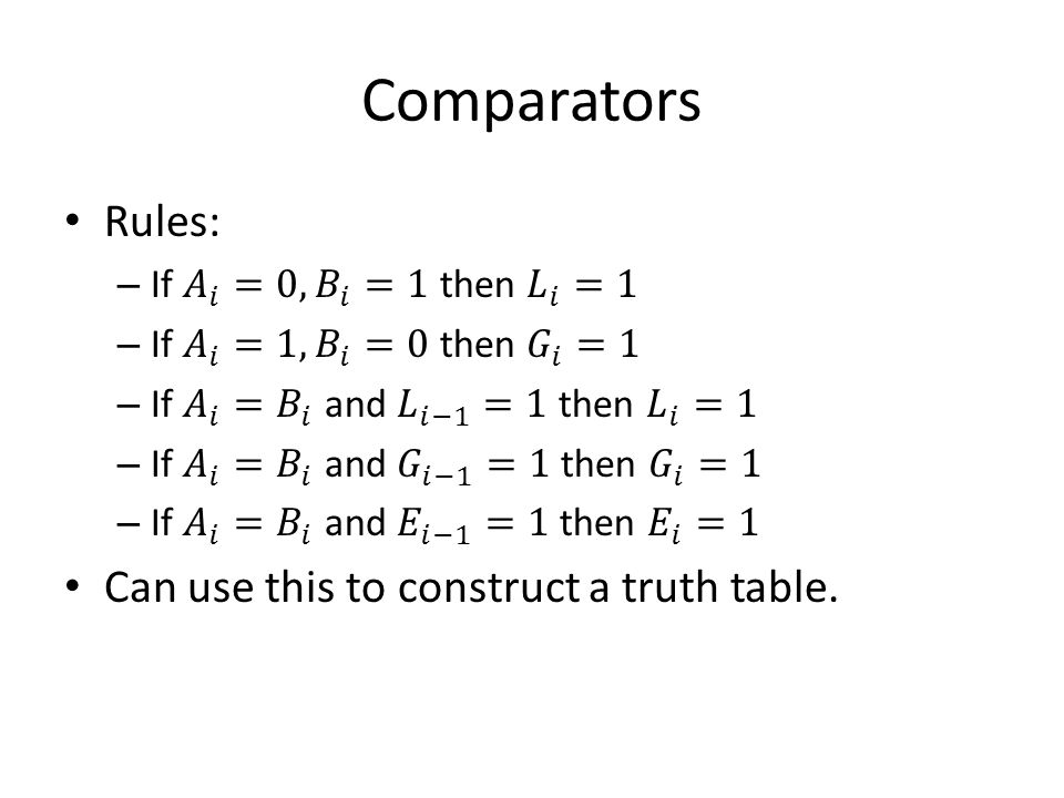
Comparators Compare the magnitude of two binary numbers for the purpose of establishing whether one is greater than, equal to, or less than the other. A comparator makes use of a cascade connection of identical subnetworks similar to the case of the parallel adder.

10
Comparators

16
Decoder

17
Realization Logic Diagram Truth Table Symbol

18
Decoder Input combinations can be regarded as binary numbers with the consequences that the j-th output line is at logic-1 for j = 0, 1,.., 7 only when input combination j is applied.

19
Other types of Decoders

20
Logic Design Using Decoders

21
Minterms using OR Gates

22
Minterms using NOR Gates

23
Implementing a Decoder using NAND Logic Diagram Truth Table Symbol

24
Minterms using AND gates

25
Decoders with an Enable Input Logic Diagram Truth Table Symbol

26
Decoders with enable inputs When disabled, all outputs of the decoder can either be at logic-0 or logic-1. Enable input provides the decoder with additional flexibility. Idea: data is applied to the enable input. Process is known as demultiplexing. Enable inputs are useful when constructing larger decoders from smaller decoders. Data

27
Constructing Larger Decoders

28
Encoders

30
Priority Encoder

Similar presentations


 Device Selection: Generates.>")
 represent Binary index of.>")


 Outputs (2 n, numbered.>")