Download presentation
Presentation is loading. Please wait.

1
Verilog Lab This presentation includes some material that is selected from BUCKNELL VERILOG HANDBOOK. Instructor: Dr. Charles Liu Prepared by John Ren Modified 5/13/04

2
Verilog Objective. Verilog and HDL.Structural-level modeling and simulation Behavioral modeling and simulation Timing specification Stimulus and control specification Response generation and verification Interactive debugging Achieving optimal performance issues Verilog environment

3
Verilog Verilog is one of the two major Hardware Description Languages(HDL) used by hardware designers in industry and academia. VHDL is another one Verilog is easier to learn and use than VHDL Verilog is C-like. VHDL is very Aad-like. Verilog HDL allows a hardware designer to describer designs at a high level of abstraction such as at the architectural or behavioral level as well as the lower implementation levels(i.e., gate and switch levels).
..")
4
Why use Verilog HDL Digital system are highly complex. Verilog language provides the digital designer a software platform. Verilog allow user to express their design with BEHAVIORAL CONSTRUCTS. A program tool can convert the verilog program to a description that was used to make exactly chip, like VLSI.

5
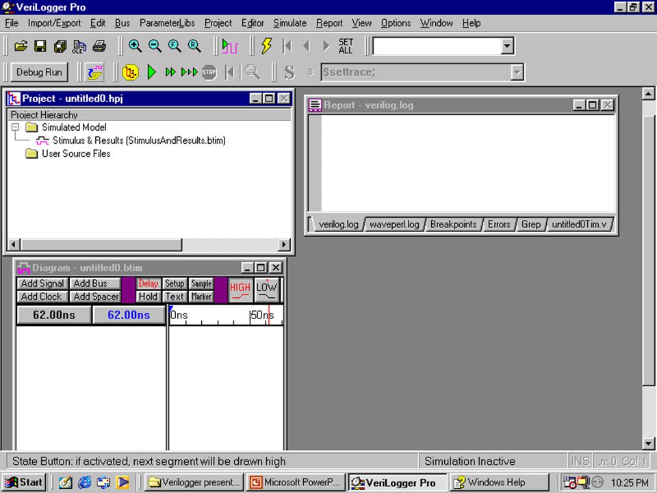
Using Verilogger Pro V9.0 Evaluation Version. enter the window of Verilogger Start Program SynaptiCad Verilogg er Pro..

6
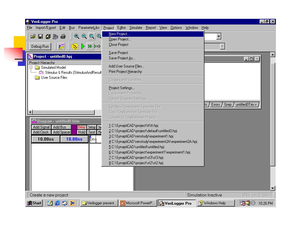
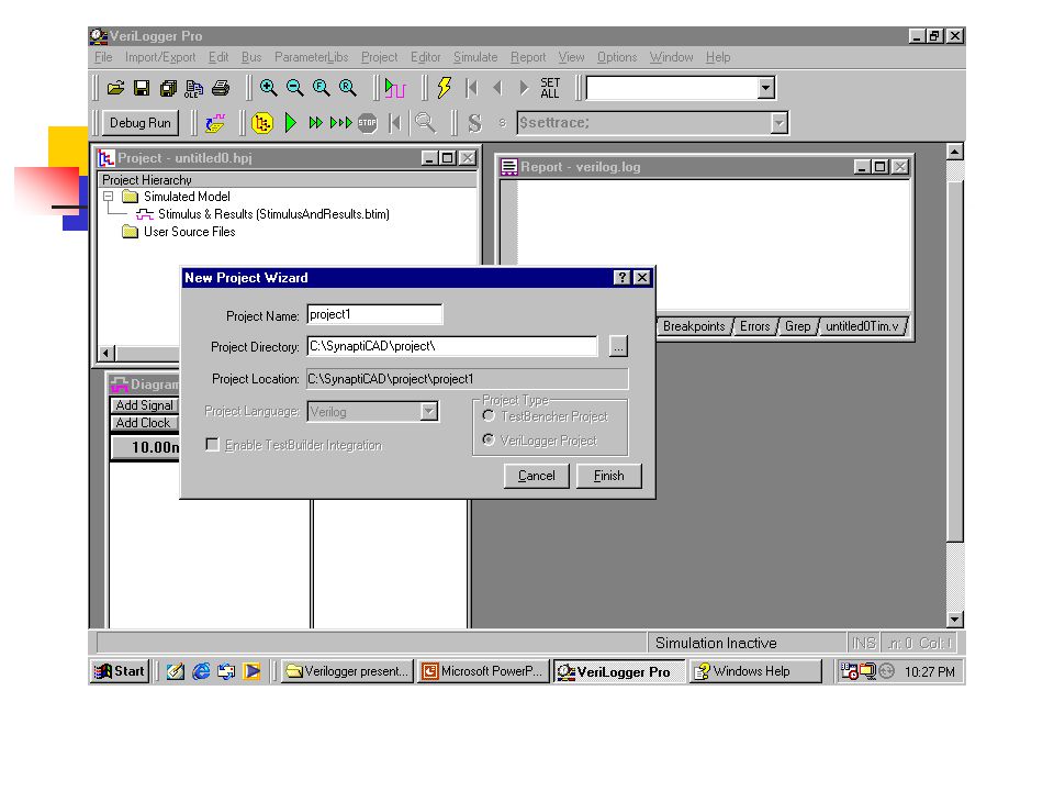
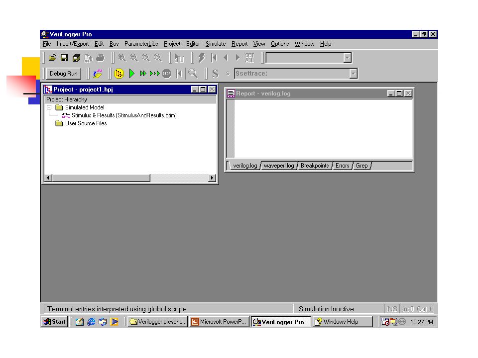
How to build a new project Project] [New Project] Click Menu [ Project] [New Project] enter the conversation window. Enter the Project Name. default: untitled.hpj. *.hpj Enter the Project Directory C:\SynaptiCAD\project\ Or others..Click the [Finish] to close the window.
![How to build a new project Project] [New Project] Click Menu [ Project] [New Project] enter the conversation window.](http://images.slideplayer.com/16/5125128/slides/slide_6.jpg "Enter the Project Name. default: untitled.hpj. *.hpj Enter the Project Directory C:\SynaptiCAD\project\ Or others..Click the [Finish] to close the window..")
7
Other menus of [Project] [Open Project] [Open Project] [Close Project] [Close Project] [Save Project] [Save Project] [Save Project as] [Save Project as] [Add User Source Files] [Add User Source Files] all the user source used by this project. all the user source used by this project. Project setting Project setting Print Project Hierarchy Print Project Hierarchy
![Other menus of [Project] [Open Project] [Open Project] [Close Project] [Close Project] [Save Project] [Save Project] [Save Project as] [Save Project as] [Add User Source Files] [Add User Source Files] all the user source used by this project.](http://images.slideplayer.com/16/5125128/slides/slide_7.jpg "all the user source used by this project. Project setting Project setting Print Project Hierarchy Print Project Hierarchy.")
8
Verilogger Editor Use the Verilogger Editor to build a program. In the Verilogger Window: click [Editor] [New HDL file] pop up a editor window for you.. Others Menu in the [Editor] same as Menu[Project]

9
Lexical Convention Lexical convention are close to C++. Comment // to the end of the line. /* to */ across several lines. Keywords are lower case letter. the language is case sensitive

10
Lexical Convention Numbers are specified in the traditional form or below. Size: contains decimal digitals that specify the size of the constant in the number of bits. Base format: is the single character ‘ followed by one of the following characters b(binary),d(decimal),o(octal),h(hex). Number: legal digital.
,d(decimal),o(octal),h(hex). Number: legal digital..")
11
Lexical Convention Example : 347 // decimal number 4 ’ b101 // 4- bit binary number 0101 2 ’ o12 // 2-bit octal number 5 ’ h87f7 // 5-bit hex number h87f7 2 ’ d83 // 2-bit decimal number String in double quotes “ this is a introduction ”

12
Lexical Convention Operator are one, two, or three characters and are use in the expressions. just like C++. Identifier: specified by a letter or underscore followed by more letter or digits, or signs. identifier can up to 1024 characters

13
Program structure Structure module ( ); endmodule. Module name an identifier that uniquely names the module.. Port list a list of input, inout and output ports which are used to other modules.

14
Program structure. Declares section specifies data objects as registers, memories and wires as well as procedural constructs such as functions and tasks.. Module items initial constructs always constructs assignment ……………….

15
Test Module structure module ; // Data type declaration // Data type declaration // Instantiate module ( call the module that is going to be tested) // Instantiate module ( call the module that is going to be tested) // Apply the stimulus // Apply the stimulus // Display results // Display results endmodule
 // Instantiate module ( call the module that is going to be tested) // Apply the stimulus // Apply the stimulus // Display results // Display results endmodule")
16
Example of gate NAND Truth Table in1 in2 out 0 0 1 0 1 1 1 0 1 1 1 0

17
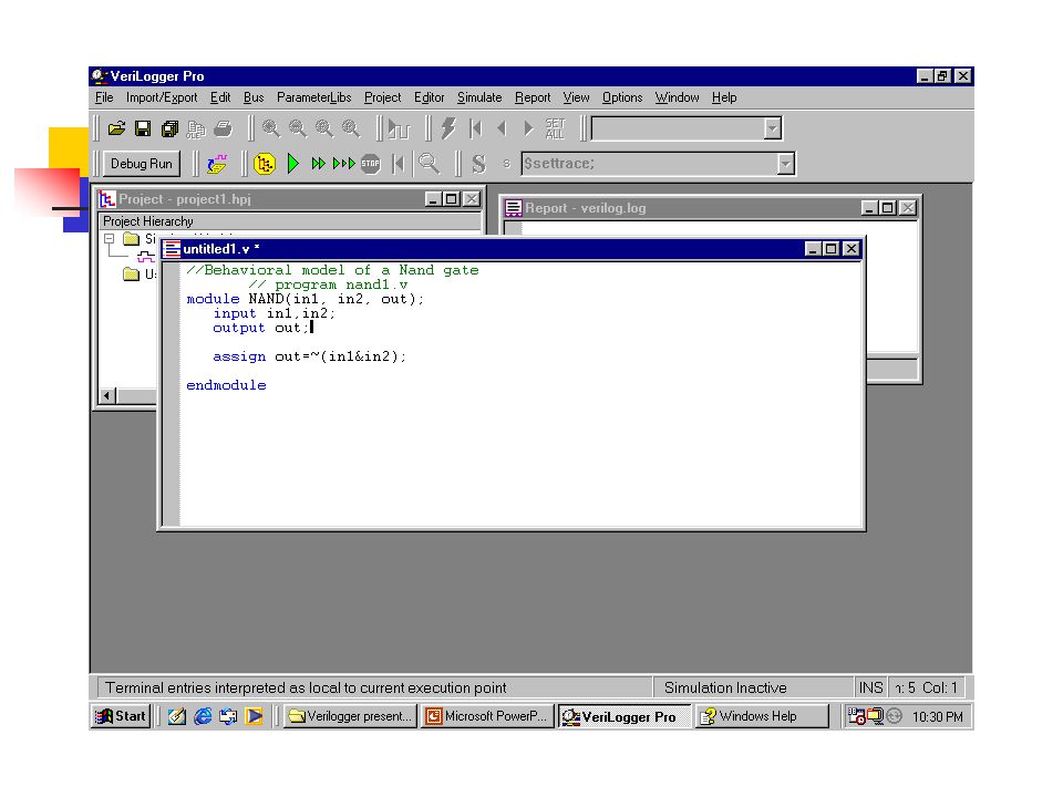
Example of gate NAND Behavioral model of a Nand gate //Behavioral model of a Nand gate // program nand1.v module NAND(in1, in2, out); input in1,in2; output out; assign out=~(in1&in2); endmodule
; input in1,in2; output out; assign out=~(in1&in2); endmodule")
18
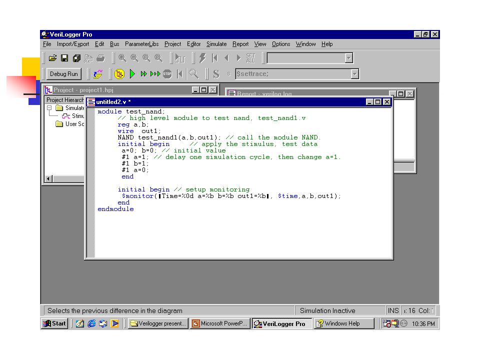
Example of gate NAND Test module test_nand for the nand1.v module test_nand; // high level module to test nand, test_nand1.v reg a,b; wire out1; NAND test_nand1(a,b,out1); // call the module NAND. initial begin // apply the stimulus, test data a=0; b=0; // initial value #1 a=1; // delay one simulation cycle, then change a=1. #1 b=1; #1 a=0; #1; end initial begin // setup monitoring $monitor( “ Time=%0d a=%b b=%b out1=%b ”, $time,a,b,out1); end endmodule
; end endmodule.")
19
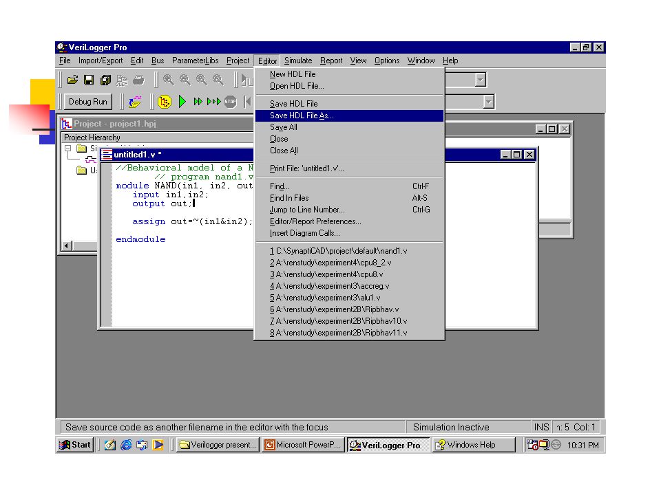
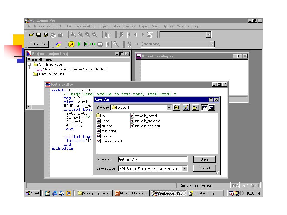
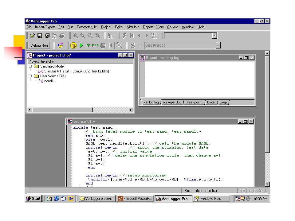
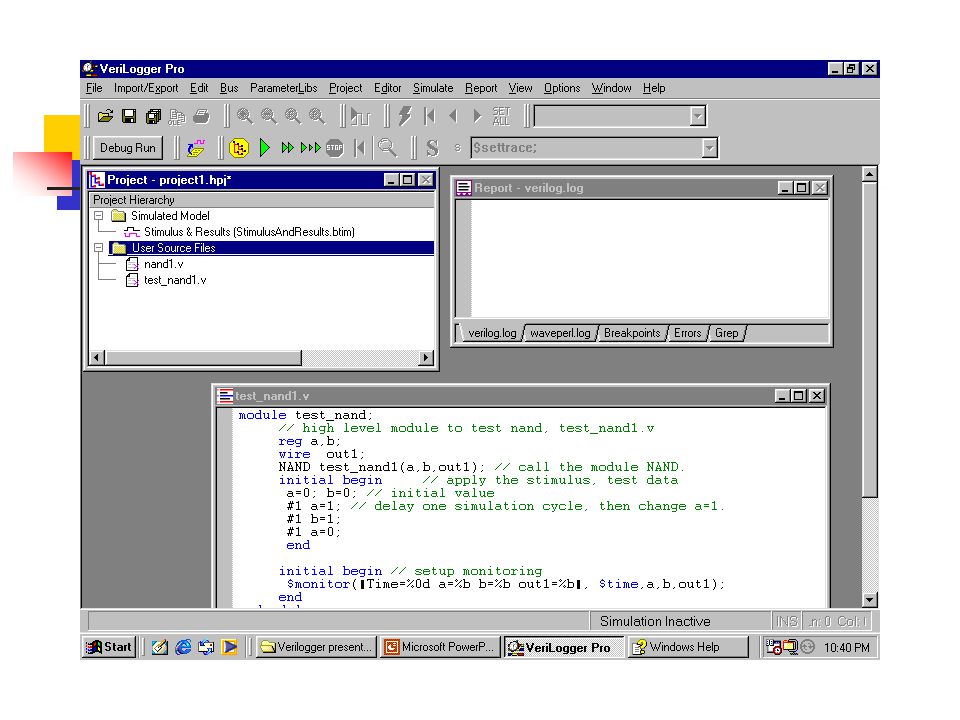
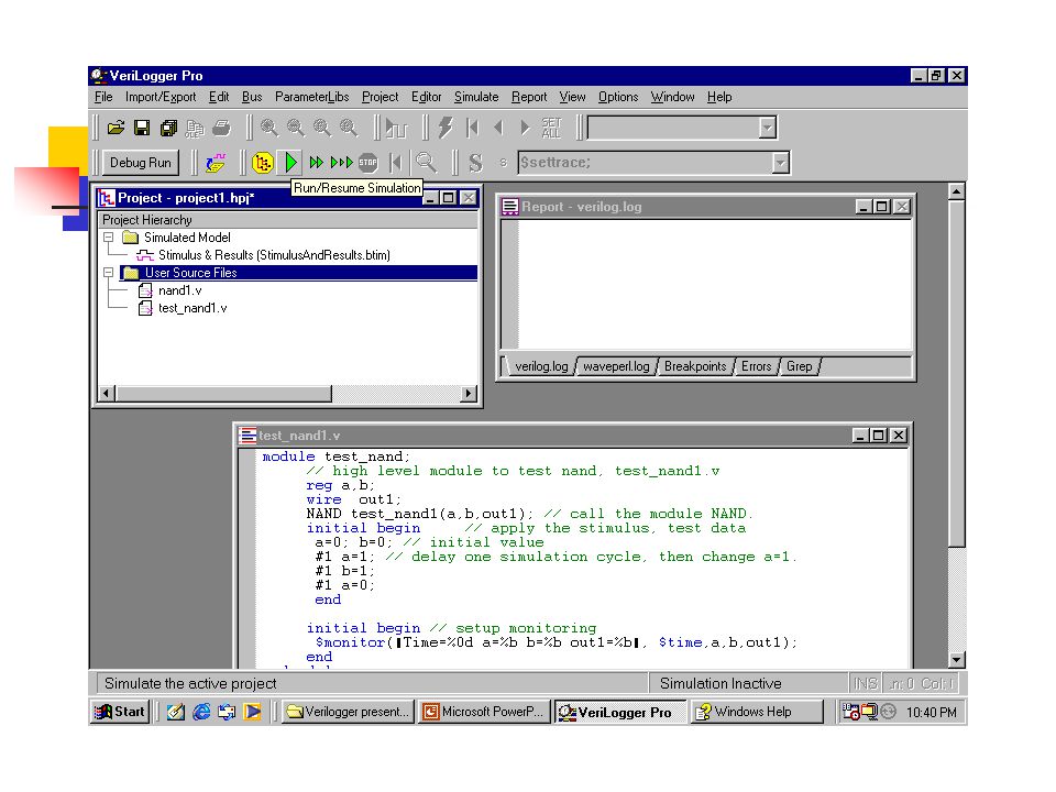
Example of gate NAND Save the HDL files as nand1.v in menu [Editor] [Save HDL File As] and save another HDL file as test_nand1.v Attach these two HDL files to a new project test.hpj in [project window] Run the simulation program run/resume simulation button or in the [simulate].
![Example of gate NAND Save the HDL files as nand1.v in menu [Editor] [Save HDL File As] and save another HDL file as test_nand1.v Attach these two HDL files to a new project test.hpj in [project window] Run the simulation program run/resume simulation button or in the [simulate].](http://images.slideplayer.com/16/5125128/slides/slide_19.jpg "Example of gate NAND Save the HDL files as nand1.v in menu [Editor] [Save HDL File As] and save another HDL file as test_nand1.v Attach these two HDL files to a new project test.hpj in [project window] Run the simulation program run/resume simulation button or in the [simulate].")
20
How to build a new project?

25
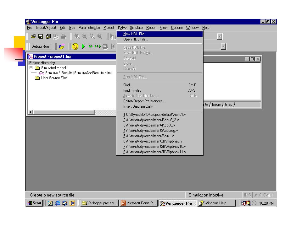
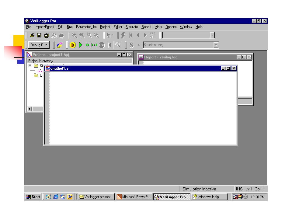
How to create a HDL file?

29
How to save the HDL file?

34
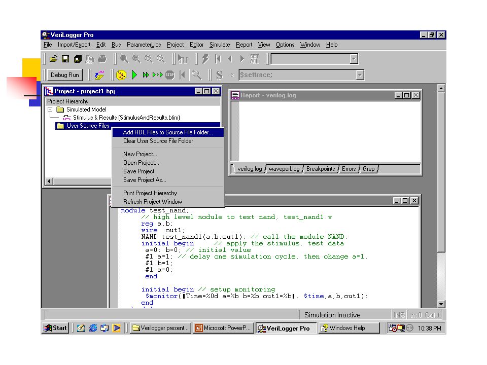
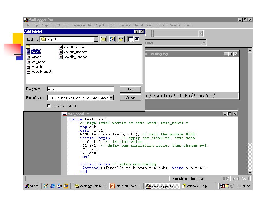
How to add a source HDL file to a Project(project1)
")
40
Now, Ready to run the program!

43
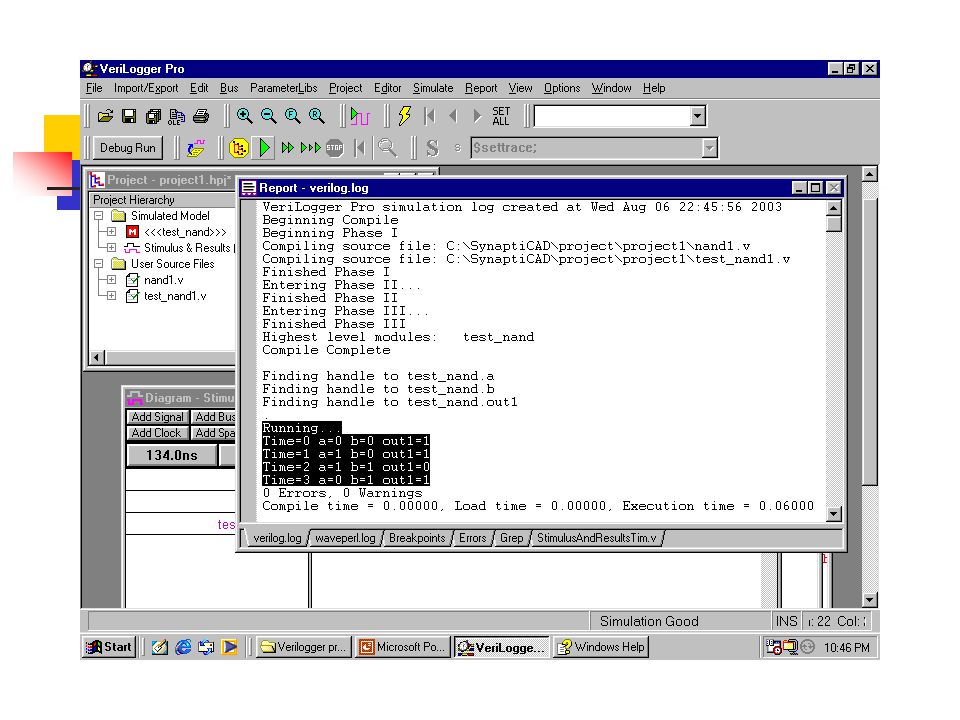
The Report Window of Verilogger.(all the simulation information is in this window)
")
45
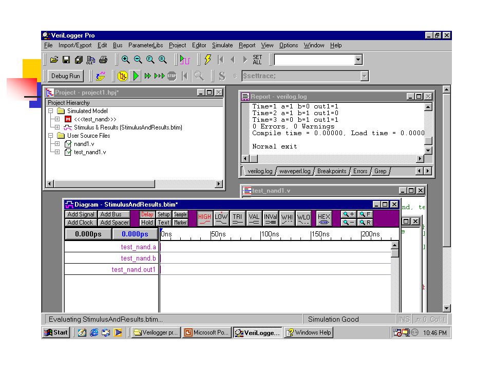
Example of gate NAND Simulation report from Verilog-Report window. Running... Time=0 a=0 b=0 out1=1 Time=1 a=1 b=0 out1=1 Time=2 a=1 b=1 out1=0 Time=3 a=0 b=1 out1=1 0 Errors, 0 Warnings Compile time = 0.00000, Load time = 0.00000, Execution time = 0.06000 Normal exit

46
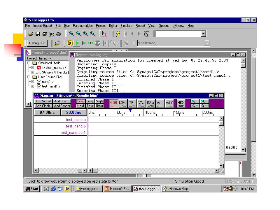
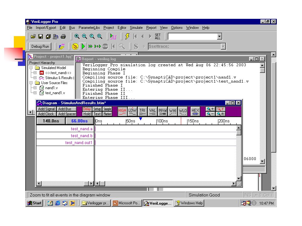
Diagram window of Simulation result

50
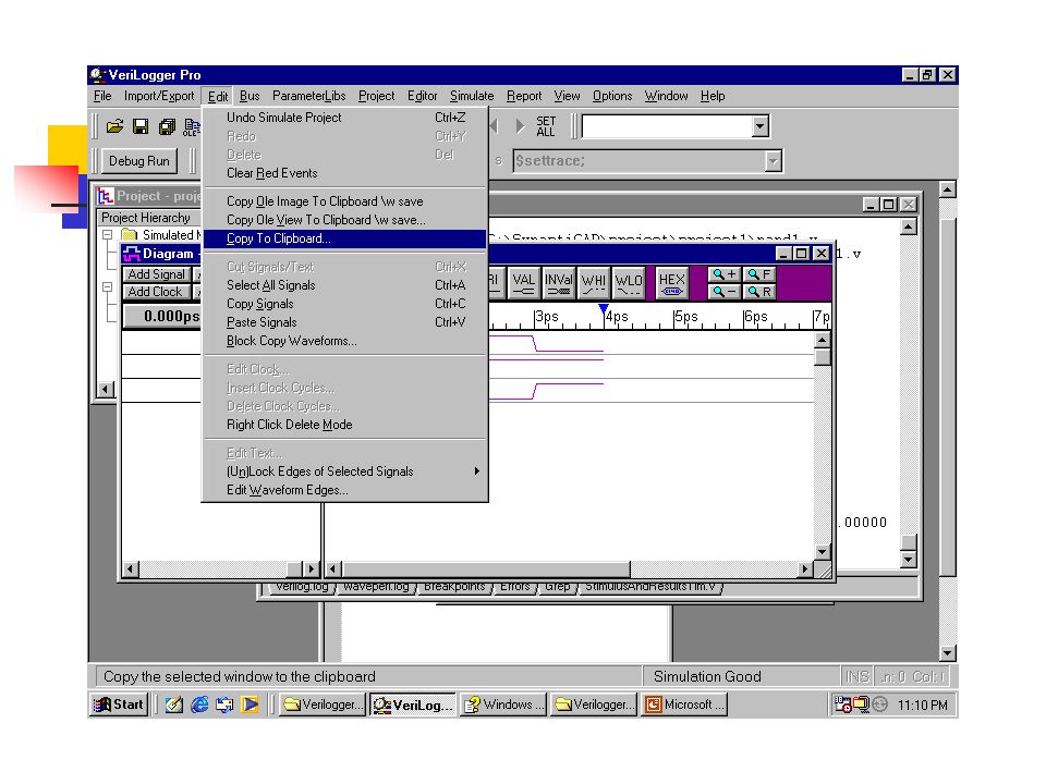
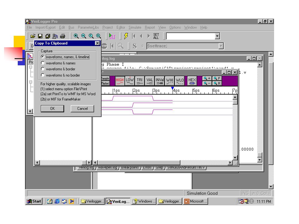
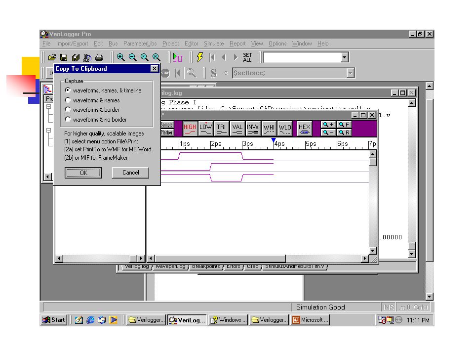
How to copy the diagram to Microsoft Word!

51
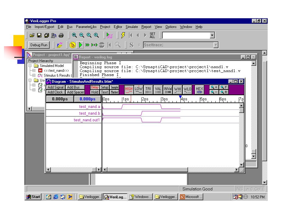
Example of gate NAND Wave from Verilog diagram. Verilog windows click the diagram windows click [edit] copy to clipboard select “ wave form, name and time line ” select “ ok ” then you can paste the diagram to anywhere you want.

55
You can paste the diagram here!

56
Examples 2 NAND Structural model //structural model of a Nand gate // program nand2.v module NAND(in1, in2, out2); input in1,in2; output out2; nand nand2(out2,in1,in2);// first port must be output. endmodule

57
Examples 2 NAND Test module same as the behavioral model. Save the HDL Editor program as nand2.v, another as test_nand2.v Attach these two HDL files to a new project test.hpj Run the simulation program run/resume simulation button or in the [simulate].

58
Examples 2 NAND Nand2 simulation report. Running... Time=0 a=0 b=0 out1=1 Time=1 a=1 b=0 out1=1 Time=2 a=1 b=1 out1=0 Time=3 a=0 b=1 out1=1 0 Errors, 0 Warnings Compile time = 0.00000, Load time = 0.11000, Execution time = 0.00000 Normal exit

59
Examples 2 NAND Wave of Nand2

60
Example 3 Run the additional program in the verilogger to understand the detail of programming. MUX2_1. OR gate NOT gate Fulladder

Similar presentations


 Set up basic environment Select Gates or Modules to Be simulated (Insert Program Code) Run Waveform.>")


>")


>")


 VHDL >")


 introduction to VHDL and Verilog entities.>")

