Download presentation
Presentation is loading. Please wait.

1
Ch. 7: Dynamics

2
Example: three link cylindrical robot
Up to this point, we have developed a systematic method to determine the forward and inverse kinematics and the Jacobian for any arbitrary serial manipulator Forward kinematics: mapping from joint variables to position and orientation of the end effector Inverse kinematics: finding joint variables that satisfy a given position and orientation of the end effector Jacobian: mapping from the joint velocities to the end effector linear and angular velocities Example: three link cylindrical robot Or any other coordinate frame on the manipulator

3
Why are we studying inertial dynamics and control?
Kinematic vs dynamic models: What we’re really doing is modeling the manipulator Kinematic models Simple control schemes Good approximation for manipulators at low velocities and accelerations when inertial coupling between links is small Not so good at higher velocities or accelerations Dynamic models More complex controllers More accurate

4
Methods to Analyze Dynamics
Two methods: Energy of the system: Euler-Lagrange method Iterative Link analysis: Euler-Newton method Each has its own ads and disads. In general, they are the same and the results are the same.

5
Terminology Definitions Generalized coordinates:
Vector norm: measure of the magnitude of a vector 2-norm: Inner product: Definitions of other norms

6
Euler-Lagrange Equations
We can derive the equations of motion for any nDOF system by using energy methods

7
Ex: 1DOF system To illustrate, we derive the equations of motion for a 1DOF system Consider a particle of mass m Using Newton’s second law: Mass is constrained to move vertically. Note that the potential energy is defined with respect to a ‘zero energy state’

8
Euler-Lagrange Equations
If we represent the variables of the system as generalized coordinates, then we can write the equations of motion for an nDOF system as:

9
Ex: 1DOF system

10
Ex: 1DOF system Let the total inertia, J, be defined by: :
Note that this result gives a nonlinear equation: we can linearize using the small angle assumption

11
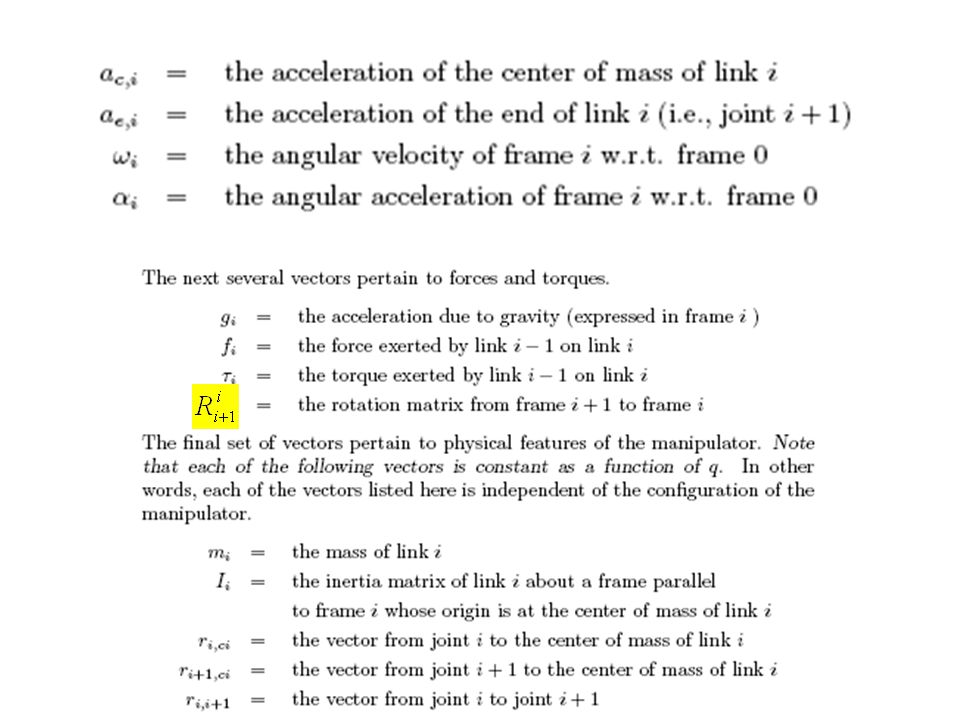
Inertia Inertia, in the body attached frame, is an intrinsic property of a rigid body In the body frame, it is a constant 3x3 matrix: The diagonal elements are called the principal moments of inertia and are a representation of the mass distribution of a body with respect to an axis of rotation: r is the distance from the axis of rotation to the particle

12
Inertia The elements are defined by: Center of gravity The point
principal moments of inertia r(x,y,z) is the density cross products of inertia The point
 is the density. cross products of inertia. The point.")
13
The Inertia Matrix Calculate the moment of inertia of a cuboid about its centroid: Since the object is symmetrical about the CG, all cross products of inertia are zero

14
Inertia First, we need to express the inertia in the body-attached frame Note that the rotation between the inertial frame and the body attached frame is just R

15
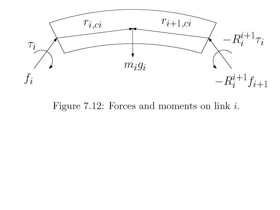
Newton-Euler Formulation
Rules: Every action has an equal reaction The rate of change of the linear momentum equals the total forces applied to the body The rate change of the angular momentum equals the total torque applied to the body.

16
Newton-Euler Formulation
Euler equation

19
Force and Torque Equilibrium
Force equilibrium Torque equilibrium

20
Angular Velocity and Acceleration

21
Initial and terminal conditions

22
L1 L2 F Next class… Moment of Inertia

23
L1 L2 F

Similar presentations


 O The angular momentum of a particle, about the reference point O, is defined as the vector product of the position, relative.>")


