Download presentation
Presentation is loading. Please wait.

1
Analysis of a Pendulum Problem after Jan Jantzen http://www.erudit.de/erudit/demos/cartball/index.htm

2
Inverted pendulum Balancing an inverted pendulum is a good demonstration problem, because it is difficult, swift, and spectacular. It is a standard problem used in many classrooms and commercial software packages. This version is not the usual pole balancer, but rather a steel ball rolling on a pair of arched tracks. The objective of the demo is to present the basic concepts of fuzzy control, in an easily accessible manner. The ball can be balanced using conventional techniques for comparison. Fuzzy control is different in the sense that the control strategy is a set of rules rather than mathematical equations.

3
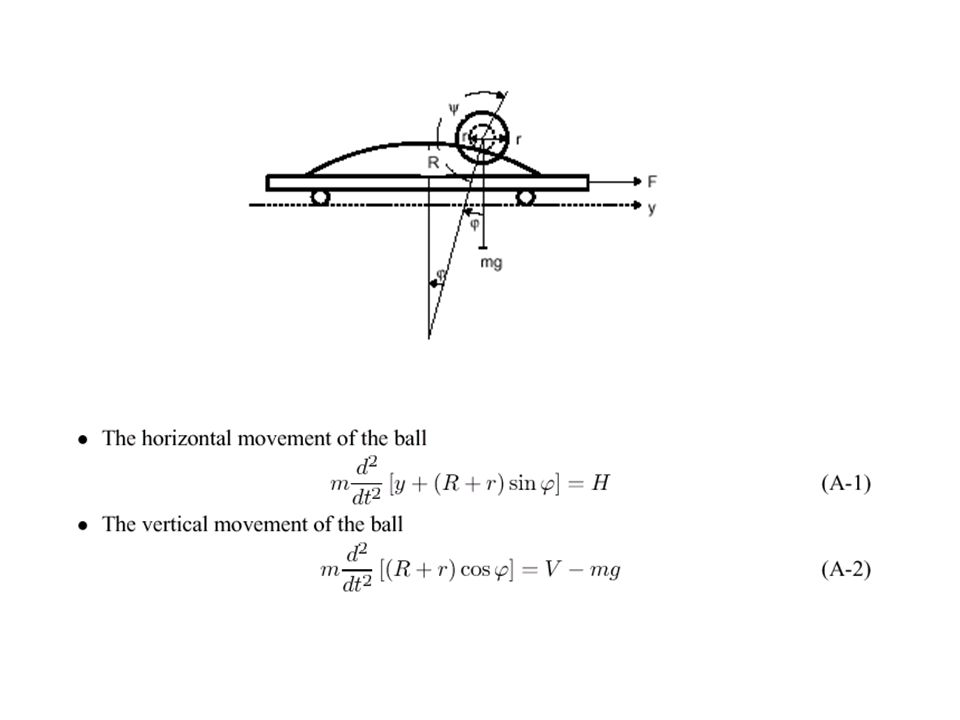
The cart moves on a pair of tracks horizontally mounted on a heavy support. The control objective is to balance the ball on the top of the arc and at the same time place the cart in a desired position. We will analyze the ball and cart separately and apply the basic physical equations related to the vertical reaction force Y and the horizontal reaction force K. Friction forces are neglected. The problem

6
They are nonlinear due to the trigonometric functions, and they are coupled such that occurs on the left side of (A-6) and on the right side of (A-7); the situation is the reverse in the case of.
 and on the right side of (A-7); the situation is the reverse in the case of.")
8
The model can be linearized around the origin. In order to avoid errors we will linearize (A-6)-(A-7) rather than the nonlinear state-space equations. Introduce the following approximations to the trigonometric functions
-(A-7) rather than the nonlinear state-space equations. Introduce the following approximations to the trigonometric functions.")
10
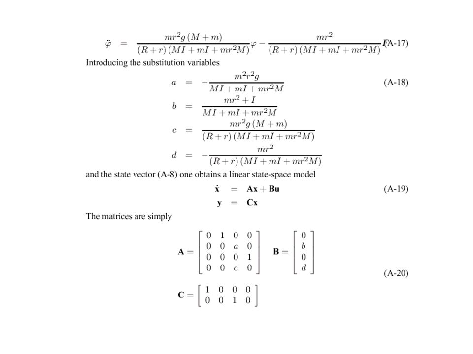
With the data in Table 1 the actual values of the constants are: a = -1.34 b = 0.301 c = 14.3 D = -0.386

11
State feedback control Notice that the control signal is now the voltage U rather than the force F, for convenience. The block diagram shows how the four states are fed back into the controller, which combines them linearly.

12
This is a state-space form as well, but of the closed-loop system. Stability is guaranteed if none of the eigenvalues of the closed-loop system matrix A+BK are in the right half of the complex plane (all k’s must be positive). Jorgensen found (in 1974) by trial and error the following values satisfactory: K= [5,5,120,8] Using optimization techniques (Linear Quadratic Regulator – Matlab Toolbox, will give a fast and stable controller with little overshoot from K= [24,24,162,44]
. Jorgensen found (in 1974) by trial and error the following values satisfactory: K= [5,5,120,8] Using optimization techniques (Linear Quadratic Regulator – Matlab Toolbox, will give a fast and stable controller with little overshoot from K= [24,24,162,44].")
13
Cascade Control It is quite intuitive to divide the system into two subsystems, one for the ball, another for the cart; –it makes it more manageable. The ball seems to require faster control reaction than the positioning of the cart, –and it is standard practice to have a fast inner loop, in this case a PD controller reacting on the ball angle makes it reach its reference, –which takes commands from a slower outer loop, in this case a PD controller reacting on the cart position

14
System Block Diagram

15
Fuzzy control of a pendulum problem Fuzzy control Fuzzy control Demo

16
The default membership functions are triangular. Examples of membership functions are MVL (moves left), SST (stands still), and MVR (moves right).
, SST (stands still), and MVR (moves right)..")
17
Graph Show Charts When enabled the following Plots show up after starting a new simulation: - cart position y and cart control signal U 1 against time - cart phase plot, g 1 *y against g 2 *dy - ball angle and ball control signal U 2 against time. - ball phase plot, g 3 * against g 4 * - ball control signal U 1, cart control signal U 2, and U 1 +U 2 against time

Similar presentations