Download presentation
Presentation is loading. Please wait.

1
LECTURE 2

2
Circuit Analysis Techniques

3
Circuit Analysis Techniques
Voltage Division Principle Current Division Principle Nodal Analysis with KCL Mesh Analysis with KVL Superposition Thévenin Equivalence Norton’s Equivalence

8
Circuit Analysis using Series/Parallel Equivalents
Begin by locating a combination of resistances that are in series or parallel. Often the place to start is farthest from the source. Redraw the circuit with the equivalent resistance for the combination found in step 1. Repeat steps 1 and 2 until the circuit is reduced as far as possible. Often (but not always) we end up with a single source and a single resistance. Solve for the currents and voltages in the final equivalent circuit.
 we end up with a single source and a single resistance. Solve for the currents and voltages in the final equivalent circuit.")
10
Working Backward

12
Voltage Division

13
Application of the Voltage-Division Principle

15
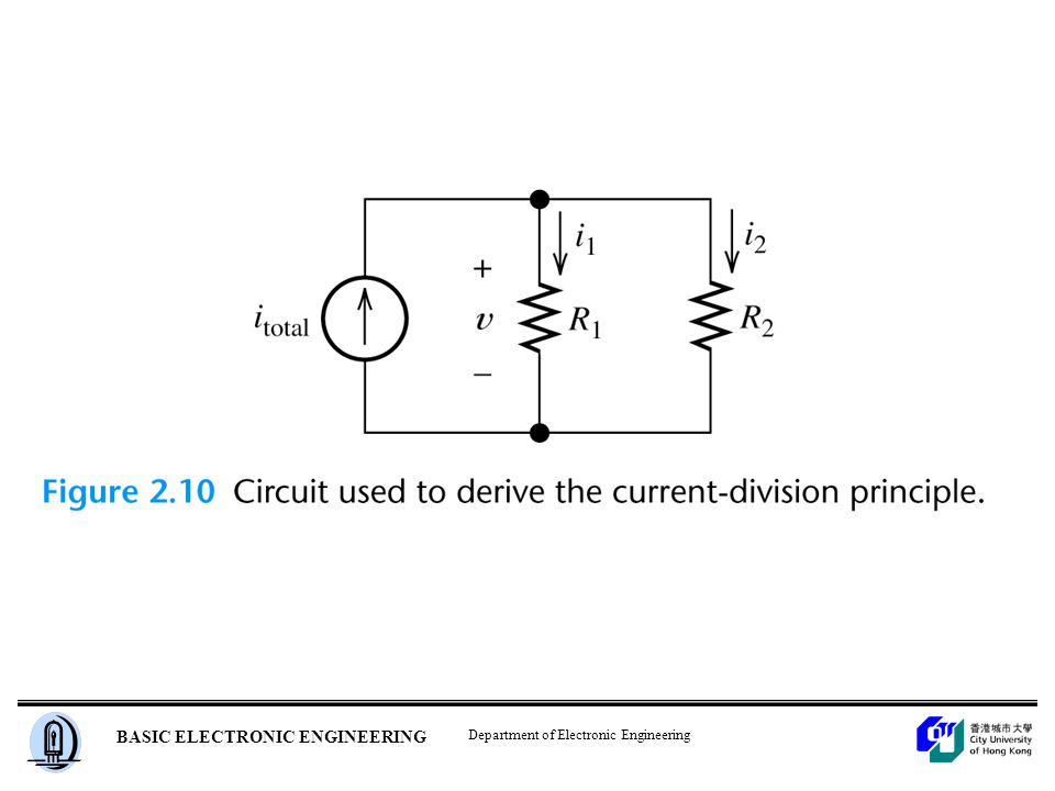
Current Division

17
Application of the Current-Division Principle

18
Voltage division and current division Voltage division

19
Current division

20
Although they are very important concepts, series/parallel equivalents and the current/voltage division principles are not sufficient to solve all circuits.

21
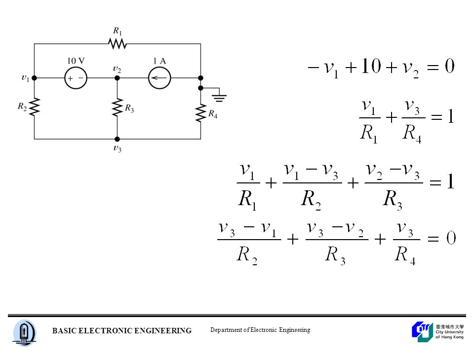
Node Voltage (Nodal) Analysis
 Analysis")
22
Definitions of node and Supernode

23
Obtain values for the unknown voltages across the elements in the circuit below.
At node 1 At node 2

25
Writing KCL Equations in Terms of the Node Voltages for Figure 2.16

26
node 1 node 2 node 3

27
No. of unknown: v1, v2, v3 No. of linear equation : 3 Setting up nodal equation with KCL at Node 1, Node 2, Node 3

28
No. of unknown: v1, v2, v3 No. of linear equation : 3 Setting up nodal equation with KCL at Node 1, Node 2, Node 3

29
Problem with node 3, it is rather hard to set the nodal equation at node 3, but still solvable. Why?
As there is no way to determine the current through the voltage source, but v3=Vs v3 Problem with node 3, it is rather hard to set the nodal equation at node 3 but still solvable. Same as before.

30
May Not Be That Simple

31
Circuits with Voltage Sources
We obtain dependent equations if we use all of the nodes in a network to write KCL equations. Any branch with a voltage source: define SUPERNODE, sum all current either in or out at the supernode with KCL use KVL to set up dependent equation involving the voltage source.

32
(a) The circuit of Example 4
(a) The circuit of Example 4.2 with a 22-V source in place of the 7-W resistor. (b) Expanded view of the region defined as a supernode; KCL requires that all currents flowing into the region must sum to zero, or we would pile up or run out of electrons. At node 1: At the “supernode:”
 The circuit of Example 4.2 with a 22-V source in place of the 7-W resistor. (b) Expanded view of the region defined as a supernode; KCL requires that all currents flowing into the region must sum to zero, or we would pile up or run out of electrons. At node 1: At the supernode:")
33
A B Summing all the current out from the supernode A For supernode A, EXCLUDE THE SOURCE Why? As the current via the 10V source is equal to the current via R4 plus the current via R3

34
B For supernode B, EXCLUDE THE SOURCE Summing all the current into the supernode B

35
-v v2 = 0

36
Any branch with a voltage source:
define supernode, sum all current either in or out at the supernode with KCL use KVL to set up dependent equation involving the voltage source.

39
Node-Voltage Analysis with a Dependent Source
First, we write KCL equations at each node, including the current of the controlled source just as if it were an ordinary current source. Next, we find an expression for the controlling variable ix in terms of the node voltages.

42
Substitution yields

44
Node-Voltage Analysis
1. Select a reference node and assign variables for the unknown node voltages. If the reference node is chosen at one end of an independent voltage source, one node voltage is known at the start, and fewer need to be computed. 2. Write network equations. First, use KCL to write current equations for nodes and supernodes. Write as many current equations as you can without using all of the nodes. Then if you do not have enough equations because of voltage sources connected between nodes, use KVL to write additional equations. 3. If the circuit contains dependent sources, find expressions for the controlling variables in terms of the node voltages. Substitute into the network equations, and obtain equations having only the node voltages as unknowns. 4. Put the equations into standard form and solve for the node voltages. 5. Use the values found for the node voltages to calculate any other currents or voltages of interest.

45
Step 1.Reference node Step 1. v1 Step 2. Step 1 v2

46
Step 1 Step 1 v2 v1 Step 2 v3 Step 1 ref supernode Step 3 node 1

47
Mesh Current Analysis

48
Definition of a loop Definition of a mesh

49
Choosing the Mesh Currents
When several mesh currents flow through one element, we consider the current in that element to be the algebraic sum of the mesh currents.

51
Writing Equations to Solve for Mesh Currents
If a network contains only resistors and independent voltage sources, we can write the required equations by following each current around its mesh and applying KVL.

52
For mesh 1, we have For mesh 2, we obtain For mesh 3, we have

53
Determine the two mesh currents, i1 and i2, in the circuit below.
For the left-hand mesh, i ( i1 - i2 ) = 0 For the right-hand mesh, 3 ( i2 - i1 ) i = 0 Solving, we find that i1 = 6 A and i2 = 4 A. (The current flowing downward through the 3-W resistor is therefore i1 - i2 = 2 A. )
 = 0. For the right-hand mesh, 3 ( i2 - i1 ) + 4 i = 0. Solving, we find that i1 = 6 A and i2 = 4 A. (The current flowing downward through the 3-W resistor is therefore i1 - i2 = 2 A. )")
54
Mesh Currents in Circuits Containing Current Sources
*A common mistake is to assume the voltages across current sources are zero. Therefore, loop equation cannot be set up at mesh one due to the voltage across the current source is unknown Anyway, the problem is still solvable.

55
It is the supermesh. Mesh 3:
As the current source common to two mesh, combine meshes 1 and 2 into a supermesh. In other words, we write a KVL equation around the periphery of meshes 1 and 2 combined. It is the supermesh. Mesh 3: Three linear equations and three unknown

56
Find the three mesh currents in the circuit below.
Creating a “supermesh” from meshes 1 and 3: ( i1 - i2 ) ( i3 - i2 ) i3 = 0 [1] Around mesh 2: 1 ( i2 - i1 ) i ( i2 - i3 ) = 0 [2] Finally, we relate the currents in meshes 1 and 3: i1 - i3 = [3] Rearranging, i i i3 = 7 [1] -i i i3 = 0 [2] i i3 = 7 [3] Solving, i1 = 9 A, i2 = 2.5 A, and i3 = 2 A.
 + 3 ( i3 - i2 ) + 1 i3 = 0 [1] Around mesh 2: 1 ( i2 - i1 ) + 2 i2 + 3 ( i2 - i3 ) = 0 [2] Finally, we relate the currents in meshes 1 and 3: i1 - i3 = 7 [3] Rearranging, i1 - 4 i2 + 4 i3 = 7 [1] -i1 + 6 i2 - 3 i3 = 0 [2] i1 - i3 = 7 [3] Solving, i1 = 9 A, i2 = 2.5 A, and i3 = 2 A.")
57
supermesh of mesh1 and mesh2
branch current current source

58
Three equations and three unknown.

59
Mesh-Current Analysis
1. If necessary, redraw the network without crossing conductors or elements. Then define the mesh currents flowing around each of the open areas defined by the network. For consistency, we usually select a clockwise direction for each of the mesh currents, but this is not a requirement. 2. Write network equations, stopping after the number of equations is equal to the number of mesh currents. First, use KVL to write voltage equations for meshes that do not contain current sources. Next, if any current sources are present, write expressions for their currents in terms of the mesh currents. Finally, if a current source is common to two meshes, write a KVL equation for the supermesh. 3. If the circuit contains dependent sources, find expressions for the controlling variables in terms of the mesh currents. Substitute into the network equations, and obtain equations having only the mesh currents as unknowns. 4. Put the equations into standard form. Solve for the mesh currents by use of determinants or other means. 5. Use the values found for the mesh currents to calculate any other currents or voltages of interest.

60
Superposition Superposition Theorem – the response of a circuit to more than one source can be determined by analyzing the circuit’s response to each source (alone) and then combining the results Insert Figure 7.2
 and then combining the results. Insert Figure 7.2.")
61
Superposition Insert Figure 7.3

62
Superposition Analyze Separately, then Combine Results

63
Use superposition to find the current ix.
Current source is zero – open circuit as I = 0 and solve iXv Voltage source is zero – short circuit as V= 0 and solve iXv

64
Use superposition to find the current ix.
The controlled voltage source is included in all cases as it is controlled by the current ix.

65
Voltage and Current Sources
Insert Figure 7.7

66
Voltage and Current Sources
Insert Figure 7.8

67
Voltage and Current Sources
Insert Figure 7.9

68
Source Transformation
Under what condition, the voltage and current of the load is the same when operating at the two practical sources? For voltage source For current source , We have,

70
Voltage and Current Sources
Equivalent Voltage and Current Sources – for every voltage source, there exists an equivalent current source, and vice versa

72
Thevenin’s Theorem Thevenin’s Theorem – any resistive circuit or network, no matter how complex, can be represented as a voltage source in series with a source resistance

73
Thevenin’s Theorem Thevenin Voltage (VTH) – the voltage present at the output terminals of the circuit when the load is removed Insert Figure 7.18

74
Thevenin’s Theorem Thevenin Resistance (RTH) – the resistance measured across the output terminals with the load removed
 – the resistance measured across the output terminals with the load removed.")
75
Thévenin Equivalent Circuits

78
Thévenin Equivalent Circuits

79
Thévenin Equivalent Circuits

80
Finding the Thévenin Resistance Directly
When zeroing a voltage source, it becomes a short circuit. When zeroing a current source, it becomes an open circuit. We can find the Thévenin resistance by zeroing the sources in the original network and then computing the resistance between the terminals.

83
Computation of Thévenin resistance

84
Equivalence of open-circuit and Thévenin voltage

85
A circuit and its Thévenin equivalent

86
Superposition As the voltage source does not contribute any output voltage, Only the current source has the effect.

87
Determine the Thévenin and Norton Equivalents of Network A in (a).
Source transformation

88
Find the Thévenin equivalent of the circuit shown in (a).
As i = -1, therefore, the controlled voltage source is -1.5V. Use nodal analysis at node v, Thus, Rth =v/I = 0.6/1 = 0.6 ohms

90
Applications of Thevenin’s Theorem
Load Voltage Ranges – Thevenin’s theorem is most commonly used to predict the change in load voltage that will result from a change in load resistance

91
Applications of Thevenin’s Theorem
Maximum Power Transfer Maximum power transfer from a circuit to a variable load occurs when the load resistance equals the source resistance For a series-parallel circuit, maximum power occurs when RL = RTH

92
Applications of Thevenin’s Theorem
Multiload Circuits Insert Figure 7.30

93
Norton’s Theorem Norton’s Theorem – any resistive circuit or network, no matter how complex, can be represented as a current source in parallel with a source resistance

94
Norton’s Theorem Norton Current (IN) – the current through the shorted load terminals Insert Figure 7.35

95
Computation of Norton current

96
Norton’s Theorem Norton Resistance (RN) – the resistance measured across the open load terminals (measured and calculated exactly like RTH)
 – the resistance measured across the open load terminals (measured and calculated exactly like RTH)")
97
Norton’s Theorem Norton-to-Thevenin and Thevenin-to-Norton Conversions
Insert Figure 7.39

98
Step-by-step Thévenin/Norton-Equivalent-Circuit Analysis
1. Perform two of these: a. Determine the open-circuit voltage Vt = voc. b. Determine the short-circuit current In = isc. c. Zero the sources and find the Thévenin resistance Rt looking back into the terminals.

99
2. Use the equation Vt = Rt In to compute the remaining value.
3. The Thévenin equivalent consists of a voltage source Vt in series with Rt . 4. The Norton equivalent consists of a current source In in parallel with Rt .

101
Maximum Power Transfer
The load resistance that absorbs the maximum power from a two-terminal circuit is equal to the Thévenin resistance.

102
Graphical representation of maximum power transfer
Power transfer between source and load

Similar presentations


>")
 method of circuit analysis Superposition method of circuit analysis Equivalent circuit.>")


