Download presentation
Presentation is loading. Please wait.

1
Operations and Availability GG3

2
Key decisions Summary of Key Decisions for the Baseline Design The linac will have two parallel tunnels so that the support equipment may be accessed without entering the accelerator enclosure. There will be a keep-alive positron source that can provide positrons when the electron DR or linac is down. Each region of the ILC will have sufficient beam stoppers and shielding so people can be in that region while beam is in another region. A large effort will be needed to make individual components reliable and/or redundant.

3
Availability Methodology simulation Mean Time Between Failure (MTBF) Mean Time To Repair (MTTR) the performance of the accelerator is degraded in a component specific manner. o headroom goes to zero o zero luminosity o completely break the ILC. Each component has one of 3 repair methods Hot repairable No access needed Access required The goal set was to have the calculated downtime be only 15%.

4
Specifications needed to achieve adequate availability how the required calculated availability of 85% was achieved. There is a 3% energy overhead in each main linac that can be switched on without delay. The roughly 5 GeV accelerators have a 5% energy overhead and the smaller linacs have a 5% overhead plus an extra cavity. There are hot spare klystrons/modulators with waveguide switches in all low energy linac regions. Without the hot spare switchable klystrons, the availability dropped 1.3%. When klystrons are not in the accelerator tunnel, they can be hot swapped. This will require some type of valve in the output waveguide. Most electronics modules not in the accelerator tunnel can be hot swapped.

5
Specifications needed to achieve adequate availability -cont- There are tune up dumps and shielding between each region of accelerator so that one region can be run while people are in another region. Problems with the overall site power will cause 0.5% downtime. …If each dip causes 12 hours of downtime, these correspond to 0.27% (single feed) and 0.02% (dual feed). The total downtime due to any cryo plant being down is 1%. If there are 6 cryo plants then each must be up 99.85% including outages due to their incoming utilities. This is 3-6 times better than the Fermilab and LEP cryo plants. The starting MTBF used for magnet power supplies of 200,000 hours is 4 times better than SLAC/Fermilab experience. This probably requires redundant regulators.
 and 0.02% (dual feed). The total downtime due to any cryo plant being down is 1%. If there are 6 cryo plants then each must be up 99.85% including outages due to their incoming utilities. This is 3-6 times better than the Fermilab and LEP cryo plants. The starting MTBF used for magnet power supplies of 200,000 hours is 4 times better than SLAC/Fermilab experience. This probably requires redundant regulators..")
6
Specifications needed to achieve adequate availability -cont- The power coupler interlock electronics and sensors have MTBFs of 1 million hours due to redundancy. Cavity tuner motors are a potential reliability concern. Its seriousness is unclear at this time. In the simulation they have a starting MTBF of 1 million hours, 2 times better than SLAC warm experience and much better than TTF cold experience. There is a spare e+ target beam-line with 8 hour switch-over. Failed superconducting linac quads can be tuned around in 2 hours. There will be no vacuum leaks that force a cryomodule to be warmed up for a repair before the run can continue. Vacuum leaks that can be ameliorated with the installation of a turbo-pump are allowed. Interlock systems are a particular concern. Even if they don’t actually break, giving many false trips can effectively inhibit stable operation.

7
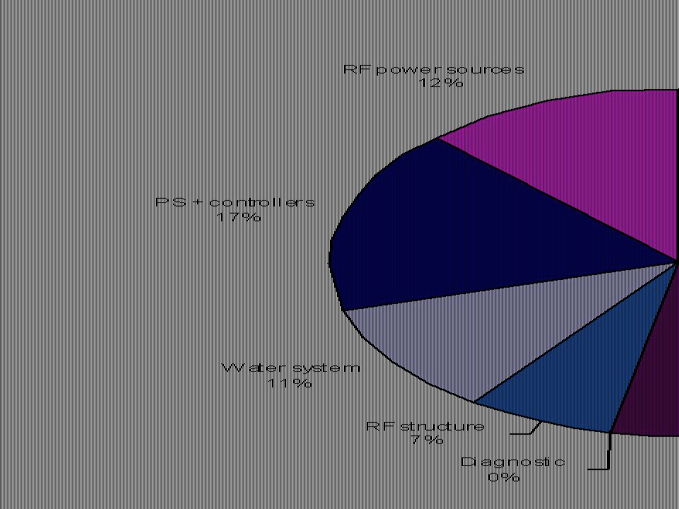
MTBFs used to obtain the desired 15% downtime

8
This shows how the total downtime of 17% is distributed among the various regions of the ILC. The simulation had 2 tunnels with an undulator e+ source with a strong keep-alive source and the “A” MTBF improvement factors shown in column 2 of

10
Need for positron keep-alive source The reason is that the electron arm has to be up and fully tuned before positrons can be produced. This loss in operational efficiency can be largely mitigated by introducing a standby keep-alive positron source based on conventional technology. The intensity of this keep-alive source must be sufficiently good so that BPMs can be used for all their normal purposes including beam based alignment and steering. A full intensity source with every second bunch filled could clearly fulfill the task and would be suitable to study essentially all intensity induced effects in the accelerator (e-clouds in DR etc.). A 20% intensity source will also serve the keep-alive function in many respects. A single bunch, 1% intensity at 5Hz repetition is likely too low to fulfill the requirement.
. A 20% intensity source will also serve the keep-alive function in many respects. A single bunch, 1% intensity at 5Hz repetition is likely too low to fulfill the requirement..")
11
Need for 2 tunnels Note the significant decrease in integrated luminosity when going from 2 tunnels to 1.

12
Extra features needed for Commissioning Phased commissioning For the commissioning of the ILC the largest amount of time is expected to be spent in the damping rings. More generally, careful thought should be given to the construction schedule to allow as much commissioning time as possible while downstream construction proceeds. Electron source and reversible e+ DR Low emittance electron beams will be necessary to explore and understand the limitations of the positron damping rings. The damping ring polarity should hence be reversible and a low emittance electron source made available for injection into the positron damping ring. Globally synchronized data acquisition for fault analysis Bypass line to skip e- DR for early e- linac commissioning It would be nice to be able to inject directly into the main linac for commissioning before the DR is complete or when it is broken.

13
Automated surveying system Alignment questions will recur during commissioning. It will be very helpful to have an automated surveying system implemented that allows for alignment of accelerator components. Machine Protection System (MPS) The Machine Protection System was discussed jointly between the operations and availability global group and the diagnostics and controls global group. Its description is in the controls section, not this one. Operability Not much work has been done on operability issues other than the availability simulations. The possible need for extra diagnostics (or better resolution) to track down where an obscure problem occurs. Needed control system features. Existence of enough control points and diagnostics to properly tune the beam Specification of feedbacks and automated tuning procedures
 The Machine Protection System was discussed jointly between the operations and availability global group and the diagnostics and controls global group. Its description is in the controls section, not this one. Operability Not much work has been done on operability issues other than the availability simulations. The possible need for extra diagnostics (or better resolution) to track down where an obscure problem occurs. Needed control system features. Existence of enough control points and diagnostics to properly tune the beam Specification of feedbacks and automated tuning procedures.")
14
What do we have to do Reliability Continue benchmarking Push other groups to design in reliability Provide advice to other groups on how to configure for reliability, perhaps by running availsim with various configurations (e.g. 1 or 16 channel controllers), DRs in same or different tunnel, some electronics in the accelerator tunnel? Establish official unavailability budget on discussion with other groups. At what level should this be done? Commissioning How do layout issues (DR location) effect commissioning Phasing of construction and commissioning Where do we need temporary dumps and shielding for commissioning during construction
, DRs in same or different tunnel, some electronics in the accelerator tunnel. Establish official unavailability budget on discussion with other groups. At what level should this be done. Commissioning How do layout issues (DR location) effect commissioning Phasing of construction and commissioning Where do we need temporary dumps and shielding for commissioning during construction.")
15
MPS and fault recovery Concentrate on major/expensive pieces such as dumps How much beam simulation is needed? PPS What are the PPS regions (places where people can be when there is beam in other PPS regions) How much shielding is needed What are the PPS zones (areas divided by gates that can be independently searched) Number and location of dumps Tuning What diagnostics are needed including resolutions? What devices are needed to do the tuning? Transportation, people and supply depots
 How much shielding is needed What are the PPS zones (areas divided by gates that can be independently searched) Number and location of dumps Tuning What diagnostics are needed including resolutions. What devices are needed to do the tuning. Transportation, people and supply depots.")
Similar presentations


 < 250 GeV purpose: not to generate a new ILC estimate, but to facilitate SB2009 decisions Peter H. Garbincius,>")

 *Work supported by the EU, FP7 MAX contract number.>")


