Download presentation
Presentation is loading. Please wait.

1
Ignition System Fundamentals
Chapter 37

2
Objectives Describe the functions of ignition system parts
Explain the operation of points, electronic, and computer ignition systems Give an overview of the different spark advance methods Describe distributorless and conventional ignition distributor variations and operation Draw a wiring diagram showing the primary and secondary ignition systems

3
Introduction Ignition system Turns the engine on and off
Creates a timed spark and distributes it to the cylinders Spark is distributed to the spark plugs Jumps the gap and ignites air-fuel mixture Timing of the spark varies with engine speed Amount of time for fuel to burn in the cylinder is constant

4
Basic Ignition System Modern vehicles have computer-controlled ignition systems Main ignition system categories Distributor ignition (DI) Electronic ignition (EI) (i.e., distributorless, direct ignition, or coil over plug) All ignition types use battery, switch, coil, switching device, and spark plugs Circuits Primary circuit: low-voltage (battery) Secondary circuit: high-voltage (spark)
 Electronic ignition (EI) (i.e., distributorless, direct ignition, or coil over plug) All ignition types use battery, switch, coil, switching device, and spark plugs. Circuits. Primary circuit: low-voltage (battery) Secondary circuit: high-voltage (spark)")
5
Primary Circuit Primary ignition system components
Battery and charging system Ignition switch and coil primary windings Switching device Distributor cam lobes or crank/cam sensor Ground return path Battery voltage converted to high voltage by ignition coil Spark jumps across gap at end of spark plug Spark timing is critical to power output

6
Ignition Switch Multiposition switch
Powers the ignition circuit on and off Operates the steering wheel lock and a buzzer or light

7
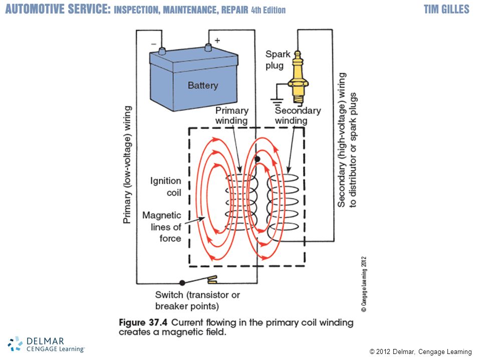
Ignition Coil Heart of the ignition system Magnetic field
Has a low-voltage primary winding and high-voltage secondary winding Magnetic field Collapses when current flow is interrupted in primary winding Magnetic lines of force Cut across the secondary windings and create high voltage and low amperage

10
Ignition Coil (cont'd.) Saturation Dwell
Coil is saturated when magnetic field finished its buildup inside coil Coil saturation time depends on amount of current in primary winding Dwell Length of time current flows in primary winding Determined by ignition control module Electronic ignition varies dwell time

11
Secondary Ignition Parts
Secondary circuit Delivers high voltage from coil to spark plugs Distributor ignition (DI) system components Cam Distributor cap and rotor DI systems: electricity flows from coil to distributor cap and rotor Distributor rotates at one-half crankshaft speed Spark plug cables are inserted in the distributor cap following engine firing order
 system components. Cam. Distributor cap and rotor. DI systems: electricity flows from coil to distributor cap and rotor. Distributor rotates at one-half crankshaft speed. Spark plug cables are inserted in the distributor cap following engine firing order.")
12
Spark Plugs Spark ignites compressed air-fuel mixture
Length of threaded area called reach Heat range indicates how fast heat travels away from the center electrode Determined by how far ceramic insulator extends into combustion chamber Spark plugs have a tapered seat or flat seat with a gasket to seal against cylinder head There is controversy over long-life spark plugs Precious metals are used to prolong life

13
Spark Plugs (cont'd.) Resistor plugs and wires Spark plug cable
Resistance added to secondary ignition system with spark plugs or spark plug cables Resistor inside spark plug raises firing voltage required by the output coil Spark plug cable Resistor cables are very fragile Secondary wiring must be well insulated Leak in insulation will cause a spark to short to ground

14
Electronic Ignitions Trigger mechanism Nonelectric ignition systems
Controls current flow in primary coil winding Nonelectric ignition systems Used mechanical contact points Alternately energized and then opened primary ignition circuit Contact points require periodic replacement Experience wear to rubbing block that rides against the distributor cam

15
Electronic Ignition Operation
Transistor triggers buildup and collapse of magnetic field Housed in an ignition module or in PCM Transistor Electronic switch or relay Power transistor: controlled by driver transistor Components: emitter, collector, and base Switches when a small amount of current is applied to its base

17
Electronic Ignition Variations
Common electronic trigger: permanent magnet (PM) AC generator pickup Works like an alternator Pickup coil: wrapped around iron pole piece Trigger wheel: attached to distributor shaft Low magnetic reluctance Reluctor tooth moves away from pole piece and magnetic field becomes weaker Ignition module: alternating signal from PM generator is converted to DC
 AC generator pickup. Works like an alternator. Pickup coil: wrapped around iron pole piece. Trigger wheel: attached to distributor shaft. Low magnetic reluctance. Reluctor tooth moves away from pole piece and magnetic field becomes weaker. Ignition module: alternating signal from PM generator is converted to DC.")
18
Hall-Effect Pickups Most popular electronic ignition triggering device
Has a stationary sensor and rotating trigger wheel Signal is a rise in voltage followed by a drop Components: permanent magnet, Hall element, and cupped metal ring Creates a small analog voltage signal strengthened by an amplifier Converted to square wave by Schmidt trigger Generate rpm signals and are very accurate Used as a crankshaft position sensor

19
Magnetoresistive Sensors
Create a square wave digital signal Includes two MR pickups phased a small distance from each other Creates its own five-volt reference signal Permanent magnet is sandwiched between two sideways magnetic reluctance pickups One pickup gets the signal sooner than the other Differential signal switches a Schmidt trigger

20
Optical Sensors A beam of light controls primary circuit
Sensor shines beam on one side of slotted disc Disc interrupts the light: voltage stops Automotive engine use Called crank angle sensors Computer determines crankshaft position, cylinder identification, and rpm from openings

21
Ignition Modules Newer ignition modules functions
Turn primary current on and off Limit current Vary dwell Current limiting system Has variable resistance within an ignition module Ignition module turns current flow off as soon as coil primary winding is saturated

22
Ignition Timing Ignition is timed Ignition timing variation
So it occurs just before piston reaches top of compression stroke Ignition timing variation Computer determines best ignition timing setting Advanced or retarded in response to engine speed and load changes, altitude, and engine temperature Intake manifold vacuum senses engine load

23
Ignition Timing (cont'd.)
Computer systems continuously adjust spark timing to optimize power and emissions Some functions were not possible with mechanical distributors Throttle position sensor determines throttle position MAP sensor determines intake manifold pressure Primary trigger interprets engine speed Coolant temperature sensor allows adjustments for changes in engine temperature

24
Detonation Sensor Controls maximum spark advance
Piezoelectric crystal detects the frequency of spark knock PCM retards timing in steps until vibration stops Advances timing until knocking occurs Checks if outside air temperature is high to prevent detonation

25
Distributorless Ignition
Advantages of EI Reduced cost and lower maintenance No rotor, distributor cap, or spark plug cables Crankshaft position sensor Determines engine speed and crankshaft position Camshaft position sensor Gives information for sequencing fuel injection system and coil firing

26
Distributorless Ignition (cont’d.)
Waste spark One coil for every two spark plugs Some engines have two spark plugs per cylinder One on the combustion chamber’s intake side The other is on the exhaust side

Similar presentations


 Produces high.>")


>")


 IGNITION SYSTEM DISTRIBUTORLESS IGNITION SYSTEM.>")
