Download presentation
Presentation is loading. Please wait.

1
Edexcel A2 Physics Unit 4 : Chapter 2.3 : Electromagnetic Effect
Prepared By: Shakil Raiman

2
2.3.1 Magnetic Pole and Field
Magnetic Pole: The two ends of a magnet where the magnetic field lines converge are called magnetic poles. Magnetic Field: The three-dimensional region of space in which a magnet has influence or a magnetic pole feel a force is called magnetic field.

3
2.3.2 Magnetic Field (Pictures)
")
4
2.3.3 Maxwell’s Equations: An electric field can exert a force on a charged particle. A magnetic field can exert a force on a charged particle if it is moving.

5
2.3.4 Magnetic field lines or Magnetic Flux
Magnetic field lines are the lines which show the direction in which a lone north pole will be pushed. The amount of magnetic field within a loop or coil is called magnetic flux. It is denoted by . SI unit is weber (Wb). Like all field patters, the closer the lines are together, the stronger the field is.
. Like all field patters, the closer the lines are together, the stronger the field is.")
6
2.3.5 Magnetic Flux density and Tesla
Magnetic flux density is a measure of the strength of a magnetic field.Magnetic flux density is defined as magnetic flux acting normally per unit area. It is denoted by B. Tesla (T) is the SI unit for magnetic flux density.
 is the SI unit for magnetic flux density.")
7
2.3.6 Relation of Magnetic Flux and Flux density.
=BsinA Problem:

8
2.3.7: Fleming’s Left Hand Rule
Magnetic fields can affect moving charges as well as magnetic poles. If a wire is placed in a magnetic field and pass a current through it, the wire will feel a force on it. This is called the motor effect.

9
2.3.7: Fleming’s Left Hand Rule
The direction of this force can be found by Fleming’s Left Hand Rule. Fleming’s Left Hand Rule: If the thumb, first finger and second finger are placed at right angles to each other, the first finger represents the direction of the magnetic field, the second finger the direction of the current and the thumb represents the direction of motion ( direction of the force)
")
10
2.3.8: The Strength of Electromagnetic Force on a current carrying conductor
The strength of the force, F, on a wire which has a current, I, through it whilst it is in a magnetic field, B, is given by the equation: 𝐹=𝐵𝐼𝑙𝑠𝑖𝑛𝜃 If = 90, 𝐹=𝐵𝐼𝑙 (to remember Fred = Bil)
")
11
2.3.8: The Strength of Electromagnetic Foece
A consequence of the expression F=BIl on a motor can be made more powerful, or faster, by: Increasing the current through the motor (I) Increasing the number of turns of wire in the motor (l) Increasing the magnetic field within the motor (B) The magnetic field strength is usually maximised by making the central rotating core out of soft iron. Some motors use electromagnets to provide the field, and these could be strengthened by increasing the current through them.
 Increasing the number of turns of wire in the motor (l) Increasing the magnetic field within the motor (B) The magnetic field strength is usually maximised by making the central rotating core out of soft iron. Some motors use electromagnets to provide the field, and these could be strengthened by increasing the current through them.")
12
2.3.9: The Strength of Electromagnetic Foece on a charged particle
The motor effect happens too for a moving charge in a magnetic field. The strength of the force on a charged particle moving across a magnetic field is given by the equation: 𝐹=𝐵𝑞𝑣𝑠𝑖𝑛𝜃 If =90, 𝐹=𝐵𝑞𝑣 For electron q=e, so 𝐹=𝐵𝑒𝑣 (Fred = Bev)
")
13
2.3.10: Problems:1

14
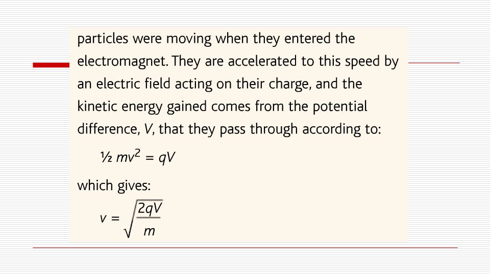
2.3.11: The mass spectrometer:

15
2.3.11: The mass spectrometer:

20
2.3.11: The mass spectrometer:

21
2.3.12: Problems:

22
2.3.12: Problems:

23
2.3.12: Problems:

24
2.3.13: Electromagnetic Induction
If we move a magnet near a wire the electrons in the wire will feel a force tending to make them move through the wire. This is an emf – if the wire is in a complete circuit, then the electrons will move, forming an electric current. This is one principle by which we generate electricity. Reversing the direction of magnetic field or the direction of the relative motion will reverse the direction of the force on the electrons, reversing the polarity of the emf.

25
2.3.14: Flux Linkage The induced emf may well be tiny and only detectable by the most sensitive voltmeter. The amount of magnetic flux interacting with a coil of wire is known as the magnetic flux linkage, and is simply the product of the number of turns of wire and the flux in that region: flux linkage = N measured in weber-turns But =BA So, flux linkage = BAN

26
2.3.15: Faraday’s Law & Lenz’s Law & Calculating emf.
Faraday’s Law: The magnitude of an induces emf is proportional to the rate of change of flux linkage. Lenz’s Law: The direction of an induced emf is such as to oppose the change creating it. Putting Faraday’s and Lenz’s laws together gives us an expression for calculating an induced emf:

27
2.3.16: Fleming’s Right Hand Rule
The direction of an induced emf can be found using Fleming’s right hand rule. This is known as dynamo rule. If the thumb, first finger and second finger are placed at right angles to each other, the first finger represents the direction of the magnetic field, the thumb represents the direction of motion ( direction of the force) and the second finger the direction of the current
 and the second finger the direction of the current.")
28
2.3.17: Electromagnetic Induction Using an Electromagnet
We have a pair of coils linked together by a soft iron core. Iron is extremely good at carrying magnetism, and in the setup shown, virtually all the magnetic field generated by the primary coil on the left would interact with the right.

29
2.3.17: Electromagnetic Induction Using an Electromagnet
When the primary switch is first closed, the primary coil suddenly produces a magnetic field which was not previously there. This means that a magnetic field is now within the secondary coil, which had not previously been there. This sudden change of flux linkage will generate an emf in the secondary coil. Once the electromagnetic field is stable there will no longer be any change in the flux linkage over time, and so there will be no further induced emf in the secondary. The voltmeter needle would kick and then return to zero. If the primary circuit is switched off, the magnetic field it produces would suddenly disappear and a brief emf would be induced in the opposite direction to the switch-on voltage. The voltmeter needle would kick in the opposite direction and then return to zero again. The circuit and situation described here is not really of much practical use, although it can be responsible for current surges in circuitry which can cause damage. The same principle is more usefully applied in the transformer.

30
2.3.18: Transformers In a transformer, an alternating current is supplied to the primary. As this current is constantly varying, the electromagnetic field produced by the primary coil is constantly varying. This means that there will be a constantly varying induced emf in the secondary. This emf will bary at the same rate as the a.c. Supplied to the primary.

31
2.3.18: Transformer It will also change constantly, depending on the varying rate of change of flux linkage. This comes from the strength of the magnetic field (which in turn depends on the number of turns on the primary coil) and the number of turns on the secondary coil. So, the ratio of voltages between primary and secondary is identical to the ratio of the number of turns on these coils: This is how the transformer can change voltage. More turns on the secondary gives step-up transformer, in which the output voltage is higher than the input voltage. More turns on the primary gives a step-down transformer, in which the output voltage is lower than the input voltage.
 and the number of turns on the secondary coil. So, the ratio of voltages between primary and secondary is identical to the ratio of the number of turns on these coils: This is how the transformer can change voltage. More turns on the secondary gives step-up transformer, in which the output voltage is higher than the input voltage. More turns on the primary gives a step-down transformer, in which the output voltage is lower than the input voltage.")
32
Thank You All Wish you all very good luck.

Similar presentations


 about the interaction between magnetic fields>")
deduce from Faraday’s experiments on electromagnetic induction or other appropriate experiments: (i) that a changing magnetic field.>")


 14-2: Field Intensity (H) 14-3: B-H Magnetization Curve.>")


