Download presentation
Presentation is loading. Please wait.

1
Oscilloscope

2
1.Electron guns 2.Electron beams 3.Focusing coils 4.Deflection coils 5.Anode connection 6.Mask for separating beams for red, green, and blue part of displayed image 7.Phosphor layer with red, green, and blue zones 8.Close-up of the phosphor- coated inner side of the screen

3
Oscilloscope Referred to as cathode-ray oscilloscope, it is a universal instrument that displays wave forms on a phosphor coated "screen" of a cathode- ray tube (CRT). The oscilloscope represents a two dimensional graph of signals VS time or in general, other signals (instead of time).
..")
4
oscilloscope The general purpose of an oscilloscope is displaying voltage signals and other electrical signals or non-electrical signals. There non-electrical signals would have to be converted to voltage signals (using transducers). NOTE: many of the oscilloscope controls can be adjusted to suit the individual performance required by the operator.
. NOTE: many of the oscilloscope controls can be adjusted to suit the individual performance required by the operator..")
5
oscilloscope When using an oscilloscope: 1. You can determine the time and voltage value of given signal. 2.You can calculate the signal frequencies. 3.You can tell malfunction in the oscilloscope is the component is destroying the signal. 4.You can find out how much of the signal is DC or AC. 5.You can tell if there is some noise with the signal

6
Oscilloscope NOTE: oscilloscopes come in many shapes and sizes, hence, beside the power supply, the basic oscilloscope has different subsystems.

7
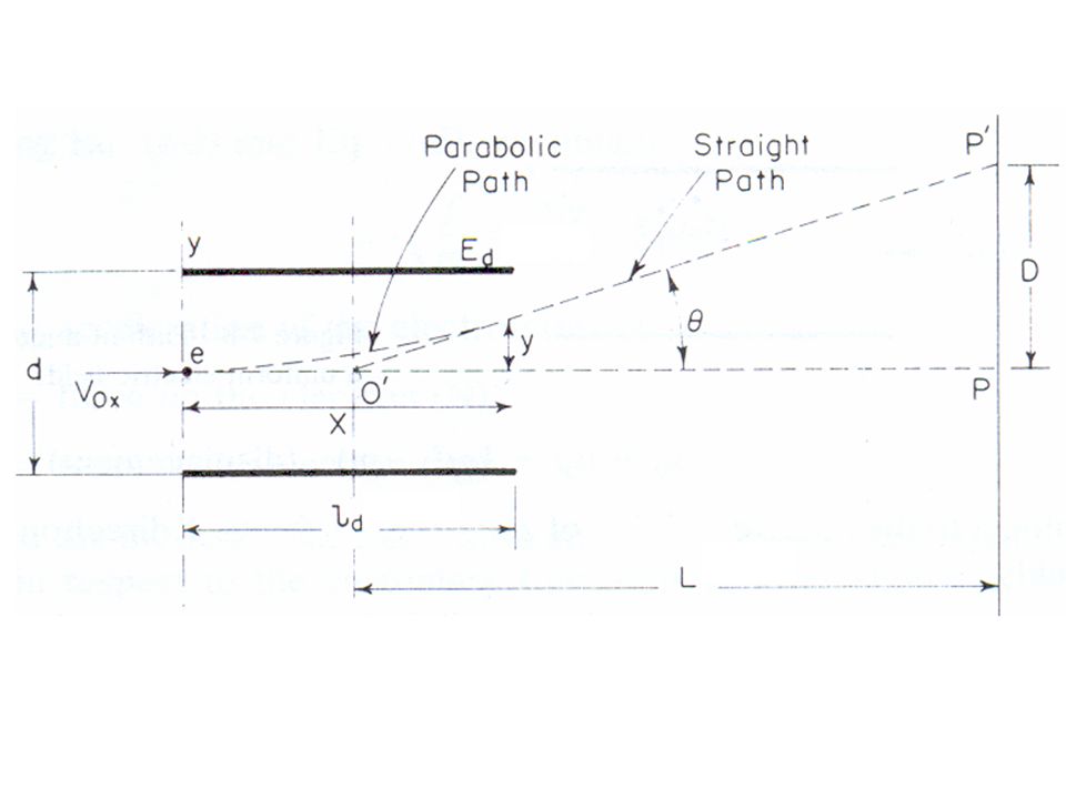
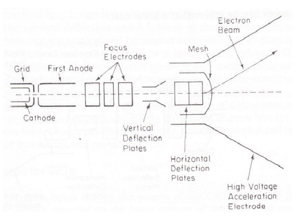
Now, on the screen a spot of light is formed where the electron beam strikes and leaves a glowing trail as the beam moves across the screen (fades unless traced over) The beam passes first between one pair of vertical and then horizontal deflection plates when the voltage is applied to the vertical deflection plates this produces an electrical field between them, which deflect the electron beam either up or down similarly the electrical field in the Horizontal plates deflects the beam left or right.
 The beam passes first between one pair of vertical and then horizontal deflection plates when the voltage is applied to the vertical deflection plates this produces an electrical field between them, which deflect the electron beam either up or down similarly the electrical field in the Horizontal plates deflects the beam left or right.")
9
CRT operation: The signal displayed on the screen passes through the calibrated attenuator. The attenuator matches the high impedance of the scope to the low impedance of the vertical pre-amplifier; it also scales the input signal to a level that the vertical pre-amps can handle. Then the signal is magnified by the vertical amplifier, which provides the required deflection voltage.

10
The trigger circuit: 1.Trigger level: selects the voltage of which the input signal initiates a sweep. 2.Slope: determines whether a sweep begins on the positive or negative ongoing slope of the wave form.

11
The horizontal deflection plates provide a similar action where its input maybe switched between two plates of inputs: 1.External input (x-y) 2.internal input: (time-base0generator) or (sweep generator)The circuit initiating the sweep is called the trigger circuit.
 2.internal input: (time-base0generator) or (sweep generator)The circuit initiating the sweep is called the trigger circuit.")
13
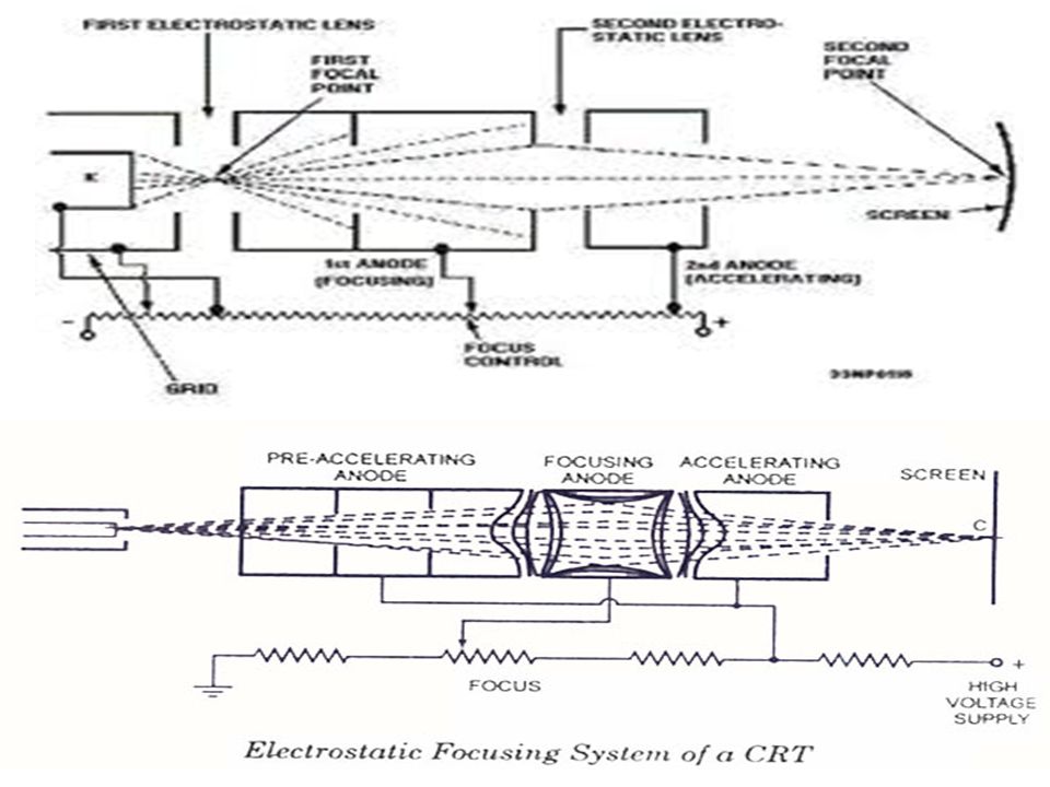
The heater cathode emits electrons. They are accelerated to the first accelerating anode when the amount of the cathode current controls the intensity of the spot. The beam is focused and then sent to be given some additional energy by the 2nd accelerating anode. Focusing the beam prevents the electrons from being diverged and producing an ill-defined spot on the phosphoric screen. The electron beam is focused with an electrostatic lens. This lens requires three elements with the center elements at a lower potential that the two outer elements.

18
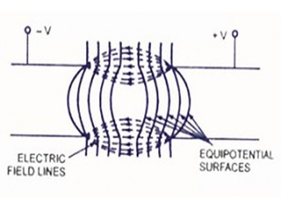
NOTE: 1.The force on the electron is in the direction normal to the equal-potential surface. 2.Only electrons passing through the exact centre will experience no force. 3.Electrons that displayed away from the center would experience a force and thus would be focused (deflected) with other electrons.
 with other electrons..")
28
For the (S) and (G), note that the highly accelerated beam possesses more kinetic energy and thus produces a brighter image on the screen. The light on the screen depends on the amount of energy that is transferred into the screen by the beam.

29
Post deflection acceleration: If the velocity of the electron beam slows down then the light on the screen will drop off. Therefore great acceleration of the beam is desired in fast oscilloscopes. However, fast acceleration makes it more difficult to deflect the beam. To overcome this problem we have two ways:

30
1) Use of scan expansion mesh: Accelerating the electron beam to a relatively low velocity (through a few 1000s volts) then, after the deflection, the beam is farther accelerated to the desired final velocity (through 10 kV or more) this is performed by a metallic mesh which acts as a magnifying lens that causes the deflection to be further increased.
 Use of scan expansion mesh: Accelerating the electron beam to a relatively low velocity (through a few 1000s volts) then, after the deflection, the beam is farther accelerated to the desired final velocity (through 10 kV or more) this is performed by a metallic mesh which acts as a magnifying lens that causes the deflection to be further increased.")
32
NOTE: the second acceleration doesn’t affect the deflection sensitivity The disadvantages: 1.The mesh tends to defocus the electron beam (due to conducting some of the electrons away from the screen), which reduces the beam current and thus reduces the spot intensity on the screen. 2.The electron beam tends to be defocused in the area of the deflection plates, this is caused by the repulsion from charge distributions within the beam.

33
2 ) Meshless scan expansion : In this method the focus electrodes are constructed from individual metal wafers which allow for different focusing characteristics.
 Meshless scan expansion : In this method the focus electrodes are constructed from individual metal wafers which allow for different focusing characteristics.")
35
Now the beam is accelerated to final velocity by aquadrapole lens which to do it without distorting or defocusing the beam, now this causes an increase in the deflection sensitivity (here the typical values are 2.3 v/cm (vertical deflection), 3.7 v/cm ( horizontal deflection) where the difference between horizontal and vertical is due to the occurrence of (VD) at low velocity.
, 3.7 v/cm ( horizontal deflection) where the difference between horizontal and vertical is due to the occurrence of (VD) at low velocity.")
36
The mesh-less electron gun can be used for oscilloscopes that operate at frequencies higher than 100 MHz, using integrated circuits with (40 –50)V for deflection Note: The mesh-less tube makes smaller and lighter oscilloscope.
V for deflection Note: The mesh-less tube makes smaller and lighter oscilloscope.")
37
Oscilloscope screens: For the inner surface of the screen, It is phosphoric which has the property of emitting light when stimulated by radiation (kinetic energy), this property is referred to as fluorescence.
, this property is referred to as fluorescence.")
38
The screen (phosphor) can continue the emission of light after cutting off the source; this property is known as phosphor sense. The time of continuing emission of light is referred to as persistence of phosphor. The persistence of phosphor is measured in terms of the time required for the image to decay to ascertain percentage (10%) of the original light output.
 of the original light output..")
39
The intensity of the image on the screen is known as “luminance”, which depends on: 1.The number of electrons strikes the screen/second. 2.energy with the electrons, which depends on the accelerated voltage. 3.The physical characteristics of the phosphor screen. (in general,phosphor (p31)) is known to be the best for general purpose viewing since it has high luminance and medium persistence.
) is known to be the best for general purpose viewing since it has high luminance and medium persistence..")
41
Notes: Excessive current density may cause a permanent damage to the phosphor through burning. The process (controlling the current density) depends on two factors: 1.Beam density which controlled by : a)Intensity b)Focus c)Astigmatism 2. Duration of excitation: which controlled by the sweep (time/div).
 depends on two factors: 1.Beam density which controlled by : a)Intensity b)Focus c)Astigmatism 2. Duration of excitation: which controlled by the sweep (time/div)..")
42
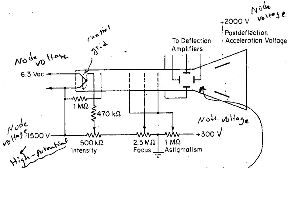
Note: the striking electrons release secondary emission electrons. These electrons having low velocity are called by conductive coating known as aquadag on the inside of the glass tube. The CRT must be supplied with several dc potentials to provide proper acceleration controls and focusing. The 1 st requirement is a law voltage for the cathode heater. The 2 nd requirement is the total accelerating voltage which is applied in two halves:- 1.High negative potential applied to the cathode grid. 2.High positive potential applied to the post deflection acceleration electrode. This process prevents the output of the deflection amplifier from being at high potential and simplifies the design of the circuit.

43
The required operating voltage are derived from voltage dividers with the following controllers :- 1.Intensity: - this controller varies the potential between the cathode and the control grid, and simply adjusts the beam current. For the intensity control an increase in the beam current increase the # of electrons striking the phosphoric screen and adjusts the light output. 2. Focus: - this controller adjusts the focal length of the electron lens 3. Astigmatism: - this controller adjusts the potential between the deflection plates and the 1 st accelerating electrode used to produce a focused spot.

44
Note: since the deflection sensitivity depends on the value of the accelerating voltage this voltage is usually regulated.

Similar presentations


, make.>")


 basics: –Many measurement are made easier by the CRO because it will display not only amplitude,>")


>")


