Download presentation
Presentation is loading. Please wait.

1
Chapter 31 Faraday’s Law 31.1 Faraday’s Law of Induction
Motional emf

2
31.1 Faraday’s Law of Induction
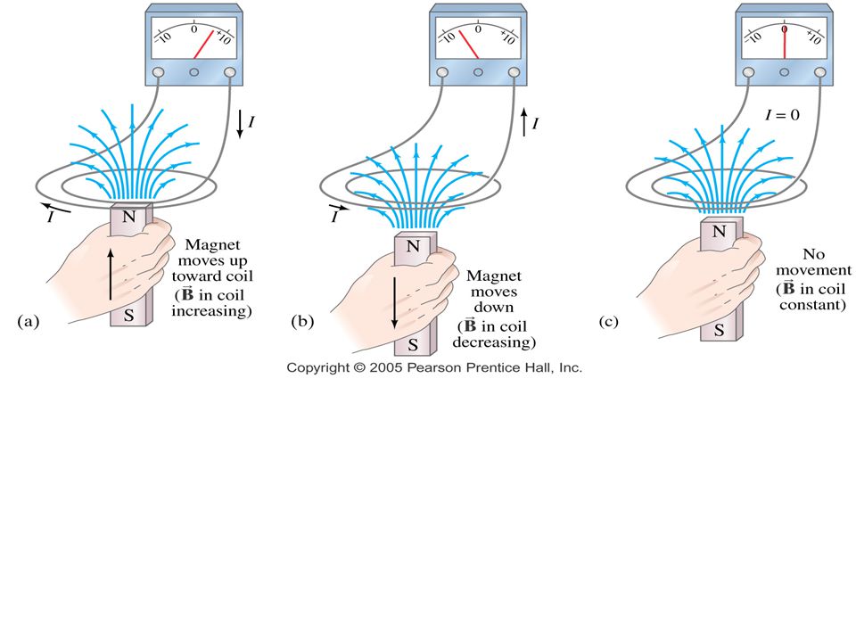
Figure 31.1 (a) When a magnet is moved toward a loop of wire connected to a sensitive ammeter, the ammeter deflects as shown, indicating that a current is induced in the loop. (b) When the magnet is held stationary, there is no induced current in the loop, even when the magnet is inside the loop. (c) When the magnet is moved away from the loop, the ammeter deflects in the opposite direction, indicating that the induced current is opposite that shown in part (a). Changing the direction of the magnet’s motion changes the direction of the current induced by that motion. Active Figure 31.1 (a) When a magnet is moved toward a loop of wire connected to a sensitive ammeter, the ammeter deflects as shown, indicating that a current is induced in the loop. (b) When the magnet is held stationary, there is no induced current in the loop, even when the magnet is inside the loop. (c) When the magnet is moved away from the loop, the ammeter deflects in the opposite direction, indicating that the induced current is opposite that shown in part (a). Changing the direction of the magnet’s motion changes the direction of the current induced by that motion.
 When a magnet is moved toward a loop of wire connected to a sensitive ammeter, the ammeter deflects as shown, indicating that a current is induced in the loop. (b) When the magnet is held stationary, there is no induced current in the loop, even when the magnet is inside the loop. (c) When the magnet is moved away from the loop, the ammeter deflects in the opposite direction, indicating that the induced current is opposite that shown in part (a). Changing the direction of the magnet’s motion changes the direction of the current induced by that motion. Active Figure 31.1 (a) When a magnet is moved toward a loop of wire connected to a sensitive ammeter, the ammeter deflects as shown, indicating that a current is induced in the loop. (b) When the magnet is held stationary, there is no induced current in the loop, even when the magnet is inside the loop. (c) When the magnet is moved away from the loop, the ammeter deflects in the opposite direction, indicating that the induced current is opposite that shown in part (a). Changing the direction of the magnet’s motion changes the direction of the current induced by that motion.")
4
Lenz’s Law The magnetic is moving away from the coil so the magnetic field is decreasing, thus the current is in a direction to off-set the decrease. The magnetic is moving toward the coil so the magnetic field is increasing, thus the current is in a direction to off-set the increase.

5
If the magnet is held stationary and the coil is moved toward or away from the magnet, the galvanometer needle will also deflect. From these observations, you can conclude that a current is set up in the circuit as long as there is relative motion between the magnet and the coil. This current is set up in the circuit even though there are no batteries in the circuit. The current is said to be an induced current, which is produced by an induced EMF.

6
Faraday’s Experiment A coil is connected to a switch and a battery.
This is called the primary coil and the circuit is called the primary circuit. The coil is wrapped around an iron ring to intensify the magnetic field produced by the current through the coil. A second coil, on the right, is wrapped around the iron ring and is connected to a galvanometer. This is secondary coil and the circuit is the secondary circuit. There is no battery in the secondary circuit and the secondary circuit is not connected to the primary coil.

7
The only purpose of this circuit is to detect any current that might be produced by a change in the magnetic field. When the switch in the primary circuit is closed, the galvanometer in the secondary circuit deflects in one direction and then returns to zero. When the switch is opened, the galvanometer deflects in the opposite direction and again returns to zero. The galvanometer reads zero when there is a steady current in the primary circuit. Faraday concluded that an electric current can be produced by a changing magnetic field. A current cannot be produced by a steady magnetic field. The current that is produced in the secondary circuit occurs for only an instant while the magnetic field through the secondary coil is changing. In effect, the secondary circuit behaves as though there were a source of EMF connected to it for a short instant. An induced EMF is produced in the secondary circuit by the changing magnetic field.

8
In both experiments, an EMF is induced in a circuit when the magnetic flux through the circuit changes with time. Faraday’s Law of Induction: The EMF induced in a circuit is directly proportional to the time rate of change of magnetic flux through the circuit. Magnetic flux ΦB : where ΦB is the magnetic flux threading the circuit. The negative sign is a consequence of Lenz’s law (the induced EMF opposes the change in the magnetic flux in the circuit). If the circuit is a coil consisting of N loops all of the same area and if the flux threads all loops, the induced EMF is where N is the number of turns in the loops, A is the area of one loop,εis the induced emf, and B┴ is the perpendicular component of the magnetic field.
. If the circuit is a coil consisting of N loops all of the same area and if the flux threads all loops, the induced EMF is. where N is the number of turns in the loops, A is the area of one loop,εis the induced emf, and B┴ is the perpendicular component of the magnetic field.")
9
Suppose the magnetic field is uniform over a loop of area A lying in a plane as shown in the figure below. The flux through the loop is equal to B·A·cos ; and the induced EMF is: To induce an emf we can change, the magnitude of B the area enclosed by the loop the angle between B and the normal to the area any combination of the above over time.

10
Example 31.1 One Way to Induce an emf in a Coil
A coil consists of 200 turns of wire. Each turn is a square of side 18 cm, and a uniform magnetic field directed perpendicular to the plane of the coil is turned on. If the field changes linearly from 0 to 0.50 T in 0.80 s, what is the magnitude of the induced emf in the coil while the field is changing?

12
In which direction is the current induced in the coil for each situation shown?
(counterclockwise) (no current)
 (no current)")
13
(counterclockwise) (clockwise)
 (clockwise)")
14
Rotating the coil about the vertical diameter by pulling the left side toward the reader and pushing the right side away from the reader in a magnetic field that points from right to left in the plane of the page. (counterclockwise)
")
15
Motional emf A motional emf is the emf induced in a conductor moving through a constant magnetic field The electrons in the conductor experience a force, that is directed along ℓ Under the influence of the force, the electrons move to the lower end of the conductor and accumulate there As a result of the charge separation, an electric field is produced inside the conductor The charges accumulate at both ends of the conductor until they are in equilibrium with regard to the electric and magnetic forces 4/15/2017

16
31.2 Motional emf or For equilibrium,
The electric field is related to the potential difference across the ends of the conductor: A potential difference is maintained between the ends of the conductor as long as the conductor continues to move through the uniform magnetic field If the direction of the motion is reversed, the polarity of the potential difference is also reversed 4/15/2017

17
Sliding Conducting Bar
A bar moving through a uniform field and the equivalent circuit diagram Assume the bar has zero resistance The stationary part of the circuit has a resistance R The induced emf is Since the resistance in the circuit is R, the current is 4/15/2017

18
Sliding Conducting Bar, Energy Considerations
The applied force does work on the conducting bar This moves the charges through a magnetic field and establishes a current The change in energy of the system during some time interval must be equal to the transfer of energy into the system by work The power input is equal to the rate at which energy is delivered to the resistor If the bar is moved with constant velocity, 4/15/2017

19
example Bout v Current CW Current CW, Current CCW, No current,
Week 09, Day 1 A rectangular wire loop is pulled thru a uniform B field penetrating its top half, as shown. The induced current : v Bout Current CW Current CW, Current CCW, No current, . No current The motion does not change the magnetic flux, so Faraday’s Law says there is no induced EMF, or current, or force, or torque. Of course, if we were pulling at all up or down there would be a force to oppose that motion. Class 20

20
example Clockwise Counterclockwise Neither, the current is zero
Week 9, Day 2 A circuit in the form of a rectangular piece of wire is pulled away from a long wire carrying current I in the direction shown in the sketch. The induced current in the rectangular circuit is Clockwise Counterclockwise Neither, the current is zero 1. Induced current is clockwise B due to I is into page; the flux through the circuit due to that field decreases as the circuit moves away. So the induced current is clockwise (to make a B into the page) Class 22 20
 Class")
21
example The induced current comes from Ohm’s Law.
A circular flat coil has 200 turns of wire with a total resistance of 25 W and an enclosed area of 100 cm2. There is a perpendicular magnetic field of 0.50 T that is turned off in 200 ms. Find the current induced in the coil. The magnetic flux is F = BA= (0.50 T)(100 cm2) = (0.50 T)(0.010 m2)= T m2 The change in flux is negative since it is turned off. The induced emf is E = -N DF/Dt = -(200)( Tm2) / (0.20 s) E = DV = 5.0 V The induced current comes from Ohm’s Law. I = V/R = (5.0 V) / (25 W) = 0.20 A
(100 cm2) = (0.50 T)(0.010 m2)= T m2. The change in flux is negative since it is turned off. The induced emf is E = -N DF/Dt = -(200)( Tm2) / (0.20 s) E = DV = 5.0 V. The induced current comes from Ohm’s Law. I = V/R = (5.0 V) / (25 W) = 0.20 A.")
22
Example Consider the circuit .the length of the moving rod is 0.2 m, its speed is 0.1m/s , the magnetic field-strength is 1T), and the resistance of the circuit is 0.02Ω) 1.What is the emf generated around the circuit? 2.What current flows around the circuit?
, and the resistance of the circuit is 0.02Ω) 1.What is the emf generated around the circuit 2.What current flows around the circuit")
23
3.What is the magnitude and direction of the force acting on the moving rod due to the fact that a current is flowing along it? 4.What is the power delivered by the applied force?

24
Homework 1- A circular wire loop with a radius of 20 cm. is in a constant magnetic field of 0.5 T . What is the flux through the loop if the normal to the loop makes an angle of 300 with the magnetic field? 300 normal 2-The magnetic field increases from 0.5 T to 2.5 T in 0.8 seconds. What is the average emf, e(t) induced in the loop.
 induced in the loop.")
25
3-. A 50-turn rectangular coil of dimensions 5. 00 cm × 10
3- A 50-turn rectangular coil of dimensions 5.00 cm × 10.0 cm is allowed to fall from a position where B = 0 to a new position where B = T and is the magnetic field directed perpendicular to the plane of the coil. Calculate the magnitude of the average emf that is induced in the coil if the displacement occurs in s. 4- A 25-turn circular coil of wire has diameter 1.00 m. It is placed with its axis along the direction of the Earth’s magnetic field of 50.0 μT, and then in s it is flipped 180°. An average emf of what magnitude is generated in the coil? 5- A magnetic field of T exists within a solenoid of 500 turns and a diameter of 10.0 cm. How rapidly (that is, within what period of time) must the field be reduced to zero, if the average induced emf within the coil during this time interval is to be 10.0 kV?
 must the field be reduced to zero, if the average induced emf within the coil during this time interval is to be 10.0 kV")
26
6. A 30-turn circular coil of radius 4. 00 cm and resistance 1
6. A 30-turn circular coil of radius 4.00 cm and resistance 1.00 Ω is placed in a magnetic field directed perpendicular to the plane of the coil. The magnitude of the magnetic field varies in time according to the expression B = 0.010 0t 0t2, where t is in seconds and B is in tesla. Calculate the induced emf in the coil at t = 5.00 s. 7. An automobile has a vertical radio antenna 1.20 m long. The automobile travels at 65.0 km/h on a horizontal road where the Earth’s magnetic field is 50.0 μT directed toward the north and downward at an angle of 65.0° below the horizontal. (a) Specify the direction that the automobile should move in order to generate the maximum motional emf in the antenna, with the top of the antenna positive relative to the bottom. (b) Calculate the magnitude of this induced emf. 8. A conducting rod of length ℓ moves on two horizontal, frictionless rails, as shown in Figure P If a constant force of 1.00 N moves the bar at 2.00 m/s through a magnetic field B that is directed into the page, (a) what is the current through the 8.00-Ω resistor R? (b) What is the rate at which energy is delivered to the resistor? (c) What is the mechanical power delivered by the force Fapp?
 Specify the direction that the automobile should move in order to generate the maximum motional emf in the antenna, with the top of the antenna positive relative to the bottom. (b) Calculate the magnitude of this induced emf. 8. A conducting rod of length ℓ moves on two horizontal, frictionless rails, as shown in Figure P If a constant force of 1.00 N moves the bar at 2.00 m/s through a magnetic field B that is directed into the page, (a) what is the current through the 8.00-Ω resistor R (b) What is the rate at which energy is delivered to the resistor (c) What is the mechanical power delivered by the force Fapp")
27
9-The magnetic field increases from 0. 5 T to 2. 5 T in 0. 8 seconds
9-The magnetic field increases from 0.5 T to 2.5 T in 0.8 seconds. What is the average emf, e(t) induced in the loop. 10- Blood contains charged ions. A blood vessel is 2.0 mm in diameter, the magnetic field is T, and the blood meter registers a voltage of 0.10 mV. What is the flow velocity of the blood? 11- A metal rod is forced to move with constant velocity along two parallel metal rails, connected with a strip of metal at one end, as shown in the figure. A magnetic field B = T points out of the page. (a) If the rails are separated by 25.0 cm and the speed of the rod is 55.0 cm/s, what emf is generated? (b) If the rod has a resistance of 18.0 W and the rails and connector have negligible resistance, what is the current in the rod? (c) At what rate is energy being transferred to thermal energy?
 induced in the loop. 10- Blood contains charged ions. A blood vessel is 2.0 mm in diameter, the magnetic field is T, and the blood meter registers a voltage of 0.10 mV. What is the flow velocity of the blood 11- A metal rod is forced to move with constant velocity along two parallel metal rails, connected with a strip of metal at one end, as shown in the figure. A magnetic field B = T points out of the page. (a) If the rails are separated by 25.0 cm and the speed of the rod is 55.0 cm/s, what emf is generated (b) If the rod has a resistance of 18.0 W and the rails and connector have negligible resistance, what is the current in the rod (c) At what rate is energy being transferred to thermal energy")
28
12- A solenoid (similar to one used
for a class demonstration) has a diameter of 10 cm, a length of 10 cm, and contains 3500 windings with a total resistance of 60 Ohm. The solenoid is connected in a simple loop, modeled above. Initially, the solenoid is embedded in a magnetic field of T, parallel to the axis of the solenoid, as shown. This external field is reduced to zero in 0.10 sec. During this 0.1 sec, what is the EMF in the coil, what is the current in the circuit, and what is the direction and magnitude of the magnetic field in the solenoid generated by this current? Norah Ali Al- moneef
 has a diameter of 10 cm, a length of 10 cm, and contains 3500 windings with a total resistance of 60 Ohm. The solenoid is connected in a simple loop, modeled above. Initially, the solenoid is embedded in a magnetic field of T, parallel to the axis of the solenoid, as shown. This external field is reduced to zero in 0.10 sec. During this 0.1 sec, what is the EMF in the coil, what is the current in the circuit, and what is the direction and magnitude of the magnetic field in the solenoid generated by this current Norah Ali Al- moneef.")
Similar presentations


![Lecture 20 Discussion. [1] A rectangular coil of 150 loops forms a closed circuit with a resistance of 5 and measures 0.2 m wide by 0.1 m deep, as shown.](/15/4645554/big_thumb.jpg "Lecture 20 Discussion. [1] A rectangular coil of 150 loops forms a closed circuit with a resistance of 5 and measures 0.2 m wide by 0.1 m deep, as shown.>")


 No Direction ConcepTest #17: A uniform magnetic field B points into the.>")


 Lenz’s Law (direction of induced.>")
 How to find the force, F on the electric charge, Q excreted by the field E and/or B? (2) How fields E and/or B can be created? Gauss’s.>")


