Download presentation
Presentation is loading. Please wait.

1
Cargo Pod Design Kyle Bergen Ejvin Berry Cody Candler Mike Gavanda

2
Individual Report Ejvin Berry 68 hours Tasks – Initial Aerodynamics Optimization – Quick Prototype Modeling – Final Concept Modeling

3
Cirrus SR22 Cargo Pod

4
Cargo Pod Guidelines With 2 passengers (including pilot), 4 hours of fuel, carry one of the following: 2 sets of skis with equipment – Required volume of 12in x 6in x 79 in 2 sets of golf clubs (with drivers) – Required volume of 35in x 11in x 50in Minimum 8” offset from firewall
, 4 hours of fuel, carry one of the following: 2 sets of skis with equipment – Required volume of 12in x 6in x 79 in 2 sets of golf clubs (with drivers) – Required volume of 35in x 11in x 50in Minimum 8 offset from firewall")
5
Pod on Fuselage

6
Clearance/ Tail Strike Envelope

7
Bottom View

8
Attachment View

9
Front Fairing (2) Rear Fairing
 Rear Fairing")
10
Conclusions Demonstrates – Practicality Meets required tasks, loads – Ease of Operation Location specific – Aesthetic Quality – Aerodynamics

11
Recommendations Study feasibility of manufacturing contoured pod surfaces to mesh with fuselage. – Increased capacity – Fit CG envelope better – Aerodynamics Improved

12
Attachment Methods Individual Report by Kyle Bergen 80 hours worked

13
Attachment to Longerons Three points of attachment for stability and ease of attachment Use longerons as hard points to anchor mounting brackets which extend to belly. One piece assembly screwed to belly attachment. Bolts secure attachment pieces together from embedded pieces in pod fiberglass

14
Front Mounting Brackets (Two)
")
15
Rear Mounting Bracket (one)
")
16
Under belly attachment from bracket to Pod (three)
")
17
Embedded in Top of Pod Slides into underbelly attachment

18
Belly Plugs when Pod is not attached

19
General Analysis Cosmos Express in Solid Works was used to diagnose the stresses on parts Maximum forces were used with total weight of Pod with load (120 lbs), with 4 G’s applied and safety factor of 1.5. Total force of 720 lbs. C.G. of front loaded pod (two golf bags) calculated
 calculated.")
20
General Analysis Cont. 216 lbs on each front attachment and 288 lbs on rear attachment. All bolts to the longerons and to the pod/belly attachments are ¼ in. Screws to the belly bracket attachments are in.

21
Allowable Loads Allowable Load=(Allowable Stress/Safety Factor)(Area) For Bolts and Screws of 304 Stainless Steel, Tensile Strength Yield is used as 31200 psi, a shear strength of half the yield is used, 15600 psi, though online sources show it much higher, I will use a low number. Bolts through under belly attachments are in double shear so we see an allowable load of 2297 lbs. Screws in Tension see the yield strength of 31200 psi, we see allowable load of 2297 lbs as well. (since in double shear we use twice the area and Yield strength is twice the shear strength we see the same result.) These allowable loads are well above what the pod would see.
 These allowable loads are well above what the pod would see..")
22
Stresses in bolts to longerons Since there are two bolts into the longerons on each front attachment we take the Total force on each bolt to be 216/2 on the front for a force of 108 lbs. For the rear bracket each bolt sees 72 lbs. These bolts have a smaller area so we see an allowable load of 510.5 lbs in shear for each bolt. These requirements are met by the 304 Stainless Steel bolts of ¼ inch diameter.

23
Deformation Picture of front attachment Multiplied many times for show Safety factor of 2.47

24
Statistics Piece was run with both 304 S.S. and Alloy 2018. 2018 is chosen because of lower weight and higher yield Weight of Piece is.22 lbs Max Stress in Piece 18560 psi Max Displacement is.005 inches at base.

25
Deformation Picture of Rear Attachment Lowest Factor of Safety in design is 4.82

26
Statistics Piece was run with both 304 S.S. and Alloy 2018. 2018 is chosen because of low weight (3 times less) and higher yield Weight of piece is 1.4 lbs Max Stress in piece is 13880 psi Max Displacement is.005 inches
 and higher yield Weight of piece is 1.4 lbs Max Stress in piece is psi Max Displacement is.005 inches.")
27
Deformation in Under belly attachment to pod piece Safety Factor of 1.95

28
Statistics Piece was run with both 304 S.S. and Alloy 2018. 2018 is demonstrated here Data taken was for 288 lbs, so pieces are not exclusive to one attach point, three identical pieces. Weight of piece is.31 lbs Max Stress in piece is 1798 psi Max Displacement in piece is.00005 inches

29
Displacement of Embedded Pod Piece Safety Factor 25.48

30
Statistics The piece was run testing both 304 Stainless and Alloy 2018. 2018 is recommended because of its slightly higher yield strength and much less weight Weight of piece is.32 lbs Max Stress in piece is 1804 psi Max displacement is.00005 inches.

31
Final Statistics Total weight of the attachment method is 3.73 lbs 304 SS would have worked for all pieces as well, and even reduced some of the displacement, however, the weight would have been significantly increase. 304 SS is used for bolts since that is a primary use of 304 SS. Alloy 2018 is chosen because it is a high strength alloy. It is very easily machined and is a tough alloy that can be used for heavy duty structural parts.

32
Conclusions The attachment methods as designed work for the support of the cargo pod. Front attachments are placed on the inside of the longerons at 19 inches behind firewall and rear attachment is placed between longerons at 69 inches behind firewall. Inspection of longerons looked to be good placement. Would have liked to do further analysis on the Longerons and get more accurate dimensions. Wish we would have nailed down a design sooner since a lot of the semester was spent on investigation of workable/do-able pod designs. Further work would include optimization of current design pieces and trying different designs. I would like to thank my team and Steve Hampton for all the support throughout the project!

33
Individual Report Mike Gavanda 70 hours Worked on – Ground clearance – Tail strike clearance – Pod access

34
Solid works attached Pod model 11:41 AM

35
Clearance 11:41 AM

36
Solid Works model 11:41 AM

37
Clearance/ Tail Strike Envelope

38
Pod wheel Clearance 11:41 AM

39
Golf Bag Width10 in Height Bag34 in Height with clubs50 in Average Golf Bag Size 11:41 AM

40
Golf Bag Clearance 11:41 AM

41
Skis Length (cm)173180 Side cut tip(mm)130135 Waist (mm)9699 Tail (mm)124125 Weight (g for one ski)19702210 http://www.salomonski.com/us/products/XW-Sandstorm-1-1-1-788918.html 11:41 AM
 Side cut tip(mm) Waist (mm)9699 Tail (mm) Weight (g for one ski) :41 AM")
42
Skis and pod

43
Access

44
Access Seal *www.aircraftspruce.com/catalog/hapages/camloc4002.php **www.trimlok.com/detail.aspx?ID=933 Camloc 4002 Studs* 2600 and 2700 series made of steel Shear: 1050 lbs. (ultimate) Tensile strength: 700 lbs. (rated) Rated to 450° F Example of watertight hatch seal**
 Tensile strength: 700 lbs. (rated) Rated to 450° F Example of watertight hatch seal**.")
45
Conclusion Meets clearance and size goals – Clears fully loaded landing – Clears tail strike – Safe distance from exhaust – Fits a pair of golf bags or 2 pairs of skis Easy access

46
Recommendations Find more on how the exhaust affects pod See if clearance can be increased for landing and tail strike More study of water tight seal on access door

47
Individual Report Cody Candler 70 Hours Tasks – Location of the center of gravity Ensure it meets ground requirements – Aerodynamics Analysis – Range Optimization

48
Reference points of the front and back of the cargo pod while attached (Figure 6-1 out of the Cirrus Manual)
")
49
C.G. of the aircraft with the pod attached Sample Loading Pilot – 200 lbs Passenger – 200 lbs Fuel – 486 lbs (full tank) Cargo Pod – 100 lbs Center of Gravity Limits No Luggage Luggage – 25 lbs Luggage – 50 lbs C.G. of pod located at FS 148.0 Moment Limits
 Cargo Pod – 100 lbs Center of Gravity Limits No Luggage Luggage – 25 lbs Luggage – 50 lbs C.G. of pod located at FS Moment Limits.")
50
Used Component Buildup Method out of Aircraft Design: A Conceptual Approach by Raymer Approach used: Find flat-plate skin-friction drag coefficient (C f ) – Assumed complete turbulent flow Find the component “form factor” (FF) – estimates the pressure drag due to viscous separation – assumed the pod to be a fuselage where – A max is the maximum cross-sectional area of the pod which is 3.224 ft 2 – l is the length of the cargo pod (6.583 ft) Estimate C D for cargo pod
 – Assumed complete turbulent flow Find the component form factor (FF) – estimates the pressure drag due to viscous separation – assumed the pod to be a fuselage where – A max is the maximum cross-sectional area of the pod which is ft 2 – l is the length of the cargo pod (6.583 ft) Estimate C D for cargo pod")
51
C D Estimate cont… Determine interference effects on the component drag (Q) – Raymer says if the component is mounted less than one diameter away from the fuselage then the Q factor is 1.3 Find the wetted area (S wet ) – Total exposed surface area Calculate total component drag S ref of SR-22 wing is 144.9 ft 2 Result: C D = 0.002577
 – Raymer says if the component is mounted less than one diameter away from the fuselage then the Q factor is 1.3 Find the wetted area (S wet ) – Total exposed surface area Calculate total component drag S ref of SR-22 wing is ft 2 Result: C D =")
52
Extra power needed with pod attached Use general power required equation P R = T R V ∞ In steady, unaccelerated flight T R = Drag (in our case, drag is increased drag from pod) For each altitude, I used the cruise performance data from the Cirrus manual – I only used data where engine was operating at 2700 RPM since the engine has a rating of 310 hp at 2700 RPM – This gives a conservative estimation of the additional power needed to travel at the same velocity with the pod attached as when it isn’t attached
 For each altitude, I used the cruise performance data from the Cirrus manual – I only used data where engine was operating at 2700 RPM since the engine has a rating of 310 hp at 2700 RPM – This gives a conservative estimation of the additional power needed to travel at the same velocity with the pod attached as when it isn’t attached")
53
Effects on Velocity Calculate an approximate C D of the SR-22 using the cruise performance data out of the Cirrus manual Add the cargo pod component drag coefficient to the total aircraft drag coefficient At 2700 RPM and same power, calculate velocity of aircraft with the pod attached and without the pod attached Result 7% decrease in velocity with the pod attached

54
Sample streamlines around the cargo pod

55
Sample Pressure Distribution on Pod

56
Sample Pressure Distribution on the pod with a crosswind Crosswind

57
Maximum Speed with Cargo Pod Attached Conditions: Get to a location as fast as possible 4 hours endurance 81 gallons of usable fuel Weight: 3400 lbs Take off from sea-level No wind Results w/o Pod: Optimal Cruise Altitude: 12000 ft Fuel to taxi: 1.5 gal Fuel to climb: 4.4 gal Fuel to cruise: 59.8 gal @ 15.4 GPH 45 min IFR fuel reserve: 9.8 gal Airspeed: 178 KTAS Range: 785 nautical miles Adjusted results for attached cargo pod: Airspeed: 166.4 KTAS (7% reduction) Range: 730 nautical miles Endurance of 4.3 hours
 Range: 730 nautical miles Endurance of 4.3 hours")
58
Maximum Range with Cargo Pod Attached Conditions: Maximum range 81 gallons of useable fuel Weight: 3400 lbs Takeoff from sea level No wind Results w/o Pod: Optimal Cruise Altitude: 14000 ft Fuel to taxi: 1.5 gal Fuel to climb: 5.3 gal Fuel to cruise: 57.8 gal @ 11.3 GPH 45 min IFR fuel reserve: 9.8 gal Airspeed: 169 KTAS Range: 1006 nautical miles Adjusted results for attached cargo pod: Airspeed: 143.7 KTAS (7% reduction) Range: 935 nautical miles Endurance of 5.8 hours
 Range: 935 nautical miles Endurance of 5.8 hours")
59
Conclusions Due to the restriction of the center of gravity of the cargo pod (FS 148.0) a weight of at least 25 lbs must be added to the luggage compartment for the SR-22 to be safe to fly A 4 – 8% increase in power is needed to travel at the same speed with the cargo pod attached as it would without the pod attached The cargo pod decreases the velocity of the SR-22 by approximately 7% when attached The maximum range of the SR-22 with a full tank of fuel and the cargo pod attached is 935 miles The customer would need to sacrifice range or use more fuel when operating with the cargo pod attached
 a weight of at least 25 lbs must be added to the luggage compartment for the SR-22 to be safe to fly A 4 – 8% increase in power is needed to travel at the same speed with the cargo pod attached as it would without the pod attached The cargo pod decreases the velocity of the SR-22 by approximately 7% when attached The maximum range of the SR-22 with a full tank of fuel and the cargo pod attached is 935 miles The customer would need to sacrifice range or use more fuel when operating with the cargo pod attached")
60
Recommendations Mesh top of pod to the bottom of the fuselage to reduce the drag area and increase performance – Free up room to move the pod further back on the fuselage, which would move the C.G. aft and maybe eliminate the need for a requirement of 25 lbs of luggage Spend more time studying pressure hot spots – Contour the front of the pod more to further reduce drag – Revise the back half of the pod to prevent flow separation and reduce drag

61
Individual Report Dan Poniatowski 75 hours of work Accomplishments – Documented and managed schedule and Gantt Chart – Documented requirements – Facilitated communication between the team and the sponsors – Coordinated trips to the Cirrus factory in Duluth – Facilitated FMEA and Environmental/Societal Impact analysis – Produced a Design Summary for the belly pod consistent with Cirrus’ method of documentation

62
ProblemProbabilitySeverityMitigation High Lift Device Flutter due to failureLowHighPull Parachute. High Lift Device Flutter due to aerodynamicsMediumHigh Test for natural frequencies. Avoid frequencies of prop and install dampening. Cable/Mechanical FailureLowHighPull Parachute. High Lift Device Extension/Retraction FailureLow Install mechanical indicator to inform pilot. Spin EntryMedium Install warning placards and mandate anti-spin pilot training. High Lift Device DetachmentLowHighDesign fasteners to release when a partial failure occurs. Pull Parachute. IcingHighVariesIncorporate existing deicing equipment into new design. Collision DamageMedium Reinforce leading edge. Pull Parachute. Wing DetachmentLowVery HighPull Parachute. Internal Fuel LeakLowMedium Install fluid detector and warning device. Instruct pilot to deactivate electronics and land immediately. External Fuel LeakLow Instruct pilot to land immediately. Lightning StrikeMedium Install dissipating mesh in the wing and high lift devices. Heat DamageMediumLowList warnings in Pilot's Operating Handbook. ProblemProbabilitySeverityMitigation Pod hits the groundMediumLowFasteners designed to shear off and release pod. Partial Attachment FailureLowHighRemaining attach points designed to shear off. Foreign Object CollisionMediumLowReinforce the nose of the pod. Front End OverheatingHighMediumAttach a metal heat sheild to the nose. High G FailureMediumHighDesigned to withstand a 3G manuever. CG Out of Balance Due to LoadingHigh Warn the pilot in the Pilot's Operating Handbook and install placards. Failure Modes and Effects Analysis

63
ProblemCategorySeverityMitigation High performance wing causes society to distrust general aviation as a result of accidents.SocietyLowPress releases on the advantages of the new wing design. Wing performs well enough to edge competitors out of the market.GlobalLowSharing of new wing technology. Complexity of high lift device design deters new pilots.SocietyLowSimplification of pilot interface. ProblemCategorySeverityMitigation Pod is used for smuggling drugs.SocietyLow Pod is used by terrorists to deliver weapons.SocietyHigh Pod is used as a chemical distribution tank.EnvironmentMedium Additional power required for use of pod consumes more fuel.EnvironmentVery LowMake pod easy to remove when not in use. Environmental, Societal, and Global Impacts

64
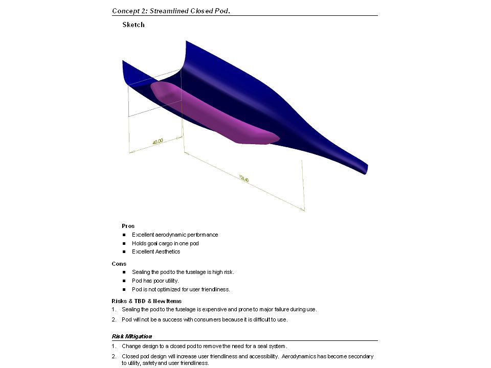
Pod Design Summary Follows Cirrus’ Method of Documentation Documents design requirements and goals. Documents the design concepts along with pros, cons, risks and mitigation. Documents the design process to provide insight to further investigation.

65
Pod Design Summary

68
Conclusions and Recommendations Gantt chart was useful for planning purposes Wiki was useful for common file sharing Requirements were recorded in a common location, a more stringent process would be useful. Schedule more time for risk mitigation Schedule more reviews during the design process Be more aggressive in achieving results and ensuring metrics are being met.

Similar presentations


Validation.>")


 Brian Martinez (Organizer) Mohammed Ramadan (Financial Officer) Noe Caro (Historian) SAE AERO Chase Beatty.>")


 Aircraft Progress Report Flavio Poehlmann-Martins & Probal Mitra January 11, 2002 MAE 439 Prof. R. Stengel Prof.>")
, fly (length) measurements. They all have a fly:hoist ratio of 1.9:1.>")