Download presentation
Presentation is loading. Please wait.

2
between molecules of a compound WEAK Within compounds STRONG

3
Strong electrostatic forces between ions Betw. Metal & Nonmetal Crystal lattice is formed Want to share electrons to achieve full outershell Molecules are formed. Betw. Two non-metals

4
Lewis structures use dots to represent outer shell electrons in atoms when they form molecules.

5
Calculate the total # of outer shell electrons Decide which atom is central (least electronegative) adding electrons to fill central atoms’ octet. Add electrons to give outside atoms full shells, any extra electrons, add to central atom. Form multiple bonds so central has octet Draw lines to represent one shared pair of electrons Rules for Drawing Lewis Structures

6
BF 3 B FF F Electron Deficit Atoms

7
B FF F Electron Deficient Atom: Boron does not have an octet N H H H These structures tend to attract other species with a non-bonded pair of electrons!

8
S F F F F F F I I I I 3 - Some nonmetals have more than Octet

9
Using oxidation numbers for assigning charges in molecules may be useful for redox reactions but can lead to an over estimation of actual charges. A more accurate charge assessment can be used in considering Lewis structures. FC is the difference between the number of valence electrons on the free atom and the number of valence electrons assigned to the atom in the molecule.

10
Calculating Formal Charge = (# valence electrons) -( # of Unshared electrons ) - ½(shared electrons)
 -( # of Unshared electrons ) - ½(shared electrons)")
11
N = 5 – 1 – ½(6) = +1 O = 6 - 4 – 1/2 (4) = 0 double bonded oxygen O = 6 – 6 – ½(2) = -1
 = +1 O = – 1/2 (4) = 0 double bonded oxygen O = 6 – 6 – ½(2) = -1")
12
Which structure is correct? The one with no formal charges, or the smallest formal charges! ( assign formal charges, now, to figure it out!)
.")
13
O - S = O O = S - O O S O This results in an average of 1.5 bonds between each S and O. Resonance structures Two different structures can be drawn.

14
Resonance structures Benzene, C 6 H 6, is another example of a compound for which resonance structure must be written. All of the bonds are the same length. or

15
Structure for Ozone

16
Resonance Structure for NO 3 - Arrows do NOT mean that the ion ‘flips’ from one to another, the actual structure is an average of the three!

17
The distance between two nuclei that includes the shared pair of electrons. The actual measured distance between the two nuclei is called the bond length. Includes the centers of + charge with a shared electrons in between. Double and Triple bonds make this length shorter than a single bond. However, in Nitrate Polyatomic Ion, the bond lengths are the SAME between all three nitrogen-oxygen!

18
Covalent Polar Covalent Polar Dative or Co-ordinate Bonding………

19
- + - + α- α- α + - +

20
How can the degree of polarity be predicted ? Use Electronegativites to make predictions about the type of bonding in a compound. The greater the difference in electronegativity of the two bonding elements, the greater is the chance for ionic bonding. The electronegativity difference between two covalently bonded atoms determines the polarity of the bond: The larger the difference, the more polar is the covalent bond. If the difference is zero or very small, the bond is essentially non-polar.

21
Difference in electronegativity 0.10.20.30.40.50.60.70.80.91.1.11.21.31.41.51.6 0.51246912151922263034394347 Percent ionic character % Difference in electronegativity 1.71.81.92.02.12.22.32.42.52.62.72.82.93.03.13.2 51555963677074767982848688899192 Percent ionic character %

22
We can use the difference in electronegativity between two atoms to gauge the polarity of the bonding between them Compound F2F2 HFLiF Electronegativity Difference 4.0 - 4.0 = 04.0 - 2.1 = 1.94.0 - 1.0 = 3.0 Type of BondNonpolar covalentPolar covalent Ionic (non- covalent)
")
23
Look at charts available on worksheets Table of Percent Ionic Character Topic 8 Bonding (Includes acceptable range)
")
24
Dative or Co-ordinate Bonding: Where one atom does not offer any electrons within the bond. Electrons are only offered by one atom. Oxygen commonly uses Dative Bonding.

25
Dipole Moments A method of describing charge concentrations. If an molecule has a clear center of positive charge away from a center of negative charge, it has a measured dipole moment.

26
(Molecule in electrical field) Arrow starts at LOWER electronegative atom!
 Arrow starts at LOWER electronegative atom!")
28
These dipoles cancel out, showing no effective charge on molecule.

29
Shapes of Molecules! Covalent: determined by the number of electron pairs around a central atom Remember: electron pairs REPEL each other! They will try to get away from each other! Valence Shell Electron Pair Repulsion Theory lists a set of shapes per # of electron pairs. VSEPR

30
*is based on the number of regions of high electron density around a central atom. *can be used to predict structures of molecules or ions that contain only non-metals by minimizing the electrostatic repulsion between the regions of high electron density. *can also be used to predict structures of molecules or ions that contain multiple bonds or unpaired electrons. *does fail in some cases. What Is VSEPR? The Valence Shell Electron Pair Repulsion (VSEPR) model:
 model:.")
31
VSEPR Rules 1.Draw the Lewis structure for the molecule or ion. 2. Count the total number of regions of high electron density (bonding and unshared electron pairs) around the central atom. a. Double and triple bonds count as ONE REGION OF HIGH ELECTRON DENSITY. b. An unpaired electron counts as ONE REGION OF HIGH ELECTRON DENSITY. c. For molecules or ions that have resonance structures, you may use any one of the resonance structures.
 around the central atom. a. Double and triple bonds count as ONE REGION OF HIGH ELECTRON DENSITY. b. An unpaired electron counts as ONE REGION OF HIGH ELECTRON DENSITY. c. For molecules or ions that have resonance structures, you may use any one of the resonance structures..")
32
3. Identify the most stable arrangement of the regions of high electron density as ONE of the following: linear trigonal planar tetrahedral trigonal bipyramidal octahedral

33
# regions of high electron density best arrangement description 2linear central atom and regions of high electron density arranged in straight line 3trigonal planar regions of high electron density directed at the corners of an equilateral triangle 4tetrahedral regions of high electron density directed at the corners of a tetrahedron 5trigonal bipyramidal three regions of high electron density directed at the corners of an equilateral triangle/one region of high electron density directly above the plane of the triangle and one directly below the plane 6octahedral regions of high electron density directed at the corners of an octahedron

35
Observe Chart on page 10 in Dingle Notes

36
Lesson 14 used VSEPR to describe molecular geometry. Water was described as linear, 109.5 o

37
Why isn’t waters’ structure Tetrahedral with bond angles of 109 o ? Because of the two lone pairs of electrons Reduces the bond angles

38
A step beyond VSEPR The localized Electron Model Electron Cloud Hybridization * describes how the role of orbitals can mold the shape of molecules sp 3, sp 2, sp, sp 3 d, sp 3 d 2 sigma and pi bonds and

39
How does hybridization happen?

40
Carbon in methane: CH 4 Consider Carbon: 1s 2 2s 2 2p 2 (1s 2 electrons don’t enter into the bonding) Bonding electrons: 2s 2 2p x 1 2p y 1 2p z 0 Since the first two electrons are in s orbitals, the other two electrons are in p orbitals, the shape of the clouds and the bonding angles should be different. But all four bond angles are actually the same!

41
2s 2 2p x 1 2p y 1 2p z 0 Carbon combines the s and three p orbitals into four new orbitals, so electron can be alone: If this arrangement is true, then the bond angles would all the same: 109 o, perfect tetrahedral. 1s 2 (sp 3 ) 1 (sp 3 ) 1 (sp 3 ) 1 (sp 3 ) 1 Carbon’s new electron configuration is: sp 3 sp 3
 1 (sp 3 ) 1 (sp 3 ) 1 (sp 3 ) 1 Carbon’s new electron configuration is: sp 3 sp 3.")
42
Ammonia HAS bond angles of 107 o NH 3 Nitrogen’s electron configuration: 1s 2 2s 2 2p x 1 2p y 1 2p z 1 If hydrogen bonded with each of the p’s, normally, then an angle of 90 o would be expected. So, there’s hybridization goin’ on… N’s NEW electron configuration: 1s 2 (sp 3 ) 2 (sp 3 ) 1 (sp 3 ) 1 (sp 3 ) 1 unshared pair ! (takes up more room!)
 2 (sp 3 ) 1 (sp 3 ) 1 (sp 3 ) 1 unshared pair . (takes up more room!).")
43
H 2 S bond angles are close to 90 o, what orbitals are involved? Sulfur: 1s 2 2s 2 2p 6 3s 2 3p 4 3p 4 = 3p x 2 3p y 1 3p z 1 Hydrogen’s 1s 1 ’s must bond in the two p’s of sulfur and since the angles are close to 90 o, safe to say NO hybridization is goin’ on.

44
Double and Triple Bonds provide some problems The REAL structure of a double bond is more complex and changes hybridization!

45
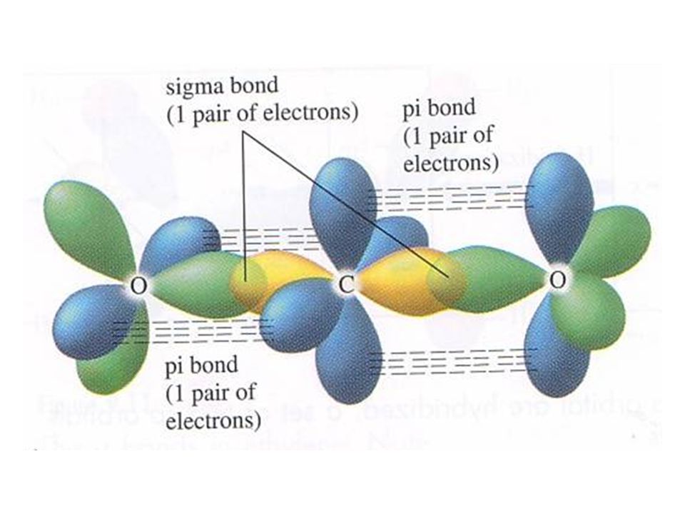
Sigma Bond Double bonds always consists of one pi and sigma bond pi Bond never hybridizes

46
sp 2 hybridzation Ethylene C 2 H 4 H 2 C = CH 2 Carbon: 1s 2 2s 2 2p x 1 2p y 1 2p z 0 Double bond counts as only one bond. The pi bond is NOT counted in hybridization! so there are only 3 bonds to consider! only the 2s and two p orbitals are used! 2s and 2p x and 2p y = sp 2

47
no pi bond shown here.

48
Trigonal planar arrangement = 120 o

49
sp hybridization Carbon Dioxide: CO 2 O = C = O Only two orbitals are affected and will hybridize Carbon: 1s 2 2s 2 2p x 1 2p y 1 2p z 0 Turns into: 1s 2 (sp) 1 (sp) 1 2p y 1 2p z 1 sigma bonds pi bonds
 1 (sp) 1 2p y 1 2p z 1 sigma bonds pi bonds")
51
sp 3 d hybridization PCl 5 Phosphorous provides 5 electrons to different atoms of Chlorine. P: 1s 2 2s 2 2p 6 3s 2 3p x 1 3p y 1 3p z 1 3d z2 0 (sp 3 d) 1 (sp 3 d) 1 (sp 3 d) 1 (sp 3 d) 1 (sp 3 d) 1 Uses one s, three p and one d orbitals = 5 WAS: s p p p d
 1 (sp 3 d) 1 (sp 3 d) 1 (sp 3 d) 1 (sp 3 d) 1 Uses one s, three p and one d orbitals = 5 WAS: s p p p d.")
52
sp 3 d 2 hybridization SF 6 Sulfur provides 6 electrons for bonding. S: 1s 2 2s 2 2p 6 3s 2 3p x 2 3p y 1 3p z 1 3d z2 0 3d x2-y2 0 (sp 3 d 2 ) 1 (sp 3 d 2 ) 1 (sp 3 d 2 ) 1 Uses one s, three p and two d orbitals = 6
 1 (sp 3 d 2 ) 1 (sp 3 d 2 ) 1 Uses one s, three p and two d orbitals = 6.")
54
(WEAK) H attached to N, O, F Attractions between dipoles Permanent dipoles Induced dipoles
 H attached to N, O, F Attractions between dipoles Permanent dipoles Induced dipoles")
55
Nuclear areas are left exposed in a Hydrogen molecule These exposed areas allow attractions to the + charged nucleus! These attractions are hydrogen bonds! These attractions are greatest between Hydrogen and nitrogen, fluorine or oxygen.

56
Hydrogen bonds are responsible for: A. High boiling points for substances that have them (water!) B. Substances with them are more viscous The increased attraction make it more difficult to separate the particles of these substances.
 B. Substances with them are more viscous The increased attraction make it more difficult to separate the particles of these substances..")
57
When molecules that have dipole moments come together, they will line themselves up using opposite ends.

59
Very small electrostatic forces that are formed formed when two molecules come close to each other, the electrons of the second molecule are repelled away from that end of the molecule to the end. This induces a pseudo + and pseudo – end in the molecule. These ends can act as temporary dipoles. Increase in Boiling points of moving down the Halogens, making them harder to separate.

61
A.Giant Atomic Structures B. Molecular Structures C. Ionic Structures D. Metallic Structures

62
A.Giant Molecular Structures Diamond and Graphite Carbon atoms bonded covalently in a continuous network!

63
Diamond based on Tetrahedral unit, graphite has a layered structure. All covalent bonds are strong and lend these molecules to have high melting and boiling points.

64
Cool properties of graphite: Conducts electricity in only one plane! Electrons move in one layer but not between layers. The layers are held together very weakly so the layers can be separated easily, making it a great lubricant.

65
B. Molecular Structures Iodine Some substances, like Iodine, are held in lattice structures by very weak dispersion forces. This provides Iodine with a low melting point. Iodine has no charged particles so it doesn’t carry an electrically current.

66
C. Ionic Structures Lattice structures created with charged particles. These substances are held together by strong bonds and have high melting and boiling points because of that. Hydration of these structures……….

67
D. Metallic Bonding A close-packed lattice of positive ions surrounded by a ‘sea’ of electrons.

Similar presentations


.>")


 ions and (-) ions 2. results when there is large electronegativity differences 3. generally.>")

