Download presentation
Presentation is loading. Please wait.

1
MOTORCYCLE TRACKING SECURITY SYSTEM (M.T.S SYSTEM) Group 8 Andres F. Suarez (EE) Brian Maldonado (EE) Rígel Jiménez (EE)
 Brian Maldonado (EE) Rígel Jiménez (EE).")
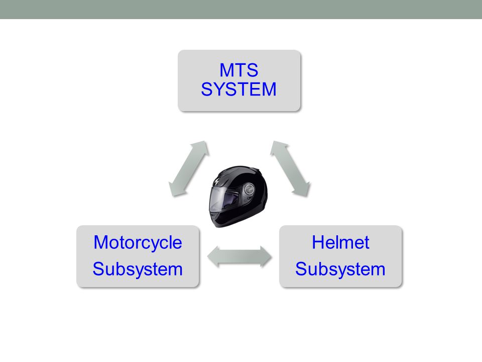
2
Motivation According to the National Highway Traffic Safety Administration (NHTSA), there were over 9 million motorcycles registered in 2012 in the US. Unfortunately, the basic motorcycle lacks securities and technological features available in some other transportation vehicles. The MTS system is about to change this because it will significantly enhance the motorcycle riding experience, by adding: Security Features Bluetooth capabilities Ability to text an emergency contact Tracking motorcycle location 24/7 MTS

3
Goals and Objectives Adding electrical components to the helmet without significantly increasing the weight. Keeping the helmet as spacious as it was originally, even though it will now have all the electronic components. Being able to synchronize the helmet to a cell phone. Providing security features to the helmet and the bike. Implementing an accelerometer to the bike and helmet. The system should be able to send text messages.

4
Specifications

6
Motorcycle Subsystem

7
Helmet Subsystem

8
Motorcycle Accelerometer Module

9
ADXL345 Accelerometer

10
ADXL345 Functions

11
Accelerometer Registers and Functions Registers 8-bit register addresses ranging from 0x00 to 0x39 Sets the specs for the interrupts and contains serial, and bandwidth selection. Contains a total of 14 different interrupt functions.

12
GPS Module

13
LS20031 GPS Module

14
LS20031 GPS Pin Assignment and Descriptions

15
GSM Module

16
SM5100B GSM Module APPLICATION: Sends SMS text messages with corresponding GPS coordinates. FEATURES: Dimensions: 35.0 x 39.0 x 2.9mm. Power: 3.3 – 4.2 V. Nominal 3.6 V. Current consumption: <100μA when module is off; and 2 mA in Sleep mode. Quad-band GSM. Frequency Bands: 900,850,1800,1900 MHz. Supports UART interfaces. Supports SIM (Auto Recognize). Soldered connection for antenna. LED to notify network status.
. Soldered connection for antenna. LED to notify network status..")
17
SM5100B Functional Block Diagram

18
MCU

19
Microcontroller Selection Primary means of control between system and subsystem peripherals. Soft Serial Library included to communicate with multiple devices. ATMEL ATmega328

20
RF Module

21
RF Device Selection

22
Further Selection

23
XBee 2.4 GHz RF Module

24
XBee Functionality Point-to-point communication between the motorcycle system and the helmet system.

25
Motorcycle Battery

26
Motorcycle Power Source The stock 12V battery will be used to power the motorcycle subsystem. Two different states of power consumption.

27
Motorcycle Power Source Motorcycle off: power consumption < 100mA No parasitic draw!

28
Bluetooth Module

29
RN-52 Bluetooth Audio Module Wireless communication used to connect the MTS system to a cell phone (Supports iAP profile) Bluetooth 3.0 class 2 Audio Module UART console interfaces Operation range: 10 meters (33 feet) Supplied voltage: 3.0 ~ 3.6 V DC Dimensions: 26.0 x 13.5 x 2.7 mm Frequency band: 2.4 ~ 2.48 GHz Maximum Data Rate: 3Mbps Embedded Stack Profiles: A2DP, AVRCP Built-in Antenna
 Bluetooth 3.0 class 2 Audio Module UART console interfaces Operation range: 10 meters (33 feet) Supplied voltage: 3.0 ~ 3.6 V DC Dimensions: 26.0 x 13.5 x 2.7 mm Frequency band: 2.4 ~ 2.48 GHz Maximum Data Rate: 3Mbps Embedded Stack Profiles: A2DP, AVRCP Built-in Antenna")
30
RN-52 APPLICATIONS High-quality, 2-channel audio streaming. Wireless stereo headsets. Wireless speakers. Intercom push-to-talk audio connection Automotive hands free audio Remote control for media player. Computer accessories

31
Accelerometer Module

32
Helmet Accelerometer Alarm Engaged Functions as a motion sensor for the helmet. Has a set threshold for detecting Activity. When threshold passed, interrupt signal is sent to the microcontroller.

33
Helmet Battery

34
Helmet Power Source Polymer Lithium Ion Battery- 1000 mAh Cell outputs at a nominal 3.7V. Standard discharge current of 200 mA to 2000 mA and Charge current of 200 mA to 1000 mA. Battery includes built-in protection against over voltage, over current, and minimum voltage. Requires a specialized lithium polymer charger.

35
Helmet Recharge Circuit Lithium Polymer Batteries require special charging If not charged the proper way it could ruin the battery Lithium Ion/Polymer USB Battery Charger IC - MAX1555 External Supply of 3.7V to 7V Will recharge battery through USB connection Max current charge of 300 mA

36
Scenario 1-Motorcycle Theft Accelerometer Threshold passed Sends Interrupt to Microcontroller Microcontroller Wakes up GPS, GSM to full active mode GPS Retrieves location and sent to the microcontroller. Decode Micro decodes NMAE packet into latitude and Longitude GSM Receives coordinates with message Sends SMS to owner

37
Scenario 2-Accident This Scenario follows the same steps as scenario 1 with added functions. Emergency Response Receives emergency text from MTS. Bluetooth Can receive Phone Call, kind of like OnStar Assess If able to receive call can inform situation, if not WCS assumed.

38
Scenario 3-Helmet Theft H. Accelerometer Threshold passed Sends Interrupt to Microcontroller H. Microcontroller Sends signal to main Micro through RF M. Microcontroller Receives RF signal Wakes up GPS, GSM to full active mode GPS Retrieves location and sent to the microcontroller. Decode Micro decodes NMAE packet into latitude and Longitude GSM Receives coordinates with message Sends SMS to owner

39
Distribution of Work Load

40
Milestone

41
Budget

42
Difficulties Selecting modules very hard to solder and availability of parts. Interfacing multiple serial devices to our microcontroller.

43
Questions?

Similar presentations


 4 Line by 18 Character fully.>")


 Group 8 Andrés F. Suárez (EE) Brian Maldonado (EE) Rígel Jiménez (EE)>")

 2.VEERNAPU SURI BABU (CS12B1039) GSM BASED SMS CONTROLLER.>")


