Download presentation
Presentation is loading. Please wait.

1
CHAPTER 7 Broadband ATM networks

2
topics Introduction Cell format and switching principles Switch architecture Protocol architecture ATM LAN’s

3
Introduction Broadband ISDN Cells ATM( asynchronous transfer mode) Virtual circuit- VCI
 Virtual circuit- VCI")
4
Broadband ATM networks- Introduction B-ISDN –designed to support multimedia applications Each call involves different types of media The txn & switching system is independent of both bit rate & source information Cells- small fixed sized packets Cell switching

5
Instead of allocating a fixed portion of transmission bandwidth per call, Streams related to different calls are multiplexed together on a statistical basis The switching units then operate using a form of packet switching - cell switching Higher rate of switching -fast packet switching Cells relating to different calls have varying time intervals asynchronous transfer mode (ATM) CO mode-header size is small
 CO mode-header size is small")
6
Virtual path switching Virtual path switching is when multiple calls originating at the same network entry point are all intended for the same destination exit point. Each individual call is assigned a separate VCI and the calls are multiplexed together at the source interface onto a single virtual path. The multiplexed set of calls are then switched using the VPI field only and hence all follow the same path through the network.

7
A Virtual Circuit Identifier (VCI) is a unique identifier which indicates a particular virtual circuit on a network. It is a 16-bit field in the header of an ATM cell. The VCI, together with the Virtual Path Identifier (VPI) is used to identify the next destination of a cell as it passes through a series of ATM switches on its way to its destinationvirtual circuitATMVirtual Path Identifier
 is used to identify the next destination of a cell as it passes through a series of ATM switches on its way to its destinationvirtual circuitATMVirtual Path Identifier.")
8
Virtual circuit a packet switched CO mode involves, Path establishment Path termination This path is called virtual circuit a virtual circuit (VC), synonymous with virtual connection and virtual channel, is a connection oriented communication service that is delivered by means of packet mode communicationvirtual channelconnection oriented packet mode
, synonymous with virtual connection and virtual channel, is a connection oriented communication service that is delivered by means of packet mode communicationvirtual channelconnection oriented packet mode")
9
Virtual Paths and Virtual Channels ATM networks are fundamentally connection oriented. This means that a virtual connection needs to be established across the ATM network prior to any data transfer. ATM virtual connections are of two general types: Virtual path connections (VPCs), identified by a VPI. Virtual channel connections (VCCs), identified by the combination of a VPI and a VCI. Every cell header contains a VPI field and a VCI field, which explicitly associate a cell with a given virtual channel on a physical link.
, identified by a VPI. Virtual channel connections (VCCs), identified by the combination of a VPI and a VCI. Every cell header contains a VPI field and a VCI field, which explicitly associate a cell with a given virtual channel on a physical link..")
10
ATM Virtual Path And Virtual Channel Connections A virtual path is a bundle of virtual channels,. A VPC can be thought of as a bundle of VCCs with the same VPI value

11
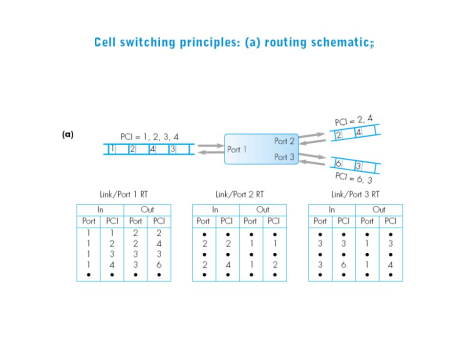
Cell format Prior to any info. Cells being sent, a virtual circuit is first established. In an ATM network, the VCI used on each link is known as the protocol connection identifier (PCI). PCI- 2 sub fields 1. virtual path identifier (VPI) 2. virtual circuit identifier( VCI)
. PCI- 2 sub fields 1. virtual path identifier (VPI) 2. virtual circuit identifier( VCI).")
14
Virtual channel switching The use of virtual channel switching is when each call at the network entry point is intended for a different destination. Each call is again assigned a different VCI but switching is also performed using the VCI field.

16
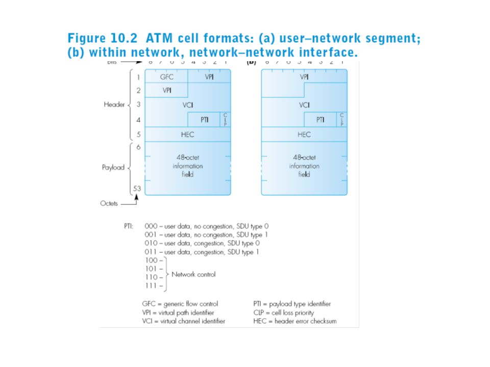
ATM cell format Generic flow control (GFC)- present only in cells transferred over the UNI enables a local switch to regulate –flow control- the entry of cells by a user into the network. Virtual path identifier (VPI) – 8 bits at the UNI, 12 bits at the NNI. Used for identification/routing purpose within the network. Virtual channel identifier (VCI) – 16 bit field Used for identification/routing purpose within the network.
 – 8 bits at the UNI, 12 bits at the NNI. Used for identification/routing purpose within the network. Virtual channel identifier (VCI) – 16 bit field Used for identification/routing purpose within the network..")
17
ATM cell format Payload type indicator (PTI) – indicates the type of info. Carried in the cell. Cell loss priority (CLP)- to enable the user to specify a preference as to which cells should be discarded. Header error checksum (HEC)- generated by the physical layer, 8 bit CRC on the first byte of the header.
- to enable the user to specify a preference as to which cells should be discarded. Header error checksum (HEC)- generated by the physical layer, 8 bit CRC on the first byte of the header..")
19
user–network segment

20
network–network interface

21
PTI

23
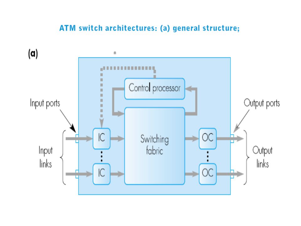
Switch architecture Each input link is terminated by input controller (IC). IC performs the routing of cells.It involves a simple look –up and mapping operation. Cells may require same output port/link. Handled in two ways:1.IC has buffers 2. OC has buffers. Main role of control processor- download routing info. Into routing tables in each input controller. Also generates n/w management reports.

24
Switch fabric Time division switch We use a time division backplane bus Transfers N cells( N- no. of i/p ports) in a single cell arrival time. Space division switch- The switch fabric comprises a matrix of interconnected switching elements that collectively provide a no. of alternative paths through the switch. (known as fully connected switch matrix)-non blocking.
 in a single cell arrival time. Space division switch- The switch fabric comprises a matrix of interconnected switching elements that collectively provide a no. of alternative paths through the switch. (known as fully connected switch matrix)-non blocking..")
25
A switching matrix that comprises multiple switching stages is the delta switch matrix. No. of switching elements per stage X= M/N No of stages, N^y= M. Associated with each switching element is a control routing bit called routing tag bit. If routing tag bit=0, cell is routed to the upper o/p. If 1, cell is routed to the lower o/p.

31
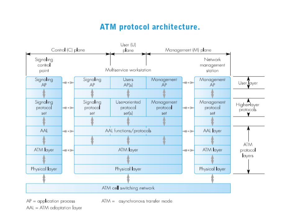
Protocol architecture ATM protocol architecture supports 3 separate application functions (planes). C plane, M plane and U plane. The protocols associated with c plane are concerned with signaling. The protocols in the u plane depend on the application, communicate on a user to user basis with a similar protocol set in the destination station. M plane – management.

32
ATM network supports a range of different services. To achieve this, there are 3 ATM layers: ATM adaptation layer (AAL) ATM layer Physical layer.
 ATM layer Physical layer..")
33
Functions of each layer AAL layer- provides a range of service types knonw as service classes. each service class has a different protocol associated, which converts the source info. Into 48 octet segments. Passes to the ATM layer for transfer across the n/w. ATM layer – adding the correct cell header to each segment amd multiplexing.

34
Physical layer- Transmission convergence sublayer- generation of header check sequence in the cell header Medium dependent sublayer- line coding and bit clock synchronization.

35
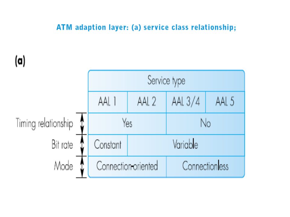
AAL layer 5 service types defined: AAL1-5 AAL1 ( class A) Connection oriented Constant bit rate service. Sequence no. is for detection of lost segment. SN-sequence no. protection- protect the seq.no. against single bit errors. Convergence sublayer indication bit-transfer of timing info. Relating to the payload field.

38
AAL2 Timing relationship between source and destination SAPs Burst of Info. occurs, with each burst containing a variable rate of info. The format of each PDU is shown. Seq no. IT (information type field)- BOM (beginning of message), COM and EOM.
- BOM (beginning of message), COM and EOM..")
39
The last EOM may not be full. LI (length indicator) at the tail indicates the no. of useful bytes in the segment. FEC enables bit errors to be detected.

41
AAL 3/4 AAL3 was initially designed to provide a connection oriented data service. This type of service was dropped and combined with AAL4. Connectionless data transfer service Variable length frames up to 65535 bytes. The format of PDUs associated with CS and SAR are different.

44
Type field =0, with AAL3/4 BE tag is a modulo 256 seq. no. – enables SDUs to be delivered at the user interface in the same sequence as they were submitted. BA (buffer allocation) to allocate an appropriate amount of buffer for the complete SDU. Pad field – to make the total no.of octets an integral multiple of 4 octets. Alignment is a single dummy octet. Length field- total length of the complete PDU.
 to allocate an appropriate amount of buffer for the complete SDU. Pad field – to make the total no.of octets an integral multiple of 4 octets. Alignment is a single dummy octet. Length field- total length of the complete PDU..")
45
AAL5 SEAL (simple and Efficient adaptation layer)– provided similar service as AAl3/4 with reduced no. of control fields in both CS and SAR PDUs. AAL user to user identifier(UUI) enables the two correspondent user layers to relate the AAL SDU to a particular SAP. AAL5 is also used as the AAL layer in the c plane for the segmentation and reassembly of messages associated with the signaling protocol.- signaling AAL or SAAL.
 enables the two correspondent user layers to relate the AAL SDU to a particular SAP. AAL5 is also used as the AAL layer in the c plane for the segmentation and reassembly of messages associated with the signaling protocol.- signaling AAL or SAAL..")
46
ATM layer Functions: Performs all the functions relating to routing and multiplexing of cells over VCs. Assign a header to the segment streams. On receipt of streams, remove the header from each cell and pass the cell contents to the appropriate AAL layer protocol.

47
Service classes ATM layer offers various service classes in a public network: CBR- ex. Uncompressed speech, video. VBR/RT VBR/NRT ABR UBR

48
Associated with each service class is a network QoS guarantee which forms the basis of contract b/w the n/w provider and the n/w user. The parameters relating to user : Peak cell rate(PCR)- the max. rate the source will enter cells. Sustained cell rate (SCR)- the average rate the source will enter cells. Minimum cell rate (MCR)- the minimum cell rate that is acceptable by source. Cell delay variation tolerance (CDVT)- the max. level of variation in intercell times.
- the max. rate the source will enter cells. Sustained cell rate (SCR)- the average rate the source will enter cells. Minimum cell rate (MCR)- the minimum cell rate that is acceptable by source. Cell delay variation tolerance (CDVT)- the max. level of variation in intercell times..")
49
The parameters relating to n/w : Cell loss ratio (CLR)- the max. ratio of cells undelivered. cell transfer delay (CTD)- the avg transfer delay of cells across the n/w Cell delay variation (CDV)- the avg variation in cell transfer delay. Generic cell rate algorithm( GCRA)- for each cell entered into the n/w and to be delivered, the n/w determines whether the parameters for this call conform to the agreed contract.
- the avg transfer delay of cells across the n/w Cell delay variation (CDV)- the avg variation in cell transfer delay. Generic cell rate algorithm( GCRA)- for each cell entered into the n/w and to be delivered, the n/w determines whether the parameters for this call conform to the agreed contract..")
50
Principle of operation of generic cell rate algorithm

51
ATM LANs Designed to meet the high BW requirements of MMC applications. Alternative to LANs based on fast ethernet. ATM LANs are introduced in a incremental way. Majority of LAN installations are of ethernet type. Legacy LANs.

52
Components of ATM LAN: RCU (remote concentrator unit) Virtual connection (VC) Broadcast server-enables a user at a MMC workstation to set up on demand video conferencing session Signaling control point (SCP)- central control unit to set up VC on demand by the user. All the signaling messages for the set up/clear of calls are transferred across the n/w through SCP in the form of cells over separate VCs that are set up permanently for this function- signaling virtual channel connections(SVCC).
..")
53
To access networked servers which are very lage in no. permanent VCs are set up b/w all user stations and servers and a central data forwarding point called connectionless server (CLS). This is similar to service provided by broadcast LAN and hence called LAN emulation server (LES). Network management station- permanent VCs are set up under the overall control of n/w management station.
. This is similar to service provided by broadcast LAN and hence called LAN emulation server (LES). Network management station- permanent VCs are set up under the overall control of n/w management station..")
54
ATM LAN schematic

55
Types of call Connection oriented Connection less- When using bridges, routing is carried out at the MAC sub layer. When using routers, routing is carried at the IP/IPX layer. Both MAC and IP layers provide a best effort connectionless service for the transfer of datagrams.

56
LAN emulation The method used when bridges are used in the legacy LAN. The aim is to emulate the broadcast mode of operation of a legacy LAN over a connection oriented ATM LAN. The 3 components used are: LECS- LAN emulation configuration server LES- LAN emulation server BUS- broadcast and unknown address server.

57
LECS is used by all stations to determine the TAM address of the LES and BUS. The BUS is responsible for multicasting/broadcasting and for relaying frames to stations whose MAC address is known by the LES. LEC( LE client) comprises hardware and software that provides a similar service to the MAC chipset. The VC that connects (logically) an LEC to LES – control direct VCC.
 comprises hardware and software that provides a similar service to the MAC chipset. The VC that connects (logically) an LEC to LES – control direct VCC..")
58
LAN emulation: (a) terminology and networking components;
 terminology and networking components;")
59
Classical IP over ATM(IPOA) The method used when subnet routers form the interface to the legacy LAN. ARP in the classical IP. IP/MAC address pair ARP in ATM IP/ATM address pair Streaming or pipelining.

60
Protocol architecture to support classical IP over an ATM LAN

Similar presentations


. 2 ATM - An Overview of ATM A technology for multiplexing fixed-length cells from a variety of sources to a.>")

 ATM is a specific asynchronous packet-oriented information, multiplexing.>")

 All rights reserved by Professor Wen-Tsuen Chen 1 Asynchronous Transfer Mode (ATM)>")
>")

 Broadband Integrated Service.>")


 Abdullah AL-Harthi.>")
 Cell Switching Connection-oriented packet-switched network Used in both WAN and LAN settings Signaling (connection setup)>")

>")