Download presentation
Presentation is loading. Please wait.

1
Drip System Approvals: County Perspective October 19, 2010 2010 Onsite Water Conference Anne Lowry, REHS Chatham County Environmental Health

2
Drip System Siting Criteria Drip System Sizing Drip System Design Criteria Drip System Installation & Testing Drip System Operation, Maintenance, and Monitoring Requirements

3
Soils 18-20”: – Fill System – Anaerobic Drip Type of Drainfield Fill System

4
Only American Manufacturing (Perc-Rite) has approval for Anaerobic drip system. Anaerobic Drip Systems **(Anaerobic drip is designed without pretreatment)
.")
5
Siting Criteria for Anaerobic Drip Systems Requires: Minimum of 18” of useable naturally occurring soil above an UNSUITABLE soil horizon, rock, or a soil wetness condition. 12” vertical separation from bottom of trench to UNSUITABLE soil horizon, rock, or soil wetness condition. A special site evaluation if Group IV soils are encountered within 18” of the naturally occurring soils surface.

6
Siting Criteria for Anaerobic Drip Systems 18” Suitable Soil Group IV soils within 18” (need special site evaluation) Installation depth 6” 12” vertical separation
 Installation depth 6 12 vertical separation")
7
Drip Video

8
Soils 13-18”: Pretreatment with drip disposal Type of Drainfield

9
Pretreatment Options Gravel Bed Peat Filter Fabric Filter Sandfilter Pretreatment Units

10
Effluent Treatment Standard Minimum Soil Depth Vertical Separation Distance NSF 4018”12” TS I15”9” (12” for rock or tidal water) TS II13” (for Perc Rite) 15” for Geoflow 6” (12” for rock or tidal water) Aerobic Drip Siting Criteria Pretreatment Drip Soil Depth Requirements:
 TS II13 (for Perc Rite) 15 for Geoflow 6 (12 for rock or tidal water) Aerobic Drip Siting Criteria Pretreatment Drip Soil Depth Requirements:")
11
Aerobic Drip Siting Criteria 13’ 18” NSF 40 Geoflow Perc Rite 15”

12
Aerobic Drip Siting Criteria Horizontal Setbacks: Public water supply WS-1 Streams & S.A. Waters Other Coastal Waters Streams, canals surface water Drainage systems: upslope/sideslope/ downslope Any other nitrification field.1900 Rules 100 50 10, 15, 2520 NSF 401007035 10, 15, 2520 TS I1007035 7, 10, 2010 TS II1005025 7, 10, 1510

13
Aerobic Drip Siting Critera Reductions in horizontal and vertical setbacks cannot be taken concurrently when installing drip systems except for drainage systems setbacks (interceptor, foundation drains, diversion)
")
14
Aerobic Drip Sizing Special Site Evaluation Detailed descriptions of soil profiles and soil morphological Description of landscape position Location and depth for placement of the trenches Recommended LTAR Hydraulic conductivity tests, lateral flow analysis, Proposed site-specific requirements for system design, installation, site preparation, modifications, Additional Special Site Evaluation Requirements in.1970 (p)(2)
(2)")
15
Aerobic Drip Sizing Drip systems treated to TS I or more stringent standard on sites with less than 18” of suitable soil shall not exceed the lowest LTAR of the soil group: Soils GroupLTAR Maximum w/ Reduced setbacks (horizontal or vertical) Group I.8 Group II.5 Group III.2 Group IV.1
 Group I.8 Group II.5 Group III.2 Group IV.1")
16
Aerobic Drip Sizing Minimum square footage: – Design daily flow ÷ LTAR = Square footage – Ex. 360 design flow ÷.1LTAR = 3600 sq.ft.

17
Aerobic Drip Sizing Minimum drip tubing length: Square Footage ÷ 2 Feet = Drip tubing length Ex. 3600 Sq.Ft. ÷ 2 Feet = 1800’ Drip tubing length

18
Aerobic Drip Design Criteria Requires: Pretreatment prior to drip emitter system to reduce BOD and TSS to 30mg/l each. Dosing tank must be the same size as is required for the septic tank. Floats must be adjustable from ground surface with out entering tank. Must have audio visual alarm. Must have self cleaning filters

19
Pretreatment Options Gravel Bed Peat Filter Fabric Filter Sandfilter Aerobic Drip Design Criteria Pretreatment prior to drip emitter system to reduce BOD and TSS to 30mg/l each.

20
Aerobic Drip Design Criteria Floats adjustable from ground surface

21
Aerobic Drip Design Criteria Audio/Visual Alarm

22
Self Cleaning Filters Disc Filter Screen Filter

23
Headworks

24
Aerobic Drip Design Criteria Processing and Control Unit Requires: – Must be able to be programmed to deliver design volumes to each field at specified intervals (flow equalization) – Must include automatic flushing of filters and laterals – Must have ETM and CC for each zone – Must keep record of flow – Must be 36” above grade – Telemetry if design flow is above 600gpd
 – Must include automatic flushing of filters and laterals – Must have ETM and CC for each zone – Must keep record of flow – Must be 36 above grade – Telemetry if design flow is above 600gpd")
25
Control Panel

26
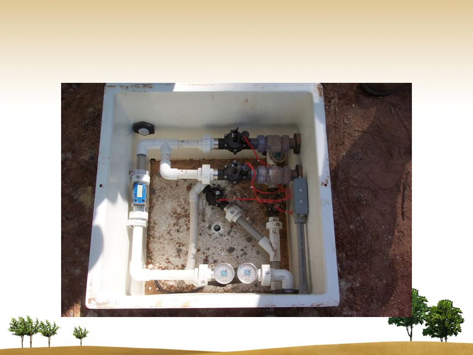
Aerobic Drip Design Criteria Headworks Box The Headworks box includes filters, backwash valves, field flush valve and flow meter. Headworks components shall be in a separate enclosure that is freeze protected, UV and corrosion resistant Design shall facilitate reasonable access to all internal components.

28
Aerobic Drip Design Criteria Drip Field Design Drip tubing shall have pressure compensating emitters Drip tubing shall effectively inhibit root growth Pressures must be able to maintain a minimum of 7-60psi during dosing

30
Aerobic Drip Design Criteria Drip Field Design Lines shall be installed level +/- 2” in any linear segment on 2’ centers. May reduce center to center spacing to 1.5’ to avoid field obstructions (trees, rocks) Connection lines shall be conveyed over earthen dams with at least 2” higher than drip lines. When slopes exceed 10% check valves shall be used in supply and return manifolds.
 Connection lines shall be conveyed over earthen dams with at least 2 higher than drip lines. When slopes exceed 10% check valves shall be used in supply and return manifolds..")
31
Aerobic Drip Design Criteria Drip Field Design Scour velocity of 1.2 feet per second minimum during dosing & flushing Minimum pressure of 10psi during flushing ?? Maximum of 60 psi during dosing Air vent, check valve, solenoid valves at high point of each zone. Pressure monitoring fittings at field inlet and outlet Valves & cleanouts shall have protective vaults/boxes

32
Schrader Valves in Field to check pressure head in field

33
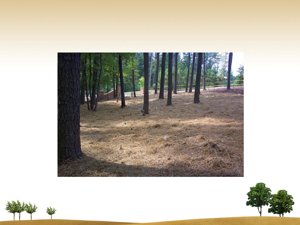
Drip System Installation

34
Aerobic Drip Installation & Testing Procedures Preconstruction conference required – Local Health Department – Engineer (Manufacturer Authorized) – System Designer (Manufacturer Authorized) – Grade Level IV Installer (Manufacturer Authorized) – Licensed Soil Scientist
 – System Designer (Manufacturer Authorized) – Grade Level IV Installer (Manufacturer Authorized) – Licensed Soil Scientist")
35
Aerobic Drip Installation & Testing Procedures All tanks are to be water tested into risers Field must be flagged prior to installation 6” minimum soil cover over drip tubing

38
Aerobic Drip Installation & Testing Procedures Blanking: – Blanking sections are not be included in linear footage total – 6” of soil cover must be maintained over blanking sections. – Blanking should be installed at same elevation as drip tubing If blanking is not able to maintain same elevation then the blanking shall go above in elevation around obstruction.

40
Aerobic Drip Installation & Testing Procedures Start up attendees: – Local Health Department – Engineer (Manufacturer Authorized) – System Designer, if applicable (Manufacturer Authorized) – Grade Level IV Installer (Manufacturer Authorized) – Licensed Soil Scientist – Operator in Responsible Charge
 – System Designer, if applicable (Manufacturer Authorized) – Grade Level IV Installer (Manufacturer Authorized) – Licensed Soil Scientist – Operator in Responsible Charge")
41
Aerobic Drip Installation & Testing Procedures EngineerLSSInstallerORC

42
Aerobic Drip Installation & Testing Procedures Start up: – Conduct required start up checks on pretreatment unit. – Check alarms (audio/visual) for dosing tank and recirculation tank, if applicable – Check grade around tanks – Check UV light, if applicable – Check Headworks box
 for dosing tank and recirculation tank, if applicable – Check grade around tanks – Check UV light, if applicable – Check Headworks box.")
45
Aerobic Drip Installation & Testing Procedures Start up: Supply line shall be flushed prior to start up Run each zone dosing and flushing at design times Measure flow rates during dosing and flushing Measure field pressures during dosing and flushing Walk field during dosing and flushing to verify no leaks

46
Aerobic Drip Installation & Testing Procedure Start up: Vegetative cover must be established over field Check for settled areas over drip tubing, add soil as needed Finished grade shall allow for shedding of surface water

48
Aerobic Drip Installation & Testing Procedures Prior to issuing Operation Permit: Maintenance contract signed by manufacturer approved ORC and property owner must be submitted to the LHD Engineer/Designer must submit written certification that system was installed as designed. Manufacturer/Manufacturer Representative must submit confirmation of their acceptance of the system installation. Licensed Soil Scientist must submit written certification that the installation was in accordance with their specified site/installation requirements.

49
Aerobic Drip Operation, Monitoring, & Maintenance Inspection frequency for the first year is quarterly, two times per year there after Inspections shall include: Flushing rates & pressuresDocument flow meter Checking/cleaning filtersDocument ETM & CC Measure dosing rate to each zoneVisual observation of drip field

51
Questions??

Similar presentations


A new, replacement, or repaired septic.>")

. Sewer Basics Collection and transport of wastewater from each home/building to the point where treatment occurs.>")


 Session 4: Design and Plan Review— Conventional Systems Part.>")


