Download presentation
Presentation is loading. Please wait.

1
ADJUSTMENT COMPUTATIONS
STATISTICS AND LEAST SQUARES IN SURVEYING AND GIS PAUL WOLF CHARLES D. GHILANI

2
TRAVERSE CLOSURE √ ΔX2 +ΔY2 =Distance Error Distance Error/ Total Distance = Error per foot Or Error Ratio Tan -1 (ΔY / ΔX) = Angular Error (Azimuth)
 = Angular Error (Azimuth)")
3
ACCURACY VS. PRECISION PRECISE BUT NOT ACCURATE PRECISE AND ACCURATE
REPEATABILITY TO CONFORM TO THE STANDARD The target on the left could be acceptable if proper steps are taken to correct for the presence of systematic errors. (This is equivalent to a marksman realigning the sights after the shots.) PRECISE BUT NOT ACCURATE PRECISE AND ACCURATE
 PRECISE BUT NOT ACCURATE. PRECISE AND ACCURATE.")
4
ACCURACY VS. PRECISION ACCURACY-the degree of conformity with a standard or measure of closeness to a true value. An exact value, such as the sum of three angles of a triangle equals 180° A value of a conventional unit by physical representation, such as U.S. Survey foot. A survey or map deemed sufficiently near the ideal or true value to be held constant for the control of dependent operations. Accuracy relates to the quality of the result obtained when compared to the standard. The standard used to determine accuracy compared to the true value. Can the true value be determined? No. Error is always present in all measurements. How much is determined by several factors.

5
ACCURACY VS. PRECISION Precision – the degree of refinement in the performance of an operation (procedures and instrumentation) or in the statement of a result. Applied to methods and instruments used to attain a high order of accuracy. The more precise the survey method, the higher the probability that the results can be repeated.
 or in the statement of a result. Applied to methods and instruments used to attain a high order of accuracy. The more precise the survey method, the higher the probability that the results can be repeated.")
6
ACCURACY VS. PRECISION Survey observations can have a high precision, but still be inaccurate. Poorly adjusted instrument Poor methods and procedures Instrument set up Not checking work Human error

7
STANDARDS National Geodetic Control Networks are based on accuracy.
Consistent with the network not just a particular survey Not the mathematical closure but the ability to duplicate established control values

8
READING ERRORS Repetition reading instrument
Repetition Method Circle is zeroed Reading errors σαr = √σo2 + σr2 n σσr - Estimated Standard Error in the average angle due to reading σo - estimated error in setting zero σr - estimated error in the final reading n – number of repetitions Standard deviation- square root of the sample variance. 68% of the time measurement will fall within this standard. Square the Sum of the difference between the measurement and mean Divided by the number of repetitions minus one.

9
READING ERRORS Ability to set zero and read the circle equal

10
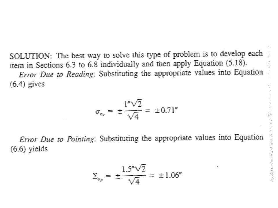
READING ERRORS σαr = ±1.5√2 = ±0.4” 6 Example: Repetition Method
Suppose an angle is read six times using the repetition method. An operator having a personal reading error of ±1.5”, what is the estimated error in the angle due to circle reading? σαr = ±1.5√2 = ±0.4” 6

11
READING ERRORS Direct Method σαr = σr√2 √ n
Backsight and Foresight readings Angle is difference between to readings Multiple measurements σαr = σr√2 √ n σσr - Estimated Standard Error in the average angle due to reading σr - estimated error in the final reading n – number of repetitions

12
READING ERRORS σαr = ±1.5√2 = ±0.9” √6 Example: Direct Method
Suppose an angle is read six times using the direct method. An operator having a personal reading error of ±1.5”, what is the estimated error in the angle due to circle reading? σαr = ±1.5√2 = ±0.9” √6

13
POINTING ERRORS SEVERAL FACTORS AFFECT ACCURACY
OPTIC QUALITIES TARGET SIZE OBSERVER’S PERSONAL ABILITY TO PLACE CROSSHAIRS ON THE TARGET WEATHER CONDITIONS POINTING ERRORS ARE RANDOM THEY WILL OCCUR POINTING ERRORS NOT DEPENDENT ON INSTRUMENT. Pointing errors occur at each back sight and fore sight, the pointing error will be the mean of the number of repetitions

14
POINTING ERRORS Assume for any given instrument and observer the pointing error can be the same for each repetition. σαp = σp√2 √ n

15
POINTING ERRORS Example:
Suppose an angle is read six times by an operator whose ability to point on a well-defined target is estimated to be ±1.8”, what is the estimated error in the angle due to pointing? σαp = ±1.8√2 = ±1.0” √6

16
TOTAL STATIONS DIN NUMBER (DIN 18723) Deutsches Institut fϋr Normung
DIN accuracy is not inferred from the least count Example of DIN use Accuracy according to DIN of 5” in a face 1 and face 2 direction Standard Deviation of a Face 1 and Face 2 reading is ±5” Standard Deviation of an angle σ =√2 * 5” = 7” DIN is associated with statements of accuracy of theodolites since the introduction of electronic theodolites. DIN loosely translated German Institute for standards. Least count- with the advent of electronic instruments, reliance on the least count for anything but an estimate of precision achievable (not accuracy) is highly inadvisable.
 is highly inadvisable.")
17
What is a mgon? milligon 1 grad = 1,000 mgon = 54’ of arc 1 mgon = 3.24” of arc= grad

18
TRAVERSE BY TOTAL STATION
POSSIBLE SOURCES OF ERROR READING ERRORS SET UP ERRORS INSTRUMENT AND REFLECTOR POINTING ERRORS INSTRUMENT LEVELING ERRORS MEASUREMENT ERRORS BY EDM Errors are always introduced in all instruments measuring distances and angles. Small or large depending on the operator, instrument and conditions at the time of measurement. Each source produce a small amount of random error.

19
TOTAL STATION ESTIMATED POINTING AND READING ERROR σαpr = 2σDIN √n

20
Example: An angle is read six times (3 direct and 3 reverse) using a total station having a published DIN value for pointing and reading of ± 5” . What is the estimated error in the angle due to pointing and reading? σαpr = 2 * 5” = ± 4.1” √6
 using a total station having a published DIN value for pointing and reading of ± 5 . What is the estimated error in the angle due to pointing and reading σαpr = 2 * 5 = ± 4.1 √6.")
21
TARGET CENTERING ERRORS
Setting a target over a point Weather conditions Optical plummet Quality of optical plummet Plumb bob centering Personal abilities Others? Usually set up within 0.001’ to 0.01’ Whenever a target is set over a station, there will be some error due to faulty centering. This type of error will appear as a random in the adjustment of a network involving many stations.

22
TARGET CENTERING ERRORS
Possible variations in centering target Variation (d) maximum error
 maximum error.")
23
TARGET CENTERING ERRORS
Maximum error in an individual direction due to target decentering e = ± σd (RAD) D e = uncertainty σd= the amount of centering error at the time of pointing D= distance from the instrument center to the target. e = uncertainty in the direction due to target decentering
 D. e = uncertainty. σd= the amount of centering error at the time of pointing. D= distance from the instrument center to the target. e = uncertainty in the direction due to target decentering.")
24
TARGET CENTERING ERRORS
Two directions are required for an angular measurement σσt = σd σd2 D D2 σσt = angular error due to target centering σd1 & σd2 = target center errors at sta. 1 & 2 2 2

25
TARGET CENTERING ERRORS
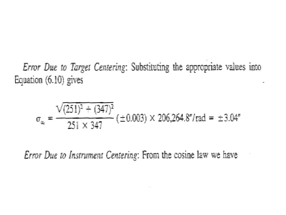
σσt = ± (D1) (D2) σt ρ D1D2 ρ= 206,264.8”/radian Assumes ability to center the target is independent of the particular direction. This makes σ1 = σ2 = σt
2 + (D2)2 σt ρ. D1D2. ρ= 206,264.8 /radian. Assumes ability to center the target is independent of the particular direction. This makes σ1 = σ2 = σt.")
26
TARGET CENTERING ERRORS

27
TARGET CENTERING ERRORS
If a hand-held range pole were used in this example with an estimated centering error of +/- 0.01’, the estimated error due to target centering would be almost 10”. This is why a range pole makes for a poor control point measuring tool.

28
INSTRUMENT CENTERING ERRORS
Set-up location vs. True Location Dependent on quality of instrument State of adjustment of optical plummet Skill of observer Can be compensating Error is maximized when the individual setup is on the angle bisector.

29
INSTRUMENT CENTERING ERRORS
Bisector angle error maximized at b and c.

30
INSTRUMENT CENTERING ERRORS

31
INSTRUMENT CENTERING ERRORS
σαi2 = ± D σi ρ D1D2 √2 ρ = 206,264.8”/radian

32
INSTRUMENT CENTERING ERRORS

33
EFFECTS OF LEVELING ERROR
If instrument is not level, then its vertical axis is not vertical and the horizontal circle is not horizontal Errors are most severe when backsight and or foresight is steeply inclined. Error tends to be random Random error- If the bubble of a theodolite were to remain off center by the same amount during the entire angle-measuring process at a station, the resulting error would be systematic. However, because an operator normally carefully monitors the bubble and attempts to keep it centered while turning angles, the amount and direction by which the instrument is out of level become random, and hence the resulting errors tend to be random.

34
EFFECTS OF LEVELING ERROR
σαl = ± fdμ tan (vb) 2 + fdμ tan (vf) 2 √ n
 2 + fdμ tan (vf) 2. √ n.")
35
EFFECTS OF LEVELING ERROR
σαl = ± fdμ tan (vb) 2 + fdμ tan (vf) 2 √ n Fd = the fractional division the instrument is off level Vb and vf = vertical angles to the BS and FS respectively n = the number of repetitions
 2 + fdμ tan (vf) 2. √ n. Fd = the fractional division the instrument is off level. Vb and vf = vertical angles to the BS and FS respectively. n = the number of repetitions.")
36
EFFECTS OF LEVELING ERROR
This error is generally small for traditional surveying when normal care in leveling the instrument is taken. Thus is can be ignored except for precise work.

44
POSSIBLE SOURCES OF ERRORS
TRAVERSING BY GPS POSSIBLE SOURCES OF ERRORS REFERENCE POSITION ERRORS ANTENNA POSITION ERRORS TIMING ERRORS SIGNAL PATH ERRORS HUMAN ERRORS COMPUTING ERRORS SATELLITE CONSTELLATION ERRORS NOISE CAUSING ERRORS REFERENCE POSITION-COORDINATE, MONUMENT STABILITY, CRUSTAL MOTION ANTENNA POSITION-EQUIPMENT SETUP, PHASE CENTER VARIATION AND OFFSETS SATELLITE POSITION-ORBIT EPHEMERIS ERRORS TIMING ERRORS-SATELLITE OR RECEIVER CLOCK ERRORS SIGNAL PATH ERRORS- ATMOSPHERIC DELAY AND REFRACTION, MULTIPATH HUMAN ERRORS-FIELD OR OFFICE BLUNDERS COMPUTING ERRORS-PROCESSING STATISTICAL MODELING ERRORS SATELLITE CONSTELLATION- VDOP & PDOP & # OF SATELLITES NOISE CAUSING-CELL PHONES, RADIOS, VEHICLES, POWER TRANSMISSION LINES, MICROWAVE SIGNALS

45
TOTAL STATION POSSIBLE SOURCES OF ERROR
COLLIMATION-TO ADJUST THE LINE OF SIGHT OR LENS AXIS OF AN OPTICAL INTRUMENT SO THAT IT IS IN ITS PROPER POSITION RELATIVE TO OTHER PARTS OF THE INSTRUMENT.

46
COLLIMATION MAIN MIRROR INSTRUMENT EYE PIECE

48
PARALLAX A change in the apparent position of an object with respect to the reference marks of an instrument which is due to imperfect adjustment of the instrument, to a change in the position of the observer, or both. Parallax occurs when the focal point of the eyepiece does not coincide with the plane of the cross hairs. Depending on the shape of each observer’s eyeball, the focal length may vary. This is also a major concern in the optical plummet. To check for parallax in the telescope, focus on some well-defined distant object. Slowly move the head back and forth, about an inch from the eyepiece, while watching the relationship of the object to the cross hairs. If the object appears to move, parallax exists. The optical plummet can be checked by rotating the knurled eyepiece until the cross hairs are the thickest and blackest, refocus and check for parallax.

49
HUMAN ERRORS Measuring the height of the instrument and reflector.
Setting up the instrument and reflector Push the tripod shoes firmly into the ground Place the legs in positions that will require minimum walking around the setup. Ensure the instrument is set properly over the point. Do not stamp on the tripod feet. Pressure should be parallel to each leg. Legs- In windy conditions, additional stability can be achieved if one leg is set downwind. On hillsides- one leg uphill and two legs downhill If the ground in soft or muddy, drive hubs in the ground to support the tripod legs.

50
HUMAN ERRORS Check the optical plummet after the instrument is set up and just before moving to another point. Recheck the instrument level If the instrument has moved, check the angle just measured. The bubble should remain within one graduation when the instrument is smoothly turned through one circle (if the instrument is shaded).
.")
51
ACCURACY OF A GPS SURVEY
ACCURACY DEPENDENT UPON MANY COMPLEX, INTERACTIVE FACTORS, INCLUDING OBSERVATION TECHNIQUE USED, e.g., static vs. kinematic, code vs. phase, etc. Amount and quality of data acquired GPS signal strength and continuity Ionosphere and troposphere conditions Station site stability, obstructions, and multipath

52
ACCURACY OF A GPS SURVEY
Satellite orbit used, e.g., predicted vs. precise orbits Satellite geometry, described by the dilution of precision (DOP) Network design, e.g., baseline length and orientation Processing methods used, e.g., double vs. triple differencing, etc.
 Network design, e.g., baseline length and orientation. Processing methods used, e.g., double vs. triple differencing, etc.")
53
OPERATIONAL PROCEDURES
IDENTIFY AND MINIMIZE ALL ERRORS BY REDUNDANCY, ANALYSIS, AND CAREFUL OPERATIONAL PROCEDURES, INCLUDING: REPETITION OF MEASUREMENTS UNDER INDEPENDENT CONDITIONS REDUNDANT TIES TO MULTIPLE, HIGH-ACCURACY CONTROL STATIONS GEODETIC GRADE INSTRUMENTATION, FIELD AND OFFICE PROCEDURES

54
OPERATIONAL PROCEDURES
ENSURE PROCESSING WITH THE MOST ACCURATE STATION COORDINATES, SATELLITE EPHEMERIDES, AND ATMOSPHERIC AND ANTENNA MODELS AVAILABLE. CAUTION: BE AWARE THAT THESE PROCEDURES CANNOT DISCLOSE ALL PROBLEMS.

Similar presentations


>")


