Download presentation
Presentation is loading. Please wait.

1
Programmable Logic Controllers PLC’s
التحكم المنطقى المبرمج

2
Overview Course Contents What is a PLC ? History
Overview of Technology PLC Configuration and Selection Programming PLC’s

3
Course Contents Introductions to PLC PLC Hardware Programming
Input / Output Processing Input Devices Output Devices Programming Internal Relays Timers Counters Projects

4
What is a PLC ?

5
What is a PLC ? A PLC works by looking at its inputs and depending on their state, and the user entered program, turns on/off outputs. A PLC can be thought of as: Industrial Computers with specially designed architecture in both their central units (the PLC itself) and their interfacing circuitry to field devices (input / output connections to the real world).
 and their interfacing circuitry to field devices (input / output connections to the real world).")
6
Commercial And Industrial Computers
Commercial Computer Industrial Computer

7
History 1/5 Early control systems consisted of huge control boards consisting of hundreds to thousands of electromechanical relays. An Engineer would design the system logic. Electricians would receive a schematic outline of logic then implement the logic with relays. |/| CR3 M1 PB1 LS1 SOL2 PB2 LS3 LS4

8
History 2/5 The schematic was commonly called “Ladder Schematic”
The Ladder displayed all switches, sensors, motors, valves, relays etc in the system. Problems: Long implementation time, Mechanical dependence, Any system logic design change required the power to the control board to be isolated stopping production

9
History 3/5 General Motors was among the first to recognize a need to replace the systems “wired control board” Hydromantic Division of GM specified the design criteria for the programmable controller in 1968. Goal – Eliminate the high cost associated with inflexible, Relay controlled systems.

10
History 4/5 New Controller Specifications: Solid State System
Computer Flexibility Operate in Industrial Environment (vibrations, heat, dust etc.) Capability of being reprogrammed Easily programmed and maintained by electricians and technicians.
 Capability of being reprogrammed. Easily programmed and maintained by electricians and technicians.")
11
History 5/5 In 1969 Gould Modicon developed the first PLC.
Strength – Programmed with Ladder Logic Initially called Programmable Controllers PC’s Now PLC’s, Programmable Logic Controllers PLC’s have evolved from simple on/off control to being able to communicate with other control systems, provide production reports, schedule production, diagnose machine and process faults.

12
Relay Logic vs. PLC & Ladder Logic
Programmable Logic Controller Inputs Outputs CR |/| CR3 M1 PB1 LS1 SOL2 PB2 LS3 LS4 X0 X1 Y0 | | | | ( ) X2 X3 M0 | | | | ( ) X4 | | |/| M0 X5 Y1 | | ( )
 X2. X3. M0. | | | | ( ) X4. | | |/| M0. X5. Y1. | | ( )")
13
PLC Configuration RACK SHOE BOX (UNITARY) MICRO
 MICRO")
14
The Configuration of PLC
The configuration of PLC refers to the packaging of the components. Typical configurations are listed below from largest to smallest. Rack Type : A rack is often large (up to 18” by 30” by 10”) and these use a range of modules that use together to build up a system. Shoebox: A compact, all-in-one unit that has limited expansion capabilities. Lower cost and compactness make these ideal for small applications. Micro: These units can be as small as a deck of cards. They tend to have fixed quantities of I/O and limited abilities, but costs will be lowest. 1
 and these use a range of modules that use together to build up a system. Shoebox: A compact, all-in-one unit that has limited expansion capabilities. Lower cost and compactness make these ideal for small applications. Micro: These units can be as small as a deck of cards. They tend to have fixed quantities of I/O and limited abilities, but costs will be lowest. 1.")
15
Most Basic of PLC Systems
In the most basic of PLC systems, a self contained (shoe box) PLC has 2 terminal blocks, one for Inputs and one for Outputs Today, most PLC’s in this category are know as Micrologix. Typically they provide front panel LED status indication of I/O and Processor states Inputs Outputs Programmable Controller CR
 PLC has 2 terminal blocks, one for Inputs and one for Outputs. Today, most PLC’s in this category are know as Micrologix. Typically they provide front panel LED status indication of I/O and Processor states. Inputs. Outputs. Programmable Controller. CR.")
16
Modular Chassis Based PLC’s
The vast majority of PLC’s installed today are modular chassis based systems consisting of: Processor Module (CPU) Input & Output Modules Chassis Power Supply
 Input & Output Modules. Chassis. Power Supply.")
17
Modular Chassis Based PLC’s

18
Sizing of PLC Micro PLCs: I/O up to 32 points
Small PLC: I/O up to 128 points Medium PLC: I/O up to 1024 points Large PLC: I/O up to 4096 points Very Large: I/O up to 8192 points 1

19
Overview of Technology

20
Basic PLC Schema CPU Power Supply Memory Input Module Output Module
Programming devices Communications Expansion Connections

21
CPU Module

22
CPU Module Cont’d The Central Processing Unit (CPU) Module is the brain of the PLC. CPU architecture may differ from one manufacturer to another, but in general, most CPUs follow this typical three-component organization (Processor, Memory, Power Supply) The term CPU is often used interchangeably with the word Processor; however, the CPU encompasses all of the necessary elements that form the intelligence of the system—the processor plus the memory system and power supply 1
 The term CPU is often used interchangeably with the word Processor; however, the CPU encompasses all of the necessary elements that form the intelligence of the system—the processor plus the memory system and power supply. 1.")
23
PLC Operating Cycle PLC Program SCAN The basic function of a programmable controller is to read all of the field input devices and then execute the control program, which according to the logic programmed, will turn the field output devices ON or OFF. A PLC works by continually scanning a program

24
PLC Operating Cycle Cont’d.
START Housekeeping Input Scan Internal checks on memory, speed and operation. Service any communication requests, etc. The status of external inputs (terminal block voltage) is written to the Input image (“Input file”). Output Scan Program Scan The Output Image data is transferred to the external output circuits, turning the output devices ON or OFF. The job description of the PLC when it is the RUN mode Each ladder rung is scanned using the data in the Input file. The resulting status (Logic being solved) is written to the Output file (“Output Image”).
 is written to the Input image ( Input file ). Output Scan. Program Scan. The Output Image data is transferred to the external output circuits, turning the output devices ON or OFF. The job description of the PLC when it is the RUN mode. Each ladder rung is scanned using the data in the Input file. The resulting status (Logic being solved) is written to the Output file ( Output Image ).")
25
Scan Time The scan time is the total time the PLC takes to complete the program and I/O update scans

26
Scan Time Cont’d The program scan time generally depends on two factors: the amount of memory taken by the control program the type of instructions used in the program (which affects the time needed to execute the instructions) The time required to make a single scan can vary from a few tenths of a millisecond to 50 milliseconds.
 The time required to make a single scan can vary from a few tenths of a millisecond to 50 milliseconds.")
27
Power Supply The system power supply plays a major role in the total system operation. Its responsibility is not only to provide internal DC voltages to the system components (i.e., processor, memory, and input/output interfaces), but also to monitor and regulate the supplied voltages and warn the CPU if something is wrong. PLC power supplies require input from an AC power source; however, some PLCs will accept a DC power source. Most PLCs, however, require a 120 VAC or 220 VAC power source, while a few controllers will accept 24 VDC.
, but also to monitor and regulate the supplied voltages and warn the CPU if something is wrong. PLC power supplies require input from an AC power source; however, some PLCs will accept a DC power source. Most PLCs, however, require a 120 VAC or 220 VAC power source, while a few controllers will accept 24 VDC.")
28
Memory The memory includes pre-programmed ROM memory containing the PLC’s operating system, driver programs and application programs and the RAM memory. PLC manufacturer offer various types of retentive memory to save user-programs and data while power is removed, so that the PLC can resume execution of the user-written control program as soon as power is restored. 1

29
Memory cont’d Many PLCs also offer removable memory modules, which are plugged into the CPU module. Memory can be classified into two basic categories: volatile and non-volatile. - Volatile memory is that which loses state (the stored information) when power is removed. - Non-volatile memory, on the other hand, maintains the information in memory even if the power is interrupted.
 when power is removed. - Non-volatile memory, on the other hand, maintains the information in memory even if the power is interrupted.")
30
Memory cont’d Some types of memory used in a PLC include:
ROM (Read-Only Memory) This memory is permanent and cannot be erased. It is often used for storing the operating system for the PLC.
 This memory is permanent and cannot be erased. It is often used for storing the operating system for the PLC.")
31
Memory cont’d RAM (Random Access Memory)
This memory is fast, but it will lose its contents when power is lost, this is known as volatile memory. Every PLC uses this memory for the central CPU when running the PLC. For the most part, today’s programmable controllers use RAM with battery support for application memory. Random-access memory provides an excellent means for easily creating and altering a program, as well as allowing data entry

32
Memory cont’d EEPROM (Electrically Erasable Programmable Read-Only Memory) This memory can store programs like ROM. It can be programmed and erased using a voltage, so it is becoming more popular than EPROMs. Several of today’s small and medium-sized controllers use EEPROM as the only memory within the system. It provides permanent storage for the program and can be easily changed with the use of a programming device (e.g., a PC) or a manual programming unit.
 or a manual programming unit.")
33
Application Memory The application memory stores programmed instructions and any data the processor will use to perform its control functions. The controller stores all data in the data table section of the application memory, while it stores programmed instructions in the user program section.

34
Application Memory Cont’d
The input table is an array of bits that stores the status of digital inputs connected to the PLC’s input interface. The maximum number of input table bits is equal to the maximum number of field inputs that can be connected to the PLC

35
Application Memory Cont’d
The output table is an array of bits that controls the status of digital output devices that are connected to the PLC’s output interface. The maximum number of bits available in the output table equals the maximum number of output field devices that can interface with the PLC.

36
I/O Modules Input and output (I/O) modules connect the PLC to sensors and actuators. Provide isolation for the low-voltage, low-current signals that the PLC uses internally from the higher-power electrical circuits required by most sensors and actuators. Wide range of I/O modules available including: digital (logical) I/O modules and analog (continuous) I/O modules. 1
 I/O modules and analog (continuous) I/O modules. 1.")
37
Inputs Modules Inputs come from sensors that translate physical or chemical phenomena into electrical signals. The simplest form of inputs are digital/discrete in AC/DC. In smaller PLCs the inputs are normally built in and are specified when purchasing the PLC. For larger PLCs the inputs are purchased as modules, or cards, with 8,16, 32, 64, 96 inputs of the same type on each card. 1

38
Inputs Modules Cont’d The list below shows typical ranges for input voltages. 5 Volts DC TTL level 24 Volts AC/DC 48 Volts AC/DC 110 Volts AC/DC 220 Volts AC/DC 1

39
An AC/DC Input Block diagram Circuit

40
SOURCING vs. SINKING Sensor With PNP Output Sensor With NPN Output

41
Sinking DC Inputs When a PLC input card does not have a common but it has a V+ instead, it can be used for NPN sensors. In this case the current will flow out of the card (sourcing) and we must switch it to ground.
 and we must switch it to ground.")
42
Sourcing DC Inputs When we have a PLC input card that has a common then we can use PNP sensors. In this case the current will flow into the card and then out the common to the power supply.

43
Rules Sourcing field devices must be connected to sinking I/O cards
Sinking field devices must be connected to sourcing I/O cards

44
Device connections for DC input module for an AC input module 1

45
Input Devices Pushbuttons Selector Switches Limit Switches
Level Switches Photoelectric Sensors Proximity Sensors Motor Starter Contacts Relay Contacts Thumbwheel Switches Field input devices provide an electrical signal based on a condition ON, OFF etc.. The design of the inputs determines the type of electrical signal that can be used. Different applications, and regions may use different voltages. Larger rack mount PLC’s typically support a wider range of input voltages TTL (5Vdc), 12Vdc, 24Vdc/VAC, 48Vdc, 72Vdc, 120Vac, 220Vac etc... 3
, 12Vdc, 24Vdc/VAC, 48Vdc, 72Vdc, 120Vac, 220Vac etc")
46
Outputs Modules Output modules rarely supply any power, but instead act as switches. External power supplies are connected to the output card and the card will switch the power on or off for each output. A common choice when purchasing output cards is relays, transistors or triacs. Relay are the most flexible output devices. They are capable of switching both AC and DC outputs. But, they are slower, cost more, and they will wear out after millions of cycles. 1

47
An AC Output Circuit The AC switch
is normally protected by an RC snubber and/or a metal oxide varistor (MOV), which limits the peak voltage to some value below the maximum rating. Snubber and MOV circuits also prevent electrical noise from affecting the circuit operation.
, which limits the peak voltage to some value below the maximum rating. Snubber and MOV circuits also prevent electrical noise from affecting the. circuit operation.")
48
DC Output As in DC inputs, DC output modules may have either sinking or sourcing configurations. If a module has a sinking configuration, current flows from the load into the module’s terminal, switching the negative (return or common) voltage to the load. The positive current flows from the load to the common via the module’s power transistor. In a sourcing module configuration, current flows from the module into the load, switching the positive voltage to the load
 voltage to the load. The positive current flows from the load to the common via the module’s power transistor. In a sourcing module configuration, current flows from the module into the load, switching the positive voltage to the load.")
49
An Example of a 24Vdc Output Card With a Voltage Input (Sourcing)
")
50
An Example of a 24Vdc Output Card (Sinking)
")
51
Relays When using relay outputs it is possible to have each output isolated from the next. A relay output card could have AC and DC outputs beside each other. Relay outputs are usually used to control up to 2 amps or when a very low resistance is required. Transistor outputs are open collector common emitter or emitter follower 1

52
An Example of a Relay Output Card
1

53
Outputs Typical output voltages are listed below, 24 Volts AC/DC
5 Volts DC TTL level 24 Volts AC/DC 48 Volts AC/DC 110 Volts AC/DC 220 Volts AC/DC WARNING: Always check rated voltages and currents for PLCs and never exceed. 1

54
Output Devices Valves Motor Starters Solenoids Control Relays Alarms
Lights Fans Horns Field output devices are controlled by electricity being switched by the PLC. ON, OFF etc.. PLC’s “Switch” electricity, they do not “supply” electricity The design of the outputs determines the type of electrical “Load” that can be used. Different applications may require specialized output designs. Voltage/Current issues include Higher current - relays Longer life cycle - solid state (Triacs for AC, MOSFET for DC) Triacs 120Vac applications 1/2 amp maximum load MOSFET 24Vdc applications 1 amp maximum load Isolation issues can be crucial for an application. Typically the more isolation provided between output points the better. (The more individual commons the better) This provides customers greater flexibility in wiring and controlling different loads with the same PLC. 4
 Triacs 120Vac applications 1/2 amp maximum load. MOSFET 24Vdc applications 1 amp maximum load. Isolation issues can be crucial for an application. Typically the more isolation provided between output points the better. (The more individual commons the better) This provides customers greater flexibility in wiring and controlling different loads with the same PLC. 4.")
55
Programmable controller I/O connection diagram

56
Analogue Cards Typical Analogue Input signals are:
Flow sensors Humidity sensors Pressure sensors Temperature sensors Vibration Analogue Output signals control: Analogue Valves Variable Speed Drives Typical Analogue Signal Levels 4 - 20mA 1 - 5 Vdc Vdc -10 – 10Vdc 1

57
Analogue Inputs/Outputs
Analogue input cards convert continuous signals via a A/D converter into discrete values for the PLC Analogue output cards convert digital values in then PLC to continuous signals via a D/A converter. Resolution can be important in choosing an applicable card

58
Programming Devices PLC manufacturers have always maintained an easy human interface for program entry. This means that users do not have to spend much time learning how to enter a program, but rather they can spend their time programming and solving the control problem. Most PLCs are programmed using very similar instructions. The only difference may be the mechanics associated with entering the program into the PLC, which may vary from manufacturer to manufacturer The two basic types of programming devices are: Mini-programmers personal computers

59
Mini-Programmers

60
Mini-Programmers Cont’d
Mini-programmers, also known as handheld or manual programmers, are an inexpensive and portable way to program small PLCs (up to 128 I/O). Mini-programmers can also be useful tools for starting up, changing, and monitoring the control logic Some mini-programmers offer removable memory cards or modules, which store a complete program that can be reloaded at any time into any member of the PLC family Most mini-programmers are designed so that they are compatible with two or more controllers in a product family
. Mini-programmers can also be useful tools for starting up, changing, and monitoring the control logic. Some mini-programmers offer removable memory cards or modules, which store a complete program that can be reloaded at any time into any member of the PLC family. Most mini-programmers are designed so that they are compatible with two or more controllers in a product family.")
61
Personal Computer Common usage of the personal computer (PC) in our daily lives has led to the practical elimination of dedicated PLC programming devices. Due to the personal computer’s general-purpose architecture and standard operating system, most PLC manufacturers provide the necessary PC software to implement ladder program entry, editing, documentation, and real-time monitoring of the PLC’s control program.
 in our daily lives has led to the practical elimination of dedicated PLC programming devices. Due to the personal computer’s general-purpose architecture and standard operating system, most PLC manufacturers provide the necessary PC software to implement ladder program entry, editing, documentation, and real-time monitoring of the PLC’s control program.")
62
Selecting a PLC Number of logical inputs and outputs Memory
Number of special I/O modules Expansion Capabilities Scan Time Communication Software Support Dollars 1

63
Example of PLC Specifications
1

64
Manufactures Major Brands OMRON Allen Bradley
Schneider (Modicon, Telemecanique, Square D) GE Fanuc Siemens Automation Direct (Koyo) Toshiba Mitsubishi Hitachi
 GE Fanuc. Siemens. Automation Direct (Koyo) Toshiba. Mitsubishi. Hitachi.")
65
Programming PLC’s The purpose of a PLC Program is to control the state of PLC outputs based on the current condition of PLC Inputs A program is a connected series of instructions written in a language that the PLC can understand. There are three forms of program format: instruction: a word/mnemonic entry system Ladder: a graphical program construction method using a relay logic symbols SFC (Sequential Function Chart) :a flow chart style of STL (STep Ladder) program entry
 :a flow chart style of STL (STep Ladder) program entry.")
66
Programming PLC’s Cont’d
Not all programming tools can work in all programming forms. Generally hand held programming panels only work with instruction format while most graphic programming tools will work with both instruction and ladder format. Specialist programming software will also allow SFC style programming.

67
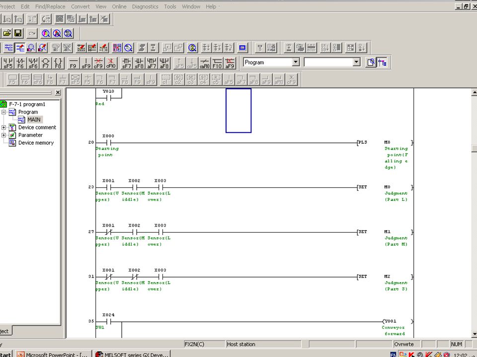
Programming PLC’s Cont’d

69
Ladder Logic Concepts | | ( ) | | |/| | | | | |/| | | |/| | | | | |/|
Read / Conditional Instructions Write / Control Instructions | | Start (Rung #1) ( ) | | |/| | | | | |/| | | |/| | | | | |/| ( ) End (Rung #5)
 ( ) | | |/| | | | | |/| | | |/| | | | | |/| ( ) End (Rung #5)")
70
Ladder Logic Concepts The vertical line of the diagram represent the power rails Each rung on the ladder defines one operation in the control process Ladder diagram is read from left to right and from top to bottom Each rung must start with an input or inputs and must end with at least one output One device can appear in more than one rung of ladder Inputs and outputs are all identified by their address the notation used depending on the plc manufacture

71
Ladder Logic Concepts

72
Advantages Of PLC The advantages they offer are:
Cost effective for controlling complex systems Flexible and can be reapplied to control other systems quickly and easily Trouble shooting aids make programming easier and reduce downtime Reliable components, ensure operation for years Variety of I/O interfaces

73
Advantages Of PLC Cont’d
Small size Growing with technology, faster scan times, capability etc Quick I/O disconnects that aids in field servicing Software Timers/Counter, Relays Clean failure mode On-line programming Availability of replacement parts

74
Input Devices The most common class of input interfaces is digital (or discrete). Discrete input interfaces connect digital field input devices (those that send noncontinuous, fixed-variable signals) to input modules of programmable controller. The discrete, noncontinuous characteristic of digital input interfaces limits them to sensing signals that have only two states (ON/OFF, OPEN/CLOSED, TRUE/FALSE). To an input interface circuit, discrete input devices are essentially switches that are either open or closed, signifying either 1 (ON) or 0 (OFF).
 to input modules of programmable controller. The discrete, noncontinuous characteristic of digital input interfaces limits them to sensing signals that have only two states (ON/OFF, OPEN/CLOSED, TRUE/FALSE). To an input interface circuit, discrete input devices are essentially switches that are either open or closed, signifying either 1 (ON) or 0 (OFF).")
75
Input Devices Cont’d Analog signals have an infinite number of states. Temperature, for example, is an analog signal because it continuously changes by infinitesimal amounts. Consequently, a change from 70°F to 71°F is not just one change of 1°F, but rather an infinite number of smaller changes of a fraction of a degree. Analog input modules digitize analog input signals, thereby bringing analog information into the PLC

76
Mechanical Switch The mechanical switch generates an on/off signal or signals as a result of some mechanical input causing the switch to open or close Switches are available with normally open (NO) or normally close (NC) NO contact has its contact open in the absence of a mechanical input and the mechanical input is used to close the switch NC contact has its contact closed in the absence of a mechanical input and the mechanical input is used to open the switch
 or normally close (NC) NO contact has its contact open in the absence of a mechanical input and the mechanical input is used to close the switch. NC contact has its contact closed in the absence of a mechanical input and the mechanical input is used to open the switch.")
77
Mechanical Switch cont’d
On/Off switch (Toggle switch) Limit switch
 Limit switch.")
78
Mechanical Switch cont’d
Limit switch

79
Proximity switches Proximity sensors are discrete sensors that sense when an object has come near to the sensor face. There are four fundamental types of proximity sensors the inductive proximity sensor, the capacitive proximity sensor, the ultrasonic proximity sensor, and the optical proximity sensor.

80
Inductive Proximity Sensor
Inductive proximity sensors operate on the principle that the inductance of a coil vary as a metallic (or conductive) object is passed near to it. Because of this operating principle, inductive proximity sensors are only used for sensing metal objects. They will not work with non-metallic materials. Small diameter sensors (approximately ¼” in diameter) have typical sensing ranges in the area of 1mm, while large diameter sensors (approximately 3" in diameter) have sensing ranges in the order of 50mm or more
 object is passed near to it. Because of this operating principle, inductive proximity sensors are only used for sensing metal objects. They will not work with non-metallic materials. Small diameter sensors (approximately ¼ in diameter) have typical sensing ranges in the area of 1mm, while large diameter sensors (approximately 3 in diameter) have sensing ranges in the order of 50mm or more.")
81
Inductive Proximity Sensor cont’d

82
Capacitive Proximity Sensor
Capacitive proximity sensors are available in shapes and sizes similar to the inductive proximity sensor capacitive proximity sensors will sense both metallic and non-metallic objects. The principle of operation of the sensor is that an internal oscillator will not oscillate until a target is moved close to the sensor face. The target varies the capacitance of a capacitor in the face of the sensor that is part of the oscillator circuit.

83
The Ultrasonic Proximity Sensor
An ultrasonic “ping” is sent from the face of the sensor. If a target is located in front of the sensor and is within range, the ping will be reflected by the target and returned to the sensor. When an echo is returned, the sensor detects that a target is present, and by measuring the time delay between the transmitted ping and the returned echo, the sensor can calculate the distance between the sensor and the target.

84
The Ultrasonic Proximity Sensor

85
Optical Proximity Sensor
Optical sensors are an extremely popular method of providing discrete-output sensing of objects. Since the sensing method uses light, it is capable of sensing any objects that are opaque. They operate over long distances (as opposed to inductive or capacitive proximity sensors), will sense in a vacuum (as opposed to ultrasonic sensors), and can sense any type of material no matter whether it is metallic or nonmetalic
, will sense in a vacuum (as opposed to ultrasonic sensors), and can sense any type of material no matter whether it is metallic or nonmetalic.")
86
Transmissive Type

87
Reflective Type

88
Benefits The benefits achieved with programmable controllers will grow with the individual using them: “The more you learn about PLC’s, the more you will be able to solve other control problems.”

89
Thank you…. Questions ?

Similar presentations


 4/19/2017 A digitally operating electronic apparatus which uses a programming.>")


 AND AUTOMATION>")