Download presentation
Presentation is loading. Please wait.

1
Instructor: Dr. Lynn Ziegler
Assembly & Machine Languages CSCI130 Instructor: Dr. Lynn Ziegler

2
Layered Architecture LAYER Order High-order P.L.: Visual Basic 1
System SW: O.S. 3 Data Representation 5

3
Higher-level Programming Languages
(3GL) High-level languages are in the middle Use English-like phrases and mathematical notation x = x+1; A limited vocabulary with precise meaning Make us think at a higher-level of abstraction No attention to technical and hardware details Like O.S. Much larger instruction set for programmers Multiplication Don’t worry about what circuits are available 3
 High-level languages are in the middle. Use English-like phrases and mathematical notation. x = x+1; A limited vocabulary with precise meaning. Make us think at a higher-level of abstraction. No attention to technical and hardware details. Like O.S. Much larger instruction set for programmers. Multiplication. Don’t worry about what circuits are available. 3.")
4
Higher-level Programming Languages (PLs)
(1GL) Machine language programming limited set of instructions binary numbers: opcodes, absolute memory addresses and data Memory addresses (2GL) Assembly language English mnemonics for binary opcodes Decimal data Labels for memory addresses and variables limited instruction set Use human languages to program Large vocabulary (space and time to search) … opcode lookup 500,000 words - 1,000,000 words (including scientific words) Synonyms Context
 Machine language programming. limited set of instructions. binary numbers: opcodes, absolute memory addresses and data. Memory addresses. (2GL) Assembly language. English mnemonics for binary opcodes. Decimal data. Labels for memory addresses and variables. limited instruction set. Use human languages to program. Large vocabulary (space and time to search) … opcode lookup. 500,000 words - 1,000,000 words (including scientific words) Synonyms. Context.")
5
CPU - Connects to main memory (MM) thru a bus - Bus = bundle of wires
- Transfers data between CPU and memory - Width of bus determines speed - e.g. 32-bit bus (Higher faster) - Where is data stored when copied to CPU?
 - Where is data stored when copied to CPU")
6
CPU Divided into CU and ALU CU (Control Unit)
Orchestra organizer Oversees transfer of data between MM and CPU Accesses info in ROM (e.g. during reboot) Has a bunch of memory registers ALU (Arithmetic Logic Unit) Contains circuits to do computations Built for each basic/hardwired operation (+,-, x, /, =,>,<, NOT) Includes a special register accumulator AC to hold results
 Has a bunch of memory registers. ALU (Arithmetic Logic Unit) Contains circuits to do computations. Built for each basic/hardwired operation (+,-, x, /, =,>,<, NOT) Includes a special register accumulator AC to hold results.")
7
The History of Computing
Computers are made up of units called gates and storage units. Gates are used to process data while storage units are used to store data. Vacuum tubes were used for both. ENIAC (February 14, 1946) weighed over 30 tons, and consumed 200 kilowatts of electrical power 7
 weighed over 30 tons, and consumed 200 kilowatts of electrical power. 7.")
8
An ALU in 1957 This was an arithmetic unit you sit back and admire. It was part of Honeywell's Datamatic 1000 computer. (Image courtesy of Honeywell, Inc.)
")
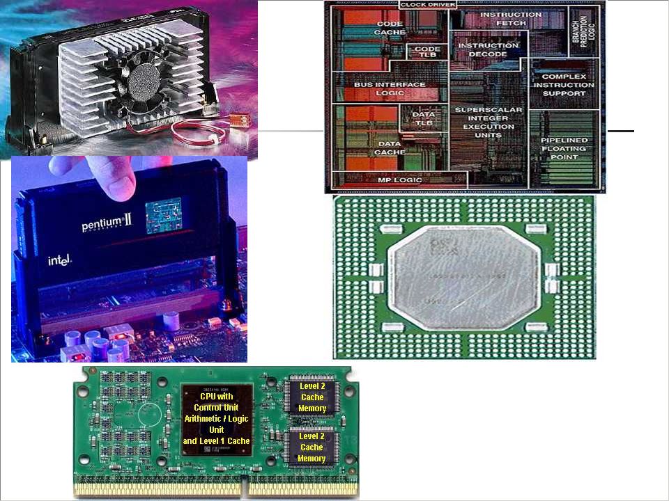
11
Modern CPUs

12
Programs & Algorithms Characteristics of an algorithm:
List of steps to complete a task Each step is PRECISELY defined and is suitable for the machine used Increase the value of X Jump! Add 5 to variable X The process terminates in a finite amount of time No infinite loops Written in an English-like language (Pseudocode) 12
 12.")
13
Programs & Algorithms Program: A formal representation of a method for performing some task Written in a programming language understood by a computer Detailed and very well-organized (computers just do what they are told) Follows an algorithm … method for fulfilling the task Plan to do something VS the actual performance
 Follows an algorithm … method for fulfilling the task. Plan to do something VS the actual performance.")
14
Combining Limited Instructions
Computing an answer to an equation: 5* – 7 Assume our computer can’t directly multiply, subtract, or raise to power Multiplication task: 1: Get 1st number, Number_1 2: Get 2nd number, Number_2 3: Answer = 0 4: Add Number_1 to Answer 5: Subtract 1 from Number_2 6: if Number_2>0, go to step 4 7: Stop Shows you in bold what functionality is needed to accomplish the task at hand 14

15
Assembly Language Machine code consists of the
binary instructions, data & addresses can directly be executed by the CPU We as humans are not good in working with sequences of 1’s and 0’s We prefer to use an English-like style (English mnemonics and decimal numbers) This is called the assembly language It has 1-to-1 correspondence to machine code one instruction for every 3-bit Opcode and decimal numbers for addresses and data Slight other changes
 This is called the assembly language. It has 1-to-1 correspondence to machine code. one instruction for every 3-bit Opcode and decimal numbers for addresses and data. Slight other changes.")
16
Assembly Language Additional problems addressed:
Most commands like LOAD, STOR, JUMP and ADD require memory addresses How do we know which address in memory is free to use? We also assumed that PC will contain 0 initially Our program will be loaded to first memory location…is this always true? What if we have multiple executing programs on the same machine? Which will get the 0 address then?

17
Assembly Language In reality, when we program, we don’t concern ourselves with such low level details This is handled by the operating system. From now on, we use variables/labels instead of addresses and totally forget about memory ADD Counter which must initialized

18
clock MHz (~3.0 GHz)
")
19
Assembly Language of a Computer
Instruction Description HALT Stop program execution JUMP loc Go to location loc to continue program execution (unconditional) JZER loc Go to location loc to continue program execution but only if AC=0 (i.e. if zflag=1) (conditional) JPOS loc Go to location loc to continue program execution but only if AC>0 (i.e. if pflag=1) (conditional) LOAD loc Copy contents of location loc into AC (zflag, pflag might be affected) STOR loc Copy contents of AC into location loc ADD loc Add contents of location loc to AC (zflag, pflag might be affected) SUB loc Subtract contents of location loc from AC (zflag, pflag might be affected) READ Put user’s input inside AC (zflag, pflag might be affected) WRITE Output contents of AC to user – e.g. on screen 19
 JZER loc. Go to location loc to continue program execution but only if AC=0 (i.e. if zflag=1) (conditional) JPOS loc. Go to location loc to continue program execution but only if AC>0 (i.e. if pflag=1) (conditional) LOAD loc. Copy contents of location loc into AC (zflag, pflag might be affected) STOR loc. Copy contents of AC into location loc. ADD loc. Add contents of location loc to AC (zflag, pflag might be affected) SUB loc. Subtract contents of location loc from AC (zflag, pflag might be affected) READ. Put user’s input inside AC (zflag, pflag might be affected) WRITE. Output contents of AC to user – e.g. on screen. 19.")
20
Simple VB-like program 1
Private Sub cmdSimple () Dim X As Integer X = inputbox(…) Msgbox x End Sub READ STOR X LOAD X WRITE HALT X: 0
 Dim X As Integer. X = inputbox(…) Msgbox x. End Sub. READ. STOR X. LOAD X. WRITE. HALT. X: 0.")
21
Simple VB-like program 2
Private Sub cmdSimple () Dim X As Integer X = inputbox(…) If X>0 then Msgbox x End If End Sub
 Dim X As Integer. X = inputbox(…) If X>0 then. Msgbox x. End If. End Sub.")
22
Assembly Version for program 2
READ STOR X LOAD X JPOS Disp HALT Disp: WRITE X: 0

23
Simple VB-like program 3
Private Sub cmdSimple () Dim X As Integer Dim Y As Integer Y = 0 X = inputbox(…) If X>0 then Msgbox x Else Msgbox y End If End Sub
 Dim X As Integer. Dim Y As Integer. Y = 0. X = inputbox(…) If X>0 then. Msgbox x. Else. Msgbox y. End If. End Sub.")
24
Assembly Version for program 3
READ STOR X LOAD X JPOS Disp LOAD Y WRITE HALT Disp: WRITE HALT X: 0 Y: 0

25
VB-like program 4 Private Sub cmdSimple () Else End Sub
Dim X As Integer Dim Y As Integer Dim Z As Integer X = inputbox(…) Y = inputbox(…) Z = 0 If X>Y then Msgbox X ElseIf X=Y then Msgbox Z Else Msgbox Y End If End Sub
 Y = inputbox(…) Z = 0. If X>Y then. Msgbox X. ElseIf X=Y then. Msgbox Z. Else. Msgbox Y. End If. End Sub.")
26
Assembly Version for program 4
READ STOR X STOR Y LOAD X SUB Y JPOS MaxX JZER Equal LOAD Y WRITE HALT MaxX: LOAD X WRITE HALT Equal: LOAD Z X: 0 Y: 0 Z: 0

27
VB-like program 5 Msgbox Sum Private Sub cmdSimple () End Sub
Dim Sum As Integer Dim N As Integer N = inputbox(…) Do Sum = Sum + N N = N -1 Loop While N>0 Msgbox Sum End Sub
 Do. Sum = Sum + N. N = N -1. Loop While N>0. Msgbox Sum. End Sub.")
28
Assembly Version for program 5
READ STOR N Loop: LOAD Sum ADD N STOR Sum LOAD N SUB One JPos Loop LOAD Sum WRITE HALT Sum:0 N: 0 One:1

29
VB-like program 6 Msgbox Sum Private Sub cmdSimple () End Sub
Dim Sum As Integer Dim N1 As Integer Dim N2 As Integer N1 = inputbox(…) N2 = inputbox(…) Do Sum = Sum + N2 N2 = N2 -1 Loop While N2>=N1 Msgbox Sum End Sub
 N2 = inputbox(…) Do. Sum = Sum + N2. N2 = N2 -1. Loop While N2>=N1. Msgbox Sum. End Sub.")
30
Assembly Version for program 6
READ STOR N1 STOR N2 Loop: LOAD Sum ADD N2 STOR Sum LOAD N2 SUB One SUB N1 JPOS Loop JZER Loop LOAD Sum WRITE HALT Sum:0 N1: 0 N2: 0 One:1

31
VB-like program 6 VB-like: Dim Sum As Integer Dim N As Integer
Program to print a 1 if an input number is even (multiple of 2) and 0 otherwise Try it out in SimHymn: Applications.htm VB-like: Dim Sum As Integer Dim N As Integer N = InputBox(…) Do N = N - 2 Loop While N > 0 VB-like: If N = 0 Then MsgBox 1 Else MsgBox 0 End If Branch example 31
 and 0 otherwise. Try it out in SimHymn: Applications.htm. VB-like: Dim Sum As Integer. Dim N As Integer. N = InputBox(…) Do. N = N - 2. Loop While N > 0. VB-like: If N = 0 Then. MsgBox 1. Else. MsgBox 0. End If. Branch example. 31.")
32
Dec: 2 N: 0 One: 1 Zero: 0 READ STOR N LOOP: LOAD N SUB Dec STOR N
JPOS Loop JZER Even LOAD Zero WRITE HALT Even: LOAD One Dec: 2 N: 0 One: 1 Zero: 0

33
A Simple 8-bit Computer Use a simplified version of real computers to understand machine language programs 32 8-bit main memory registers 5 bits (25 registers) to represent an address 00000 to 11111 PC holds memory addresses 5-bit PC For simplicity, assume only positive and negative integers (2’s complement notation) 8-bit AC
 to represent an address to PC holds memory addresses 5-bit PC. For simplicity, assume only positive and negative integers (2’s complement notation) 8-bit AC.")
34
clock MHz (~3.0 GHz)
")
35
A Simple 8-bit Computer Two 1-bit flags
zflag: 1 if AC zero, 0 otherwise pflag: 1 is AC is positive, 0 otherwise ALU supports the following basic operations Addition, subtraction, if AC=0, if AC>0 8 instructions (next slide) 3 bits (8 instructions) 000 to 111 8 bits per memory location rest 5 bits of the instruction contain the address of the input data to the instruction III AAAAA 8-bit IR Memory holds 8-bit data or instructions
 3 bits (8 instructions) 000 to bits per memory location rest 5 bits of the instruction contain the address of the input data to the instruction. III AAAAA. 8-bit IR. Memory holds 8-bit data or instructions.")
36
The Machine Language Instruction set depending on CPU
Hardwired Binary code for each instruction (Opcode) Different CPUs might have different operations for which circuits exit in the ALU Programs can only use those opcodes The set of all opcodes (i.e. instructions) together is known as the machine language
 Different CPUs might have different operations for which circuits exit in the ALU. Programs can only use those opcodes. The set of all opcodes (i.e. instructions) together is known as the machine language.")
37
Assembly Language Computers can only understand machine code
Programs written in assembly must be translated to machine code to be executable by CPU The assembler is responsible for that Stored in memory and executed before any assembly program can be executed (english-like) assembly source code (binary) machine code Does a lookup for each word (Opcodes) Other things (find empty memory locations for my variables) The result is called object code
 assembly source code (binary) machine code. Does a lookup for each word (Opcodes) Other things (find empty memory locations for my variables) The result is called object code.")
38
Machine Language of a Computer
Instruction Opcode Address Description HALT: 000xxxxx 000 (i.e. 0) NOT USED Stop program execution (Halt does not require an address) JUMP: 001xxxxx 001 (i.e. 1) xxxxx Place address in PC (unconditional) JZER: 010xxxxx 010 (i.e. 2) Place address in PC only of AC=0 (i.e. if zflag=1) (conditional) JPOS: 011xxxxx 011 (i.e. 3) Place address in PC only of AC>0 (i.e. if pflag=1) (conditional) LOAD: 100xxxxx 100 (i.e. 4) Copy contents of address into AC (zflag, pflag might be affected) STOR: 101xxxxx 101 (i.e. 5) Copy contents of AC into address ADD: 110xxxxx 110 (i.e. 6) Add contents of address to AC (zflag, pflag might be affected) SUB: 111xxxxx 111 (i.e. 7) Subtract contents of address from AC (zflag, pflag might be affected)
 NOT USED. Stop program execution (Halt does not require an address) JUMP: 001xxxxx. 001 (i.e. 1) xxxxx. Place address in PC (unconditional) JZER: 010xxxxx. 010 (i.e. 2) Place address in PC only of AC=0 (i.e. if zflag=1) (conditional) JPOS: 011xxxxx. 011 (i.e. 3) Place address in PC only of AC>0 (i.e. if pflag=1) (conditional) LOAD: 100xxxxx. 100 (i.e. 4) Copy contents of address into AC (zflag, pflag might be affected) STOR: 101xxxxx. 101 (i.e. 5) Copy contents of AC into address. ADD: 110xxxxx. 110 (i.e. 6) Add contents of address to AC (zflag, pflag might be affected) SUB: 111xxxxx. 111 (i.e. 7) Subtract contents of address from AC (zflag, pflag might be affected)")
39
A Simple 8-bit Computer Input/Output (from user perspective)
LOAD 30: register 30 in memory is designated as an input cell A LOAD with address 30 causes machine to access an input device The user is asked to provide an input (input box) Program waits/pauses meanwhile The input is saved in address 30 and loaded to AC STOR 31: register 31 in memory is designated as an output cell The contents of AC is saved in address 31 Machine also copies data to output device User sees the output on his/her screen (message box)
 Program waits/pauses meanwhile. The input is saved in address 30 and loaded to AC. STOR 31: register 31 in memory is designated as an output cell. The contents of AC is saved in address 31. Machine also copies data to output device. User sees the output on his/her screen (message box)")
40
VB-like program 6 Msgbox Sum Private Sub cmdSimple () End Sub
Dim Sum As Integer Dim N1 As Integer Dim N2 As Integer N1 = inputbox(…) N2 = inputbox(…) Do Sum = Sum + N2 N2 = N2 -1 Loop While N2>=N1 Msgbox Sum End Sub
 N2 = inputbox(…) Do. Sum = Sum + N2. N2 = N2 -1. Loop While N2>=N1. Msgbox Sum. End Sub.")
41
Assembly Version for program 6
READ STOR N1 STOR N2 Loop: LOAD Sum ADD N2 STOR Sum LOAD N2 SUB One SUB N1 JPOS Loop JZER Loop LOAD Sum WRITE HALT Sum:0 N1: 0 N2: 0 One:1

42
Machine-like Version for program 6
0: LOAD 30 ( ) 1: STOR 17 ( ) 2: LOAD 30 ( ) 3: STOR 18 ( ) 4: LOAD 16 ( ) 5: ADD 18 ( ) 6: STOR 16 ( ) 7: LOAD 16 ( ) 8: SUB 19 ( ) 9: STOR 16 ( ) 10: SUB 17 ( ) 11: JPOS 4 ( ) 12: JZER 4 ( ) 13: LOAD 16 ( ) 14: STOR 31 ( ) 15: HALT ( ) 16: 0 ( ) 17: 0 ( ) 18: 0 ( ) 19: 1 ( )
 1: STOR 17 ( ) 2: LOAD 30 ( ) 3: STOR 18 ( ) 4: LOAD 16 ( ) 5: ADD 18 ( ) 6: STOR 16 ( ) 7: LOAD 16 ( ) 8: SUB 19 ( ) 9: STOR 16 ( ) 10: SUB 17 ( ) 11: JPOS 4 ( ) 12: JZER 4 ( ) 13: LOAD 16 ( ) 14: STOR 31 ( ) 15: HALT ( ) 16: 0 ( ) 17: 0 ( ) 18: 0 ( ) 19: 1 ( )")
43
Von Neumann Machine Will see how hardwired operations are accomplished later one Comparison and addition Build up other operations/tasks using those basic/hardwired operations ones Programmed operations

44
Fetch-Execute Cycle Programs are made up of instructions
Fetch-Decode-Execute CU supervises the fetch-execute cycle Fetches one instruction from memory Decodes instruction Increments PC Executes instruction

45
Fetch-Execute Cycle To supervise the fetch-execute cycle, the CU has two registers PC (program counter) Contains the address of the next instruction in memory to fetch Initially points to first instruction of a program After fetching an instruction, it is incremented by one unless there is a jump to some other instruction IR (instruction register) Holds the current instruction Also has a timing clock Clock chip that generates a steady stream of electric pulses At every pulse, the CPU proceeds by one step Fetch, send data to ALU, etc … Higher frequency clocks result in faster computers MHz (~3.0 GHz)
 Holds the current instruction. Also has a timing clock. Clock chip that generates a steady stream of electric pulses. At every pulse, the CPU proceeds by one step. Fetch, send data to ALU, etc … Higher frequency clocks result in faster computers MHz (~3.0 GHz)")
46
… ... … ... Cycle PC IR AC - 1 – F 1 – D 1 – I 1 1 – E 2 – F 5 2 – D
- 1 – F (LOAD 30) 1 – D 1 – I 1 1 – E 5 (user input for N1) 2 – F (STOR 17) 5 2 – D 2 – I 2 2 – E … ... Cycle PC IR AC 5 – F 5 (ADD 18) 0 (sum) 5 – D 5 – I 6 5 – E 7 (0+ N2 which is 7) … ... 11 – F 11 (JPOS 4) 1 (N2-N2) 11 – D 1 11 – I 12 11 – E 4
 1 – D. 1 – I – E. 5 (user input for N1) 2 – F (STOR 17) 5. 2 – D. 2 – I – E. … ... Cycle. PC. IR. AC. 5 – F (ADD 18) 0 (sum) 5 – D. 5 – I – E. 7 (0+ N2 which is 7) … – F (JPOS 4) 1 (N2-N2) 11 – D – I – E. 4.")
Similar presentations


 Computer Architectures. 2 For temporary storage of information, the CPU contains cells, or registers, that are conceptually similar to main.>")


