Download presentation
Presentation is loading. Please wait.

1
29 CFR 1926.650-652 and Appendices A - F
Excavations 29 CFR and Appendices A - F

11
Program Outline The Regulation: An Overview General Requirements
Definitions Soil Mechanics and Soil Types Soil Testing Visual Site Evaluation Protective Systems Special Health & Safety Considerations

12
The Regulation Excavating is one of the most hazardous construction operations according to OSHA. Excavations are covered by 29 CFR and Appendices A – F. OSHA also offers guidance in the “Technical Manual”. The Physical Plant also has procedures written in March, 1998.

13
General Requirements Identification of soil types and utilities before digging Decision chart Daily inspections Soil classification Special safety and health considerations Protective systems

14
General Requirements Protective Systems
Required for excavations 5 feet or greater in depth.

15
Definitions

16
Competent Person Competent Person is an individual who is capable of identifying existing and predictable hazards or working conditions that are hazardous, unsanitary, or dangerous to employees.

17
Competent Person The designated competent person should have and be able to demonstrate the following: Training, experience, and knowledge of: - soil analysis; - use of protective systems; and - requirements of 29 CFR Part Subpart P ( and Appendices A-F).
.")
18
Competent Person The designated competent person should have and be able to demonstrate the following: Ability to detect: - conditions that could result in cave-ins; - failures in protective systems; - hazardous atmospheres; and - other hazards including those associated with confined spaces.

19
Competent Person The designated competent person should have:
Authority to take prompt corrective measures to eliminate existing and predictable hazards and to stop work when required.

20
Excavation An Excavation is any man-made cut, cavity, trench, or depression in an earth surface that is formed by earth removal.

21
Ingress & Egress Ingress And Egress mean "entry" and "exit," respectively. In trenching and excavation operations, they refer to the provision of safe means for employees to enter or exit an excavation or trench.

22
Ingress & Egress Access to and exit from the trench require the following conditions: Trenches 4 feet or more in depth should be provided with a fixed means of egress. Spacing between ladders or other means of egress must be such that a worker will not have to travel more than 25 feet laterally to the nearest means of egress. Ladders must be secured and extend a minimum of 36 inches above the landing. Metal ladders should be used with caution, particularly when electric utilities are present.

23
Hazardous Atmosphere Hazardous Atmosphere is an atmosphere that by reason of being explosive, flammable, poisonous, corrosive, oxidizing, irritating, oxygen-deficient, toxic, or otherwise harmful may cause death, illness, or injury to persons exposed to it.

24
Trench A Trench is a narrow excavation (in relation to its length).
In general, the depth of a trench is greater than its width, and the width (measured at the bottom) is not greater than 15 ft. If a form or other structure installed or constructed in an excavation reduces the distance between the form and the side of the excavation to 15 ft or less (measured at the bottom of the excavation), the excavation is also considered to be a trench.
 is not greater than 15 ft. If a form or other structure installed or constructed in an excavation reduces the distance between the form and the side of the excavation to 15 ft or less (measured at the bottom of the excavation), the excavation is also considered to be a trench.")
25
Protective System Protective System refers to a method of protecting employees from cave-ins, from material that could fall or roll from an excavation face or into an excavation, and from the collapse of adjacent structures. Protective systems include support systems, sloping and benching systems, shield systems, and other systems that provide the necessary protection.

26
Special Health & Safety Considerations

27
Special Health and Safety Considerations
Surface Crossing of Trenches Exposure to Falling Loads Exposure to Vehicles Warning Systems for Mobile Equipment Hazardous Atmospheres/Confined Spaces Emergency Rescue Sanding Water and Water Accumulation Inspections

28
Surface Crossing of Trenches
Surface crossing should be discouraged. If needed, vehicle crossings must be designed by and installed under the supervision of a registered professional engineer. Walkways or bridges must be provided for foot traffic. These structures shall: have a safety factor of 4; have a minimum clear width of 20 inches; be fitted with standard rails; and extend a minimum of 24 inches past the surface edge of the trench.

29
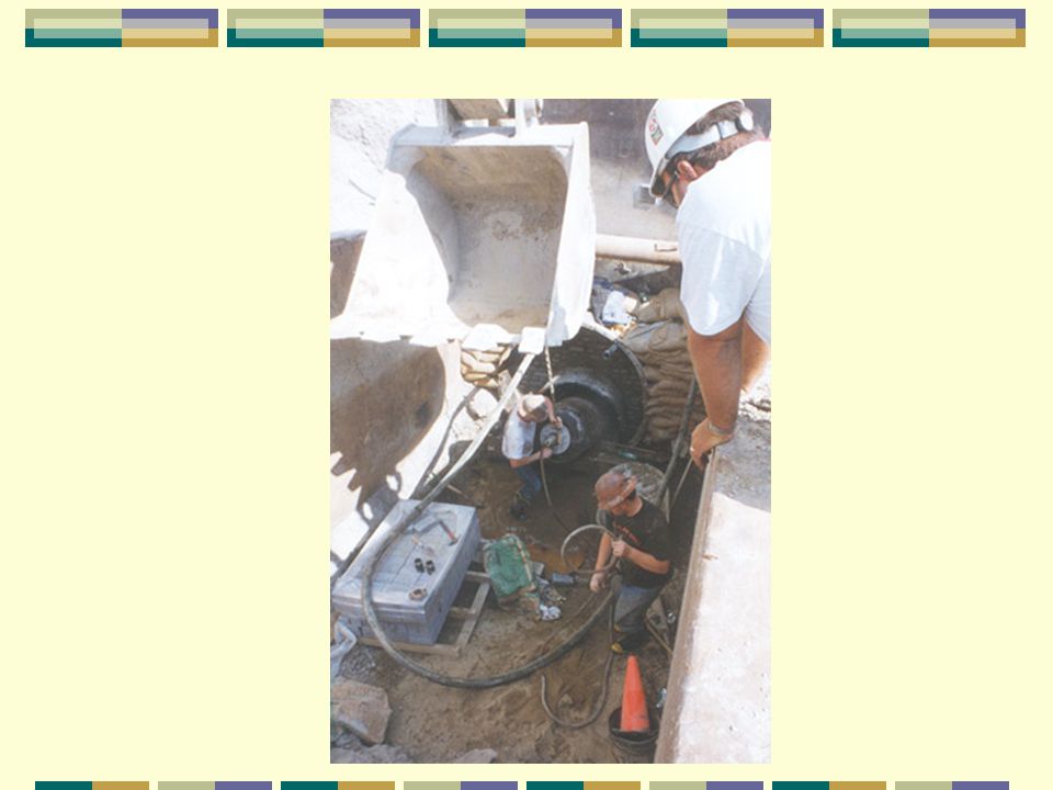
Exposure to Falling Loads
Employees must be protected from loads or objects falling from lifting or digging equipment. Procedures include: Employees are not permitted to work under raised loads. Employees are required to stand away from equipment that is being loaded or unloaded. Equipment operators or truck drivers may stay in their equipment during loading and unloading if the equipment is properly equipped with a cab shield or adequate canopy.

30
Exposure to Vehicles Procedures to protect employees from being injured or killed by vehicle traffic include: Providing employees with and requiring them to wear warning vests or other suitable garments marked with or made of reflective or high-visibility materials. Requiring a designated, trained flag-person along with signs, signals, and barricades when necessary.

31
Mobile Systems Warning
The following steps should be taken to prevent vehicles from accidentally falling into the trench: Barricades must be installed where necessary. Hand or mechanical signals must be used as required. Stop logs must be installed if there is a danger of vehicles falling into the trench. Soil should be graded away from the excavation; this will assist in vehicle control and channeling of run-off water.

32
Hazardous Atmospheres & Confined Spaces (1)
Employees shall not be permitted to work in hazardous and/or toxic atmospheres. Such atmospheres include those with: Less than 19.5% or more than 23.5% oxygen; A combustible gas concentration greater than 20% of the lower flammable limit; and Concentrations of hazardous substances that exceed those specified in the Threshold Limit Values for Airborne Contaminants established by the ACGIH (American Conference of Governmental Industrial Hygienists).
.")
33
Hazardous Atmospheres & Confined Spaces (2)
All operations involving hazardous atmospheres must be conducted in accordance with OSHA requirements (Subpart D of 29 CFR 1926) for personal protective equipment and for lifesaving equipment (see Subpart E, 29 CFR 1926). Engineering controls (e.g., ventilation) and respiratory protection may be required.
 for personal protective equipment and for lifesaving equipment (see Subpart E, 29 CFR 1926). Engineering controls (e.g., ventilation) and respiratory protection may be required.")
34
Hazardous Atmospheres & Confined Spaces (3)
When testing for atmospheric contaminants, the following should be considered: Testing should be conducted before employees enter the trench and should be done regularly to ensure that the trench remains safe. The frequency of testing should be increased if equipment is operating in the trench. Testing frequency should also be increased if welding, cutting, or burning is done in the trench.

35
Hazardous Atmospheres & Confined Spaces (4)
Employees required to wear respiratory protection must be trained, fit-tested, and enrolled in a respiratory protection program. Some trenches qualify as confined spaces. When this occurs, compliance with the Confined Space Standard is also required.

36
Emergency Rescue Emergency rescue equipment is required when a hazardous atmosphere exists or can reasonably be expected to exist. Requirements include: Respirators must be of the type suitable for the exposure. Employees must be trained in their use and a respirator program must be instituted. Attended (at all times) lifelines must be provided when employees enter bell-bottom pier holes, deep confined spaces, or other similar hazards. Employees who enter confined spaces must be trained.
 lifelines must be provided when employees enter bell-bottom pier holes, deep confined spaces, or other similar hazards. Employees who enter confined spaces must be trained.")
37
Water Accumulation (1) Methods for controlling standing water and water accumulation must be provided and should consist of the following if employees are permitted to work in the excavation: Use of special support or shield systems approved by a registered professional engineer. Water removal equipment used and monitored by a competent person.

38
Water Accumulation (2) Methods for controlling standing water and water accumulation must be provided and should consist of the following if employees are permitted to work in the excavation: Safety harnesses and lifelines used in conformance with 29 CFR Surface water diverted away from the trench.

39
Water Accumulation (3) Methods for controlling standing water and water accumulation must be provided and should consist of the following if employees are permitted to work in the excavation: Employees removed from the trench during rainstorms. Trenches carefully inspected by a competent person after each rain and before employees are permitted to re-enter the trench.

40
Daily Inspections (1) Inspections shall be made by a competent person and should be documented. The following guide specifies the frequency and conditions requiring inspections: Daily and before the start of each shift; As dictated by the work being done in the trench; After every rainstorm;

41
Daily Inspections (2) The following guide specifies the frequency and conditions requiring inspections: After other events that could increase hazards, e.g. snowstorm, windstorm, thaw, earthquake, etc.; When fissures, tension cracks, sloughing, undercutting, water seepage, bulging at the bottom, or other similar conditions occur;

42
Daily Inspections (3) The following guide specifies the frequency and conditions requiring inspections: When there is a change in the size, location, or placement of the spoil pile; and When there is any indication of change or movement in adjacent structures.

43
Soil Mechanics

44
Unit Weight of Soil Unit Weight Of Soil refers to the weight of one unit of a particular soil. The weight of soil varies with type and moisture content. One cubic foot of soil can weigh from 110 pounds to 140 pounds or more, and one cubic meter (35.3 cubic feet) of soil can weigh more than 3,000 pounds.
 of soil can weigh more than 3,000 pounds.")
46
Soil Mechanics A number of stresses and deformations can occur in an open cut or trench. For example, increases or decreases in moisture content can adversely affect the stability of a trench or excavation. The following diagrams show some of the more frequently identified causes of trench failure.

47
Boiling BOILING is evidenced by an upward water flow into the bottom of the cut. A high water table is one of the causes of boiling. Boiling produces a "quick" condition in the bottom of the cut, and can occur even when shoring or trench boxes are used.

48
Heaving or Squeezing Bottom heaving or squeezing is caused by the downward pressure created by the weight of adjoining soil. This pressure causes a bulge in the bottom of the cut, as illustrated in the drawing above. Heaving and squeezing can occur even when shoring or shielding has been properly installed.

49
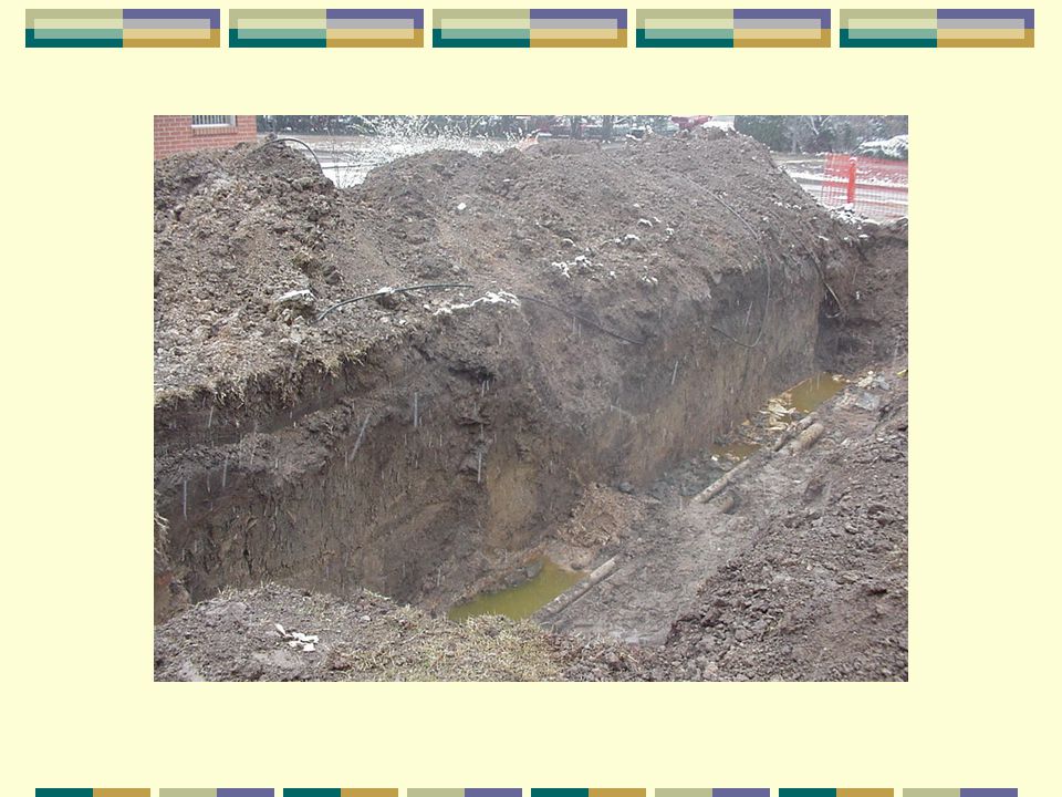
Subsidence and Bulging
An unsupported excavation can create an unbalanced stress in the soil, which, in turn, causes subsidence at the surface and bulging of the vertical face of the trench. If uncorrected, this condition can cause face failure and entrapment of workers in the trench.

50
Tension Cracks Tension cracks usually form at a horizontal distance of 0.5 to 0.75 times the depth of the trench, measured from the top of the vertical face of the trench.

51
Toppling In addition to sliding, tension cracks can cause toppling.
Toppling occurs when the trench's vertical face shears along the tension crack line and topples into the excavation.

52
Sloughing SLIDING or sloughing may occur as a result of tension cracks, as illustrated below.

53
Temporary Spoil Temporary spoil must be placed no closer than 2 feet from the surface edge of the excavation, measured from the nearest base of the spoil to the cut. This distance should not be measured from the crown of the spoil deposit. This distance requirement ensures that loose rock or soil from the temporary spoil will not fall on employees in the trench.

54
Temporary Spoil Spoil should be placed so that it channels rainwater and other run-off water away from the excavation. Spoil should be placed so that it cannot accidentally run, slide, or fall back into the excavation.

55
Temporary Spoil

56
Permanent Spoil Permanent spoil should be placed at some distance from the excavation. Permanent spoil is often created where underpasses are built or utilities are buried.

57
Soil Types

58
Soil Types OSHA categorizes soil and rock deposits into four types, A through D, as follows: Stable Rock Type A Soil Type B Soil Type C Soil Layered Soils

59
Stable Rock Stable Rock is natural solid mineral matter that can be excavated with vertical sides and remain intact while exposed. It is usually identified by a rock name such as granite or sandstone. Determining whether a deposit is of this type may be difficult unless it is known whether cracks exist and whether or not the cracks run into or away from the excavation.

60
Type A Soil Type A Soils are cohesive soils with an unconfined compressive strength of 1.5 tons per square foot (tsf) (144 kPa) or greater. Examples are often: clay, silty clay, sandy clay, clay loam and, in some cases, silty clay loam and sandy clay loam.

61
Type A Soil No soil is Type A if it: is fissured,
is subject to vibration of any type, has previously been disturbed, is part of a sloped, layered system where the layers dip into the excavation on a slope of 4 horizontal to 1 vertical (4H:1V) or greater, or has seeping water.
 or greater, or. has seeping water.")
62
Type B Soil Type B Soils are cohesive soils with an unconfined compressive strength greater than 0.5 tsf (48 kPa) but less than 1.5 tsf (144 kPa). Examples of soils are: angular gravel; silt; silt loam; previously disturbed soils unless otherwise classified as Type C;

63
Type B Soil Type B Soils meet the unconfined compressive strength or cementation requirements of Type A soils but are: fissured or subject to vibration; dry, unstable rock; or layered systems sloping into the trench at a slope less than 4H:1V (only if the material would be classified as a Type B soil).
.")
64
Type C Soil Type C Soils are cohesive soils with an unconfined compressive strength of 0.5 tsf (48 kPa) or less. Type C soils include granular soils such as gravel, sand and loamy sand, submerged soil, soil from which water is freely seeping, and submerged rock that is not stable.

65
Type C Soil Also included in this classification is material in a sloped, layered system where the layers dip into the excavation or have a slope of four horizontal to one vertical (4H:1V) or greater.
 or greater.")
66
Soil Classification

67
Soil Classification The visual and manual analyses, such as those noted as being acceptable in the regulations, shall be designed and conducted to provide sufficient quantitative and qualitative information as may be necessary to identify properly the properties, factors, and conditions affecting the classification of the deposits.

68
Soil Classification Each soil and rock deposit shall be classified by a competent person as Stable Rock, Type A, Type B, or Type C. The classification of the deposits shall be made based on the results of at least one visual and at least one manual analysis.

69
Layered Systems Layered systems. In a layered system, the system shall be classified in accordance with its weakest layer. Each layer may be classified individually where a more stable layer lies under a less stable layer.

70
Reclassification of Soil
If, after classifying a deposit, the properties, factors, or conditions affecting its classification change in any way, the changes shall be evaluated by a competent person. The deposit shall be reclassified as necessary to reflect the changed circumstances

71
Visual Evaluation

72
Visual Evaluation A visual test is a qualitative evaluation of conditions around the site. The entire excavation site is observed, including the soil adjacent to the site and the soil being excavated. If the soil remains in clumps, it is cohesive; if it appears to be coarse-grained sand or gravel that does not clump, it is considered granular. The evaluator also checks for any signs of vibration.

73
Visual Evaluation During a visual test, the evaluator should check for: crack-line openings along the failure zone that would indicate tension cracks, look for existing utilities or or other underground structures that indicate that the soil has previously been disturbed, and observe the open side of the excavation for indications of layers and the slope of those layers.

74
Visual Evaluation The evaluator should also look for signs of bulging, boiling, or sloughing (spalling), as well as for signs of surface water seeping from the sides of the excavation or from the water table. If there is standing water in the cut, the evaluator should check for "quick" conditions.
, as well as for signs of surface water seeping from the sides of the excavation or from the water table. If there is standing water in the cut, the evaluator should check for quick conditions.")
75
Visual Evaluation The evaluator should check for surcharging and the spoil distance from the edge of the excavation. Sources of vibration should also be noted that may affect the stability of the excavation face.

76
Manual Evaluation

77
Soil Test Equipment Pocket Penetrometers are direct-reading, spring-operated instruments used to determine the unconfined compressive strength of saturated cohesive soils. Once pushed into the soil, an indicator sleeve displays the reading. The instrument is calibrated in either tons per square foot (tsf) or kilograms per square centimeter (kPa). Penetrometers have error rates in the range of ± 20-40%.
 or kilograms per square centimeter (kPa). Penetrometers have error rates in the range of ± 20-40%.")
78
Soil Test Equipment Shearvane (Torvane). To determine the unconfined compressive strength of the soil with a shearvane, the blades of the vane are pressed into a level section of undisturbed soil, and the torsion knob is slowly turned until soil failure occurs. The direct instrument reading must be multiplied by 2 to provide results in tons per square foot (tsf) or kilograms per square centimeter (kPa).
. To determine the unconfined compressive strength of the soil with a shearvane, the blades of the vane are pressed into a level section of undisturbed soil, and the torsion knob is slowly turned until soil failure occurs. The direct instrument reading must be multiplied by 2 to provide results in tons per square foot (tsf) or kilograms per square centimeter (kPa).")
79
Thumb Penetration Soil Test
The thumb penetration procedure involves an attempt to press the thumb firmly into the soil in question. If the thumb makes an indentation in the soil only with great difficulty, the soil is probably Type A.

80
Thumb Penetration Soil Test
If the thumb penetrates no further than the length of the thumb nail, it is probably Type B soil.

81
Thumb Penetration Soil Test
If the thumb penetrates the full length of the thumb, it is Type C soil. The thumb test is subjective and is therefore the least accurate of the three methods.

82
Dry Strength Soil Test Dry soil that crumbles freely or with moderate pressure into individual grains is granular. Dry soil that falls into clumps that subsequently break into smaller clumps (and the smaller clumps can be broken only with difficulty) is probably clay in combination with gravel, sand, or silt.
 is probably clay in combination with gravel, sand, or silt.")
83
Dry Strength Soil Test If the soil breaks into clumps that do not break into smaller clumps (and the soil can be broken only with difficulty), the soil is considered unfissured, unless there is visual indication of fissuring.
, the soil is considered unfissured, unless there is visual indication of fissuring.")
84
Wet Thread Soil Test This test is conducted by molding a moist sample of the soil into a ball and attempting to roll it into a thin thread approximately 1/8 inch in diameter (thick) by 2 inches in length. The soil sample is held by one end. If the sample does not break or tear, the soil is considered cohesive.
 by 2 inches in length. The soil sample is held by one end. If the sample does not break or tear, the soil is considered cohesive.")
85
Drying Test Dry a sample that is approximately 1 inch thick by 6 inches in diameter until thoroughly dry. If it cracks as it dries, significant fissures are possible.

86
Drying Test Samples that dry without cracking are broken by hand.
If it breaks with difficulty, it is unfissured cohesive material. It it breaks easily by hand, it is either fissured cohesive material or granular.

87
Drying Test To distinguish between the two, pulverize the dried clumps by hand or by stepping on them. If the clumps do not pulverize easily, the material is cohesive with fissures. If the clumps pulverize into very small fragments the material is granular.

88
Protective Systems

89
Protective Systems Shoring Shielding Sloping Benching

90
Shoring Shoring is the provision of a support system for trench faces used to prevent movement of soil, underground utilities, roadways, and foundations.

91
Shoring Shoring (or shielding) is used when the location or depth of the cut makes sloping back to the maximum allowable slope impractical.
 is used when the location or depth of the cut makes sloping back to the maximum allowable slope impractical.")
92
Shoring Types Shoring systems consist of posts, wales, struts, and sheeting. Three basic types of shoring are: Timber Hydraulic Pneumatic

93
Timber Shoring

94
Hydraulic Shoring The trend today is toward the use of hydraulic shoring, a prefabricated strut and/or wale system manufactured of aluminum or steel. Hydraulic shoring provides a critical safety advantage over timber shoring because workers do not have to enter the trench to install or remove hydraulic shoring.

95
Hydraulic Shoring Other advantages of most hydraulic systems are that they: Are light enough to be installed by one worker; Are gauge-regulated to ensure even distribution of pressure along the trench line; Can have their trench faces "preloaded" to use the soil's natural cohesion to prevent movement; and Can be adapted easily to various trench depths and widths.

96
Hydraulic Shoring All shoring should be installed from the top down and removed from the bottom up. Hydraulic shoring should be checked at least once per shift for leaking hoses and/or cylinders, broken connections, cracked nipples, bent bases, and any other damaged or defective parts.

97
Typical Aluminum Shoring

99
Typical Aluminum Shoring

100
Typical Aluminum Shoring

102
Typical Aluminum Shoring

104
Pneumatic Shoring Pneumatic Shoring is similar to hydraulic shoring.
The primary difference is that pneumatic shoring uses air pressure in place of hydraulic pressure. A disadvantage to the use of pneumatic shoring is that an air compressor must be on site.

105
Pneumatic and Hydraulic Jacks

106
Hydraulic System

107
Screw Jacks Screw Jack Systems differ from hydraulic and pneumatic systems in that the struts of a screw jack system must be adjusted manually. This creates a hazard because the worker is required to be in the trench in order to adjust the strut. In addition, uniform "preloading" cannot be achieved with screw jacks, and their weight creates handling difficulties.

108
Screw Jack

109
Screw Jack System

112
Underpinning Underpinning involves stabilizing adjacent structures, foundations, and other intrusions that may have an impact on the excavation. As the term indicates, underpinning is a procedure in which the foundation is physically reinforced. Underpinning should be conducted only under the direction and with the approval of a registered professional engineer.

113
Shielding

114
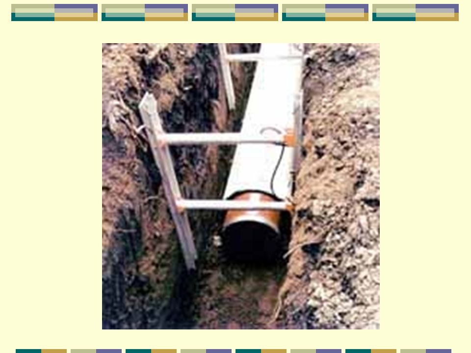
Trench Boxes Trench Boxes are different from shoring.
Instead of shoring up or otherwise supporting the trench face, they are intended primarily to shield workers from cave-ins and similar incidents.

115
Trench Boxes The excavated area between the outside of the trench box and the face of the trench should be as small as possible. The space between the trench boxes and the excavation side are backfilled to prevent lateral movement of the box. Shields may not be subjected to loads exceeding those which the system was designed to withstand.

116
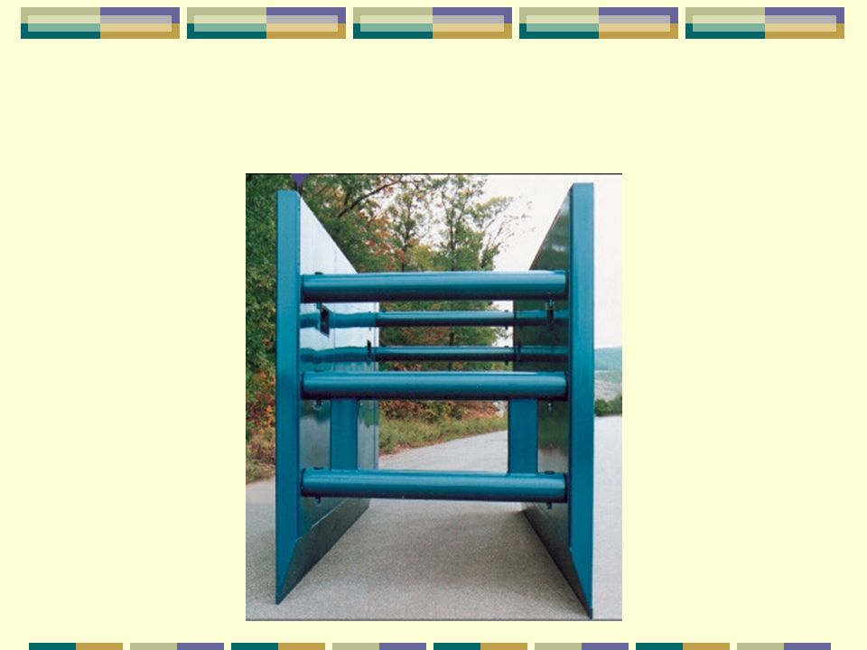
Trench Shield

118
Trench Shield, Stacked

122
Sloping

123
Allowable Slopes Soil Type Height/Depth Ratio Slope Angle Stable Rock
Vertical 90º Type A ¾:1 53º Type B 1:1 45º Type C 1 ½:1 34º (short-term)* ½:1 63º *For a maximum excavation depth of 12 feet for less than 24 hours
* ½:1. 63º. *For a maximum excavation depth of 12 feet for less than 24 hours.")
124
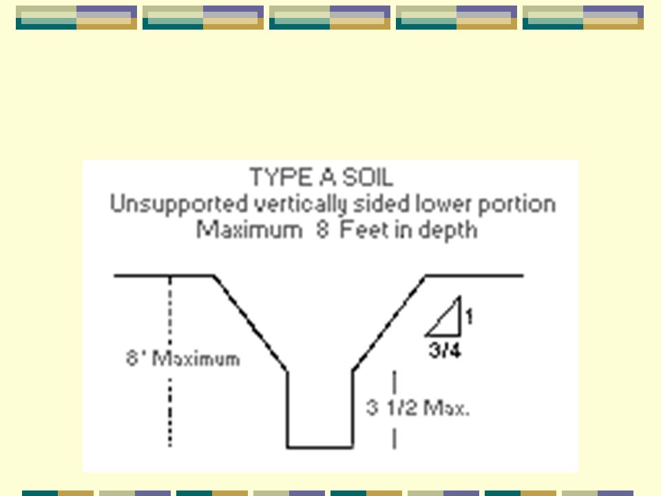
Type A Soil

125
Type A Soil Short Term

126
Type B Soil

127
Type C Soil

128
Type B Over Type A Soil

129
Type A Over Type B Soil

130
Type A Over Type C Soil

131
Type C Over Type A Soil

132
Type C Over Type B Soil

133
Type B Over Type C Soil

134
Sloping & Shielding

135
Slope & Shield Trench boxes are generally used in open areas, but they also may be used in combination with sloping and benching. The box should extend at least 18 inches above the surrounding area if there is sloping toward excavation. This can be accomplished by providing a benched area adjacent to the box.

136
Slope & Shield Earth excavation to a depth of 2 feet below the shield is permitted, but only if the shield is designed to resist the forces calculated for the full depth of the trench and there are no indications while the trench is open of possible loss of soil from behind or below the bottom of the support system.

137
Slope & Shield Conditions of this type require observation on the effects of bulging, heaving, and boiling as well as surcharging, vibration, adjacent structures, etc., on excavating below the bottom of a shield. Careful visual inspection of the conditions mentioned above is the primary and most prudent approach to hazard identification and control.

138
Slope & Shield

139
Slope and Shield

140
Slope and Shield

141
Benching There are two basic types of benching, simple and multiple.
The type of soil determines the horizontal to vertical ratio of the benched side.

142
Benching As a general rule, the bottom vertical height of the trench must not exceed 4 feet for the first bench. Subsequent benches may be up to a maximum of 5 feet vertical in Type A soil and 4 feet in Type B soil to a total trench depth of 20 feet.

143
Benching All subsequent benches must be below the maximum allowable slope for that soil type. For Type B soil the trench excavation is permitted in cohesive soil only.

144
B Soil Single Bench

145
B Soil Multiple Bench

146
Slope and Bench Maximum allowable slopes for excavations less than 20 feet based on soil type and angle to the horizontal are as follows:

Similar presentations