Download presentation
Presentation is loading. Please wait.

1
Is it Live or is it Memorex? Steve Voorhees KPFF Consulting Engineers

2
Who am I Steve Voorhees steve.voorhees@kpff.com Revit 2.0 130+ Revit Projects I am not an Engineer I used to be an ATC I started in this line of work designing Garbage Dumpsters Then Contracted to Intel Then KPFF for the past 17 years For those on the Green side out there I am a organic practices farmer too.

3
Objectives: Where we came from (3) types of detailing we use and how What else benefits from detailing this way? Typical details How to properly place the top of footing

4
Where we came from: Our Engineers meet with our clients to start relaying ideas and details as you all do via sketches on anything available:

5
Hey can you CAD this up? Then there was ACAD So excited no more group erasing! No more applying “Sticky Backs”! Block Libraries LSP Routines Palettes XREFS

6
Then…just when you thought it was safe to go back in the water… We’re going to need a bigger boat!

7
Revit is introduced! Now this is a cool idea… Lets concentrate on learning how to model: Plans, elevations and building sections Let’s not worry about details in Revit just yet: Keep details in ACAD or Link them in This was a HUGE mistake…

8
So what did we do? We learned how to do 2D details in Revit because, believe me linking them in just does not work well! DDV’ing (Import CAD Formats) in ACAD details then modifying them This method had issues of its own to deal with: Curved leaders and arrow head sizes Compressed fractions and Mtext
 in ACAD details then modifying them This method had issues of its own to deal with: Curved leaders and arrow head sizes Compressed fractions and Mtext.")
10
So what did work? We found (3) basic ways of creating details in Revit: 1.Draw it with detail components and detail lines 2.Live cut and freeze, then edit 3.Live cut the details; use line work, detail components and view filters
 basic ways of creating details in Revit: 1.Draw it with detail components and detail lines 2.Live cut and freeze, then edit 3.Live cut the details; use line work, detail components and view filters.")
11
First things first: We required a sheet to put the details on and a way to align the text: Using the Architectural title block, we started out using lines to create grids and setting instance or family parameters to these grid lines –Left on, showing up in plots –Save to Central if type –Snapping to invisible lines if used –Frustration

12
A better way to create your detail guide is: By editing the original title block: –Save as a new name We just add the word “Detail” to the name We clean all the title block information out except the sheet number

13
Create your detail grid and load it into your project

14
Ready to Draw Details We’re all set…now let’s figure out which option to use:

15
1.Draw it with detail components and detail lines: This is the way most beginners go at it. Those coming from ACAD are most comfortable this way: This method is perfect for the Napkin/Engineer sketch that is handed to you that needs to get in the set Using the tools under the Annotate Ribbon and the Detail Bar, You can manually draw lines for anything, but it can be quite time consuming

16
Use detail components for basic shapes Use Palette Legend for quick selection of shapes Create your coped connection members

17
Hidden lines show easy From the View Ribbon under Graphics just choose Show Hidden Lines. Pick your “Hiding” member and then the item you want to show hidden

18
2. Live cut and freeze, then edit This is used for the quick and dirty start to a detail: The Engineer goes around the model or plan views putting in section cuts and dropping them on a sheet The sheet is plotted and marked up. This now goes to drafting

19
Open the drafting view and double check your scales and the way it all looks Have your Extensions loaded (available to all subscription customers for free) Choose the Extensions Ribbon then Tools then Freeze Drawings
 Choose the Extensions Ribbon then Tools then Freeze Drawings")
20
Make your choice here:

21
The frozen view can be found as it said in the Drafting Views in your project browser. We leave the default line settings from Revit/AIA standard to create them

22
Now we have to explode the frozen view Pick your objects and the context menu automatically gives you the option for explode. Do a Full Explode this will completely disassemble it giving you lines and filled regions Now you can change them over to your standards very quickly, using Temporary Hide commands and pick up any markups for this view/detail

23
When completed we name the view based on the sheet and detail spot it is going into –Just some simple book keeping we do

24
Renaming the view is very simple - just go to your view properties box, scroll down to View Name and name it –If you name it: Sheet then Number it will be easy to find when you use a reference cut

25
Drag the view onto your sheet Before you drag the view onto the sheet, switch your title block to the Detail Guide Title block. Drag the view into the correct detail spot Activate your view, annotate and clean up all you want Use your text guide lines to make sure the text is all lined up

26
Once completed with annotation and detailing you can turn your Detail Guide Title block back to the Project Title block and you’re good to go!

27
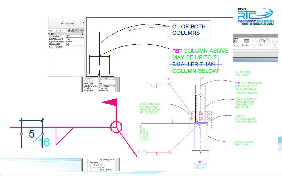
3. Live cut details Live cuts can be great for “A-Typical” detail situations The problem occurs when things move and you know they are going to move Here are some simple guidelines and rules to follow when cutting live detail cuts:

28
Cut and set your view prior to doing any work –Depth –Size of view box Once the view is set, Pin the view

29
Now that the view is set let’s turn on the Architect’s model and set our Visibility/Graphics Overrides for the section

30
After seeing what you have, go back into VG (Visibility Graphics) and lets set the RVT Link display to Custom and then under the Annotation Categories tab set it to Custom and turn everything off
 and lets set the RVT Link display to Custom and then under the Annotation Categories tab set it to Custom and turn everything off")
31
Rename the view to sheet - #, then drag this view onto a sheet so you can start detailing it Drop in the components you want and place them where they need to be You can use components or detail lines - Do not use modeling lines –They will show throughout the model Once your items you want are in, you can then turn off the model elements you do not want to see via Visibility Graphics

32
When setting your Visibility Graphics you want to make sure you leave your Detail Items and your Lines checked to On. All others can be turned off

33
Annotation Categories are dependent on the situation. If you need grids or levels turn them on, if not they can be turned off Now you’re ready to start annotating

34
Let’s cut it on plan We don’t want it to move or change We don’t want the cut to be deleted We want to cut it in multiple places

35
Pin that Cut!!! –Prevents accidental moves Set Hide at scales coarser than: –12” = 1’-0” or 1-1 –Hides the Parent Cut –Prevents from moving –Hides in more than one place

36
Now you’re ready to “Ref. Cut” Revit 101 –Section –Reference other view –Scroll down find your detail –Cut it

37
Why use detail components on live cuts? –If it changes, you can turn it on and see the change –Easy to verify the detail works –When you make changes to the model it will have to be redone most of the time if it changes –Saves time and everyone knows that…

38
Other times to use Live Cuts Elevations and Sections Cladding backing Stairs

39
Elevations and Sections Always wanting to show accurate Modeled correctly Use detail components, detail lines and filled regions, surface patterns, painting

40
Cladding Backing Don’t lose money here! Use Arch ½ toned and add detail lines

41
Stairs The fastest and easiest way to detail stairs in a project we have found is…

42
Stairs Live cut your stairs so you can use Elevation Indicators at landings and you can cut live or drafting view details from it

43
Let’s talk typical details aka: can details We all have them –I hope We don’t want to steal from project to project –What happens if we forget to update some old information? In AutoCAD we had a detail library, tool palettes and ribbons –Not in Revit

44
Create a blank RTD model RTD (Revit Typical Details) The only thing in this model is going to be drafting views of typical details
 The only thing in this model is going to be drafting views of typical details")
45
Name your drafting views the same way you have them in your library so they are easy to locate Make sure to fill in the Title on the Sheet –This allows for it to come in pre-named

46
Create an RTD for each discipline you work with that you have typical details for: Helpful hint –Create them in the oldest version you have projects created in

47
Bring in those typical details From the Insert tab –Insert From File –Insert Views from File From the Insert Views dialog box choose the details you want

48
Once the views are in you can: –Rename them to fit your standards for drafting view naming –Drag them on the sheets and adjust them to meet your needs

49
Let’s talk footings Revit tags Bottom of footing –This is our way of calling it out This tells the excavator how far to dig (no need for them to have to figure it out) –There are some companies out there that call out the Top of footing The excavator will have to calculate in the thickness of footing before digging Today we will talk about Isolated Footings and Continuous Footings including steps
 –There are some companies out there that call out the Top of footing The excavator will have to calculate in the thickness of footing before digging Today we will talk about Isolated Footings and Continuous Footings including steps")
50
Footing Depth Controlled by column depth Can be changed manually Depth is determined from site drawings linked in and/or from geotechnical reports

51
With columns in and bottom depth set, we can place our footings and tag them –Recommend using the Type Mark Tag for this –Set the name of your footing with the same designator as in your footing schedule –Book keeping is very important!

52
If you have a flat site and a slab you can speed up the process by creating a level for the top of footing –Set your columns to this level –Set this level to a Work set that can be filtered –Bottom of footing tags work just fine

53
If you have to call out top of footing EL. (Elevation) –Use a spot elevation You can set brackets if needed in the settings If not, just use plain and create your tag
 –Use a spot elevation You can set brackets if needed in the settings If not, just use plain and create your tag.")
54
Continuous Footings Types –Retaining –Bearing

55
Retaining Footings Depths are determined the same way as other footings Size of footing is engineered by an Engineer Placed on a wall using Toe Length and Heel Length (Heel being the long side buried) Don’t forget the wall thickness
 Don’t forget the wall thickness")
56
If you put it in on the wrong side you can Flip it, don’t redraw it!

57
Bearing Footings Depths are determined the same way as other footings Size of footing is engineered by an Engineer Tagged as a normal footing

58
Stepped Footings Created multiple ways –Splitting the wall –In place component –Wedge

59
Stepped Footings Use your Spot Elevation to tag Updates when changed Does not mess up normal tag

60
Recap Where we came from (3) types of detailing we use and how What else benefits from detailing this way Typical details Footings
 types of detailing we use and how What else benefits from detailing this way Typical details Footings")
61
Questions? Steve Voorhees KPFF Consulting Engineers

Similar presentations